SKETCH-BASED
SKELETON-DRIVEN 2D ANIMATION AND
MOTION CAPTURE
JUNJUN PAN
June 2009
National Centre for Computer Animation
Media School
i
This copy of the thesis has been supplied on condition that anyone who consults it is understood to recognise that its copyright rests with its author and due acknowledgement must always be made of the use of any material contained in, or derived from, this thesis.
ii
SKETCH-BASED SKELETON-DRIVEN 2D
ANIMATION AND MOTION CAPTURE
JUNJUN PAN
A thesis submitted inpartial fulfilment of the requirements of the Media School of Bournemouth University for the degree of Doctor of Philosophy
June 2009
National Centre for Computer Animation
Media School
iii
Copyright © 2009 JUNJUN PAN All rights reserved
iv
ABSTRACT
This research is concerned with the development of a set of novel sketch-based skeleton-driven 2D animation techniques, which allow the user to produce realistic 2D character animation efficiently. The technique consists of three parts: sketch-based skeleton-driven 2D animation production, 2D motion capture and a cartoon animation filter.
For 2D animation production, the traditional way is drawing the key-frames by experienced animators manually. It is a laborious and time-consuming process. With the proposed techniques, the user only inputs one image of a character and sketches a skeleton for each subsequent key-frame. The system then deforms the character according to the sketches and produces animation automatically. To perform 2D shape deformation, a variable-length needle model is developed, which divides the deformation into two stages: skeleton driven deformation and nonlinear deformation in joint areas. This approach preserves the local geometric features and global area during animation. Compared with existing 2D shape deformation algorithms, it reduces the computation complexity while still yielding plausible deformation results.
To capture the motion of a character from exiting 2D image sequences, a 2D motion capture technique is presented. Since this technique is skeleton-driven, the motion of a 2D character is captured by tracking the joint positions. Using both geometric and visual features, this problem can be solved by optimization, which prevents self-occlusion and feature disappearance. After tracking, the motion data are retargeted to a new character using the deformation algorithm proposed in the first part. This facilitates the reuse of the characteristics of motion contained in existing moving images, making the process of cartoon generation easy for artists and novices alike.
Subsequent to the 2D animation production and motion capture, a “Cartoon Animation Filter” is implemented and applied. Following the animation principles, this filter processes two types of cartoon input: a single frame of a cartoon character and motion capture data from an image sequence. It adds anticipation and follow-through to the motion with related squash and stretch effect.
v
ACKNOWLEDGMENT
First and foremost, I would like to thank my supervisors, Professor Jian J. Zhang, Dr. Xiaosong Yang and Dr Reza Sahandi. Professor Zhang and Dr. Xiaosong Yang have guided me to the wonderland of computer animations. They are both wonderful and kind people. It is joyful to discuss problems with them and the sparks of inspirations often come from such discussions. I shall never forget the abundant time and efforts Professor Zhang has put into my thesis and the directions from Dr. Xiaosong Yang in research. Dr Reza Sahandi has given me a lot of valuable comments on my thesis writing and helped me finalize the draft. I would not have finished the writing so quickly without their help.
I would like to thank Claudia Moore and her animation team for testing our prototype system and
providing us with helpful suggestions.My sincere appreciation goes to Mrs. Jan Lewis and Mr. Dan
Cox for their daily support and kind helps in non-academic matters.
My study and research here is financially supported by the bursary of Bournemouth University and the Overseas Research Students Award Scheme (ORSAS). I also would like to take this opportunity to acknowledge their support.
vi
LIST OF CONTENTS
Abstract iv
Acknowledgement v
List of Contents vi
List of Figures viii
List of Tables x
1. Introduction 1
1.1 Background 1
1.2 Research Objectives 3
1.3 Framework and Overview 3
1.4 Contributions 7
1.5 Thesis Structure 8
2. Related Work 10
2.1 Traditional Cartoon Production 10
2.2 Recent Progress in 2D Animation 13
2.3 2D Shape Deformation 15
2.4 2D Motion Capture and Retargeting 16
2.5 “The Cartoon Animation Filter” 18
2.6 Summary 19
3. Sketch-based Skeleton-driven 2D Animation 20
3.1 Overview 20
3.2 Silhouette Detection and Triangulation 21
3.3 Skeletonization and Decomposition 24
3.4 2D Shape Deformation 27
3.4.1 The Variable-Length Needle Model 27
3.4.2 Stage One: Skeleton Driven Deformation 28
3.4.3 Stage Two: Nonlinear Deformation in Joint Areas 30
3.5 Depth Adjustment and Fine Tuning 34
3.6 In-betweens 37
3.7 Experiments and Comparison 38
3.8 Summary 41
4. Motion Capture for 2D Character Animation 43
vii
4.2 Preconditions 44
4.3 Initialization 44
4.4 Tracking 46
4.4.1 Visual Feature: Template Matching 46
4.4.2 Geometric Feature: Position Prediction 49
4.4.3 Mixed Optimization 52
4.5 Retargeting 54
4.6 Experiments 55
4.7 Summary 65
5. Implementation and Application of “Cartoon Animation Filter” 67
5.1 Working Principle 67
5.2 Implementation and Application 69
5.2.1 Filtering Single Frame of Cartoon Character 70
5.2.2 Filtering Motion Capture Data 72
5.3 Summary 74
6. System Interface and Evaluation 76
6.1 System Structure 76
6.2 Interface and Interaction 78
6.3 Auxiliary Functions 80
6.4 Evaluation and Discussion 82
6.4.1 Testing Procedures 83
6.4.2 Testing Result 83
6.4.3 Feedback 90
6.5 Summary 90
7. Conclusions and Future Work 92
7.1 Conclusions 92
7.2 Limitations and Future Work 94
Appendix A. Questionnaire 97
Appendix B. Some Sketches Provided by Animators 104
B.1 Sketches Provided by Animator 1 104
B.2 Sketches Provided by Animator 2 105
viii
LIST OF FIGURES
Figure 1.1 Structure of the thesis 9
Figure 2.1 Pipeline structure of two different systems in cartoon production 13 Figure 3.1 Experimental result of silhouette detection for a cartoon character 22 Figure 3.2 16 possible cases and direction of the moving 2 x 2 grid on the next
iteration
23 Figure 3.3 Process of our designed Constrained Delaunay Triangulation 23
Figure 3.4 3
×
3 region in a binary image 25Figure 3.5 Result of skeletonization and decomposition 26
Figure 3.6 Illustration of our definition for different types of vertices and triangles
27 Figure 3.7 Variable-length needles model for a cartoon character 28 Figure 3.8 Deformation with (middle) and without (right) global area
preservation
29
Figure 3.9 Deformation process 30
Figure 3.10 Depth adjustment 35
Figure 3.11 Sketch map of the fine tune process with sketch curve 36
Figure 3.12 Fine tuning local geometric detail 37
Figure 3.13 Generation of in-between frames 38
Figure 3.14 Comparing our algorithm with the approaches in [Igarashi et al. 2005] and [Weng et al. 2006]
38 Figure 3.15 Flower model deformed by our algorithm and [Weng et al. 2006] 39 Figure 3.16 Deformed results with different sampling density of cartoon
character
41
Figure 4.1 Initial setup for motion capture 45
Figure 4.2 Target character 46
Figure 4.3 Colour feature matching of joint regioncmtfrom frame t to frame t+1 48
Figure 4.4 Searching route in colour feature matching 48
Figure 4.5 Rotation of moving rectangles for a limb joints 49
Figure 4.6 The operation of the Kalman filter 51
Figure 4.7 Tracking and retargeting 54
Figure 4.8 Motion of a jumping cartoon man retargeted to a new character 59 Figure 4.9 Joint tracking of a running horse in a rendered 3D animation image
sequence and retargeting to a cartoon gazelle
65
Figure 5.1 The cartoon animation filter 68
Figure 5.2 Anticipation and follow-through effect after filtering 69
ix
Figure 5.4 Filtering a jumping cartoon man 72
Figure 5.5 Filtering motion capture data from image sequence 74
Figure 6.1 Pipeline structure of system 77
Figure 6.2 Interface of the prototype system 79
Figure 6.3 Decomposition correction 81
Figure 6.4 Six groups of cartoon characters deformed by our system 90
Figure B.1 Key-frames of the throwing 105
x
LIST OF TABLES
Chapter 1. Introduction _________________________________________________________________________________ 1
CHAPTER 1
INTRODUCTION
1.1 Background
Character modelling and animation involves everlasting efforts and extensive research over many decades since the advent of the first computerized human models in the 1970s [Isaac 2003]. At present, their applications have spread to a great variety of fields, including media, biomedicine, military, education and entertainment. Human-like virtual characters which congest in computer games (e.g. “Warcraft”) and films (e.g. “Avatar”, “King Kong”, “Shrek”, etc) are playing a remarkable role in modern public media and entertainment.
Generally, character modelling and animation are regarded as a challenging and labour-intensive work that requires both professional skills and artistic expertise. To build and animate a vivid virtual character, three stages are usually needed in this process: modelling, motion and deformation. These animation production steps require extensive expertise (mesh modelling, dynamics, kinematics, physical simulation, etc), professional software (Maya, 3DS MAX, etc), special equipments (3D laser scanner, motion capture system, etc) and proficient computer skills [Fox 2004]. Therefore, ordinary users are hardly given the opportunity to produce convincing animation due to lack of appropriate skills, knowledge and resources.
Chapter 1. Introduction _________________________________________________________________________________
2
In addition, for animators, animation production is a big systemic project which involves collaborations among various specialists and production teams [Fox 2004, Isaac 2003]. For example, a typical CG animation pipeline generally contains three stages: preproduction (scriptwriting, storyboarding, character design, etc), production (modelling, rigging, animation, scene layout, rendering, etc), and postproduction (compositing, video editing, etc). In the preproduction process, 2D artists in the creative team usually design character appearances and storyboards through freehand sketching. Next, these drawings and storyboards are implemented by 2D/3D modelers and animators in the production team through modelling, rigging, animation, and rendering. In the last stage, these semi-finished clips are sent to the technicians for the final video editing and compositing. Therefore, animation production is usually a big and time-consuming job, which is too complicated and overwhelming for a single artist or animator to undertake.
Sketch-based animation, as a useful tool for character modelling and animation, provides a good solution to animators and ordinary users to avoid the difficulties discussed above due to its intuitiveness and simplicity. Many papers [Davis et al. 2003, Thorne et al. 2004, Li 2006, Yuki et al. 2007] have been published and several techniques have been developed into commercial software, e.g. [Igarashi et al. 1999]. With the help of sketch-based techniques, animators can translate their 2D drawings into 3D models. Instead of handling the details step by step, the modeller/animator can visualize and evaluate the fast-prototyped models at an early stage, which can be further refined with other 3D tools to meet the artistic needs.
Nevertheless, compared with above progress in 3D animation, 2D animation (also can be called cartoon or cel animation) has not benefited as much from these achievement. Up until today, most professional cartoon studios still produce huge amounts of animation (key-frames and in-betweens) manually [Daniel 2006]. Largely overlooked by the computer graphics community, the 2D animation process remains laborious, time-consuming and predominately manual, in contrast with the contemporary 3D animation production process.
Chapter 1. Introduction _________________________________________________________________________________
3
1.2
Research Objectives
This research is aimed at investigating and designing an efficient and easy-to-use technique for quick articulated cartoon production. And a functional system is expected to be developed to cope with the practical requirements in 2D animation. The research objectives are in the following aspects:
Investigating and evaluating the traditional cartoon production process. Designing and developing a practical and easy-to-use sketch-based technique to generate cartoon animation.
Investigating the existing 2D deformation and animation techniques for cartoon character. Developing a new real-time 2D shape deformation algorithm to be used with the sketch-based cartoon strategy.
Designing and developing a useful motion capture and retargeting technique for 2D character animation.
Developing and implementing an animation system with sketching interface and auxiliary functions for cartoon production.
Implementing a “Cartoon Animation Filter” and applying it to the final cartoon output from the developed system.
1.3
Framework and Overview
The generation of key-frames and in-between frames are two of the most important and labour intensive steps in 2D animation production. For efficient use of the animators’ time, the key-frames are drawn by skilful key-framers, while the in-between frames are created by those who are less experienced and skilful, known as the in-betweeners. Although some software tools, e.g. Animo, Toon Boom [2008], have been helpful in generating in-between frames, they often lack ‘personality’ in comparison with those created by an animator. Often, the in-betweens generated by software have to be tweaked by the animator to add ‘personality’ to the animation. In practice, many in-betweens remain created manually. On the same point, if the animator were able to produce a key-frame more easily and efficiently, then he/she could produce more densely spaced key-frames resulting in a much smaller number
Chapter 1. Introduction _________________________________________________________________________________
4
of in-betweens need to be generated. Even if the in-betweens were generated by software, it is reasonable to argue that they are unlikely to need further tweaking, because the number of in-betweens is so small and would have little effect on the quality of animation. Our techniques presented in this thesis are based on this argument.
Motivated by the skeleton-driven 3D animation techniques, sketch-based animation techniques, and recent progress in 2D deformations, e.g. [Igarashi 2005], in this thesis a novel technique is presented with the aims to improve the degree of automation for the production of 2D animation without sacrificing the quality. Our technique consists of three parts, Part 1: 2D animation sequence generation by sketch, Part 2: motion capture and retargeting and Part 3: application of “cartoon animation filter”. Part 1 can be used independently to create an animation sequence. If it is combined with Part 2, one can easily reuse the ‘motion’ of an existing animation sequence and apply it to a different character. Part 3 is used to add exaggerated effects to the final result.
The most important issue concerned is how to handle the complex shape deformation of characters. In Part 1, for a character at a given orientation (for example, side view, front view or back view), the user first generate its skeleton by analyzing the geometry of the boundary curve. Similar to a 3D character, the skeleton acts as the driving structure and controls the deformation of the character. To deform a character, a variable-length needle model is introduced and an algorithm called skeleton driven + nonlinear least squares optimization is proposed. The idea is to divide the 2D shape deformation into two components. The first is skeleton driven deformation, which is controlled purely by the corresponding segment of the character skeleton; and the other is nonlinear least squares optimization, which is to compute the deformation in the joint areas which are associated with the skeletal joints. Our observation suggests most complex deformation occurs around the joint areas of a character during animation. For the interest of computational efficiency, the skeleton driven deformation is treated simply as a linear transformation. Only the deformation in the joint areas is solved by nonlinear least squares optimization. To
Chapter 1. Introduction _________________________________________________________________________________
5
ensure realistic deformation, properties such as boundary feature preservation, interior smoothness, the global area preservation are maximized during animation. The property of area preservation is also easily incorporated into the variable-length needle model. With our technique, once the first frame is given, the animator can easily create an animation sequence by drawing the skeleton for each subsequent key-frame. The system will produce the deformed character shape automatically, saving the animator from drawing the whole frame. Although the primary application of our technique is 2D animation production, it is also applicable to interactive graphical systems where the user can deform a 2D shape directly by moving /deforming its skeleton. Since it is very simple to use, it is anticipated that this approach is not only of interest to professional cartoon production studios, but also to novice 2D animators and artists for creating 2D moving graphics.
Motion capture and retargeting is another big issue in character animation. At present, most of the research work and academic papers in this field focuses on 3D animation. Although large amounts of video, cartoon and traditional 2D moving images exist, few effective approaches are available to make use of these abundant resources due to the special characteristics and principles of 2D animation [Williams 2001, Isaac 2003]. The main objective of Part 2 is to patch this obvious gap. Because our cartoon production technique is skeleton-based, the idea of Motion Capture from 3D animation is naturally borrowed to capture the ‘motion’ of a 2D animation sequence, and retarget the captured motion to a different character. However, instead of capturing the motion of a performer with a 3D motion capture device, the motion of a 2D character is captured from an image/cartoon/video sequence. Another obvious difference it has from the 3D case is that the skeleton length of a 3D performer is constant during animation, i.e. the skeleton segments are in essence rigid. To capture the motion of a performer, the 3D Motion Capture Officer embeds (fits) an animation skeleton into the 3D marker points during the calibration process, which helps the system compute the rotational angle of each skeletal segment relative to its parent (Autodesk Motion Builder [2008]). In 2D animation, changing length feature in the form of stretching and compression is one of the most powerful and expressive principles of animation [Williams 2001]. Fortunately, with our
Chapter 1. Introduction _________________________________________________________________________________
6
method, the 2D skeleton can be used to represent these important and expressive transformations.
Retargeting the captured motion to a different character has been extensively studied in 3D animation, e.g. [Gleicher 1998], and can be applied to 2D animation with our method. Here a feature region based tracking method is presented, commonly used in computer vision, to extract the motion of 2D objects in video or an image sequence. A mixed optimization coupled with template matching and Kalman prediction is applied. After the user has located all the joint regions of a character in the first frame, the system will track the motion of the joints automatically in the subsequent frames. The captured motion information is then retargeted to the predefined skeleton of a new 2D character to generate the deformation (animation). To avoid the problem of self-occlusion and feature disappearance during the tracking process, both visual and geometric features are taken into account.
In a sense, cartoon animation is the art of manipulating motion to emphasize the primary actions of character. Experienced animators can guide the viewers’ perceptions of the motion and literally bring it to life. Isaac Kerlow [Isaac 2003] introduced twelve principles of animation which were created in the early 1930s by animators in Walt Disney Studios. These principles were used to guide cartoon design and animation production as well to train the art students. These twelve principles became one of the foundations of hand-drawn cartoon character animation, which are mostly about five things: directing the performance, acting the performance, representing reality (through modelling, drawing, and rendering), interpreting real world physics, and editing a sequence of actions [Williams 2001]. Some original principles, such as anticipation and follow-through to the motion with related squash and stretch, are still useful today because they help us to create more “animated” characters and motions. In 2006, Jue Wang et al. [2006] present a technique named “Cartoon Animation Filter”. It is a simple filter that takes an arbitrary motion signal as input and modulates it in such a way that the output motion is more alive. The filter only needs the user to set the desired filtering strength as the parameters. It can cope with three different types of motion input
Chapter 1. Introduction _________________________________________________________________________________
7
including: hand drawn motion, video objects and 3D MoCap data. The superiority of this technique lies in its simplicity and generality, which provides a good reference for our work. So in the third part of our work, a modified “Cartoon Animation Filter” was implemented and applied to the cartoon output from the first or the second part.
1.4 Contributions
There are five key contributions in this thesis:
1. A sketch-based skeleton-driven 2D animation technique is presented. To produce new frames, the user only needs to input one image of the character and sketch skeletons for subsequent key-frames.
2. To handle 2D shape deformation, a variable-length needle model is developed and the skeleton driven + nonlinear least squares optimization algorithm is introduced. Compared with other approaches for a similar purpose, it is more efficient and able to produce plausible deformation results.
3. A novel skeleton-based 2D motion capture technique is presented. It can extract the motion from cartoon, video and rendered moving image sequences by tracking the motion of the skeleton joints. Using both geometric and visual features, it prevents self-occlusion and feature disappearance in moving images. 4. A modified “Cartoon Animation Filter” is implemented and applied to the two
types of cartoon output from the developed system. It can add exaggerated effect, such as squash and stretch, to the final result and make the animation more vivid. 5. A prototype animation system is developed to implement the described
techniques above. This system is tested and evaluated by several cartoon examples in experiments. Coupled with assistant functions, it can deal with the most practical requirements for character cartoon production.
During the period of the research, several related publications have produced to report the technical developments achieved, which are listed as follows:
Chapter 1. Introduction _________________________________________________________________________________
8
• Pan, J., Yang, X., Xie, X., Willis, P., and Zhang, J. Automatic Rigging for Animation Characters with 3D Silhouette. Computer Animation and Virtual Worlds, 20(2-3): 121-131, Jun. 2009.
• Pan, J., Zhang, J., Zhang, Y., and Zhou, H. X-ray-Based Craniofacial Visualization and Surgery Simulation. In book: Recent Advances in the 3D Physiological Human. Springer-Verlag (LNCS), August 2009, pp.208 -224. • Chang, J., Pan, J., and Zhang, J. Modeling Rod-like Flexible Biological
Tissues for Medical Training. In book: Modelling the Physiological Human. Springer-Verlag (LNCS), Jan 2010, pp.51-61.
• Wang, M., Chang, J., Pan, J., Jian J. Zhang. Image-based bas-relief generation with gradient operation. Proceedings of the 11th IASTED International Conference Computer Graphics and Imaging, February, 2010, Austria.
• Pan, J. and Zhang, J. Sketch-based skeleton-driven 2D animation and motion capture. (submitted to Visual Computer)
1.5 Thesis Structure
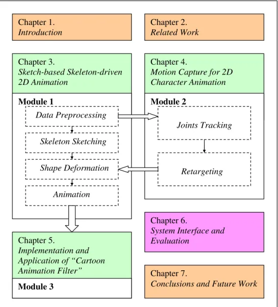
The structure of the thesis is outlined in Figure 1.1.
Chapter 1 is a brief introduction of this thesis. Chapter 2 reviews and evaluates the traditional cartoon production process first, and points out places for improvements. Then the existing techniques in 2D shape deformation and 2D motion capture are investigated. In the end, the “Cartoon Animation Filter” technique is discussed. Chapter 3 introduces the sketch-based skeleton-driven 2D animation technique. A variable-length needle model and the skeleton driven + nonlinear least squares optimization algorithm for 2D shape deformation are particularly described. Chapter 4 introduces the skeleton-based 2D motion capture and retargeting technique. The core content is a joint tracking algorithm based on computer vision. Chapter 5 describes the implementation of the “Cartoon Animation Filter” and its application in the final output exaggeration. Chapter 6 introduces the structure and interface of
Chapter 1. Introduction _________________________________________________________________________________
9
this prototype 2D animation system. The animation system is also tested and evaluated with several practical cartoon examples in experiments. Chapter 7 concludes the thesis and identifies potential directions in future research and development.
Figure 1.1 Structure of the thesis Chapter 1. Introduction Chapter 3. Sketch-based Skeleton-driven 2D Animation Chapter 2. Related Work Chapter 7.
Conclusions and Future Work
Module 1 Data Preprocessing Skeleton Sketching Shape Deformation Animation Chapter 4.
Motion Capture for 2D Character Animation
Module 2
Chapter 6.
System Interface and Evaluation Joints Tracking Retargeting Chapter 5. Implementation and Application of “Cartoon Animation Filter” Module 3
Chapter 2. Related Work _________________________________________________________________________________
10
CHAPTER 2
RELATED WORK
Research on “Sketch-based Skeleton-driven 2D Animation and Motion Capture” mainly involves two aspects: 2D animation generation and motion capture. There is a significant body of previous work concerned with these two research areas. First, the traditional cartoon production process is discussed. Then the most relevant developments are reviewed.
2.1 Traditional Cartoon Production
Traditional animation, which can also be called cel animation or hand-drawn animation, was first used for the animated films in the 20th century. The individual frame of a traditional animated film is photograph of drawings which firstly drawn by animators on a paper. To create the performance of movement, each drawing differs slightly from the previous one. The animators' drawings are traced or photocopied onto a transparent acetate sheet which is called cels. The cels are filled in with assigned colours or tones on the side opposite the line drawings. The completed character cels are photographed one by one into motion picture film in front of a painted background by a rostrum camera.
Chapter 2. Related Work _________________________________________________________________________________
11
The traditional cel animation production became obsolete at the beginning of the 21st century. Nowadays, animators' drawings and the backgrounds are scanned into or drawn online directly on a computer. Various computer graphics softwares (such as “Toon boom”, “Animo”) are used to colour the drawings and simulate camera movement and effects. The final animated image sequence is output to several types of media, including traditional film and newer media such as digital video. The visual feeling of traditional cel animation is still preserved, and the style of animators' work has remained essentially the same as before. Some animation production studios used the term "tradigital" to describe the cel animation which makes extensive use of the computer graphics technology.
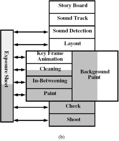
According to the survey by Robertson [1994] and Sykora [2006], there are two kinds of commercial computer graphics core systems: Ink and Paint and Automated In-Betweening are used to produce 2D animation in professional cartoon studios. The pipeline structure of these two systems is illustrated in Figure 2.1 (a) and (b) [Fekete et al. 1996]. The automatic work done by computers is marked with a dark background. In both of them, most steps have an exposure sheet, which lists all the frames in a scene. Each line includes the phoneme pronounced by characters and the position where the camera will shoot the cartoon figures. Each scene also has a set of stages, of which only the background can be painted in parallel with the animation stages. These stages include:
Story Board: Splits script into scenes with music and dialogue.
Sound Track: Records music and dialogue in prototype form.
Sound Detection: Fills the dialogue column of an exposure sheet.
Layout: Manages backgrounds and main character positions, with specifications for camera movement and other animation characteristics.
Background Painting: Paints the background according to the layout.
Key Frame Animation: Draws extreme positions of characters as specified by the layout, and provides instructions for the in-betweeners.
Chapter 2. Related Work _________________________________________________________________________________
12
In-Betweening: Draws the missing frames according to the key-frame animator’s instructions.
Cleaning: Cleans up the drawings to achieve final quality of the strokes.
Paint: Photocopies the clean drawings onto acetate celluloid (cels) and paints zones with color.
Check: Verifies animation and backgrounds according to the layout and approves for shooting.
Record: Shoots frame-by-frame on video or film, using a rostrum.
(a)
Chapter 2. Related Work _________________________________________________________________________________
13
(b)
Figure 2.1 Pipeline structure of two different systems in cartoon production [Fekete et al. 1996]. (a) Ink and Paint, (b) Automated In-Betweening
For both of Ink and Paint system and Automated In-Betweening system, all important artwork (key-fame animation) is still drawn manually, which usually needs 50~300 animators to draw thousands of characters in different poses with human hands, and later digitized and managed by the computer after the cleaning stage. Therefore, to significantly reduce the human labour input in the traditional cartoon making process, a novel sketch-based skeleton-driven cartoon technique is proposed in this thesis. In this technique, once a template image of a character is given, the animator can easily create an animation sequence by just drawing the skeleton for each subsequent key-frame. This saves the animator from drawing the whole frame.
2.2 Recent Progress in 2D Animation
Chapter 2. Related Work _________________________________________________________________________________
14
character animation. (It is also called: cartoon or cel animation) The other is direct manipulation on 2D image, such as physical model based simulation, which can be used to generate natural phenomena animation. The technique in our thesis belongs to the first category, but some techniques in the second category are also used. There is a significant body of previous work concerned with 2D animation. Here only the most relevant developments to ours are discussed.
Hsu et al. [1994] developed a system to create 2D drawing with “skeletal strokes”. Its expressiveness as a general brush and efficiency for interactive use make it suitable as a basic drawing primitive in 2D modelling. Fekete et al. [1996] developed a system (TicTac Toon) for professional 2D animation studios that replaces the traditional paper-based production process. It was the first animation system to use vector-based paintings and graph. Kort [2002] presented an algorithm for computer aided in-betweening. The algorithm is layer-based which classify the drawing into strokes, chains of strokes and relations among them. Some constraints are introduced to match the different parts between drawings. He also designed a cost function to determine the correct matching. Agarwala et al. [2004] presented an approach to track the character contours in video sequence. The user first locates curves in two or more frames. Then these curves are used as key-frames by a computer vision based tracking algorithm. This method combines computer vision with user interaction and solves a space time optimization problem for time-varying curve shapes and user-specified constraints. From the developed system, a video can be transformed to nonphotorealistic animation automatically. However, one disadvantage of this approach is that it cannot cope with the occlusion or disappearance of contours. Chuang et al. [2005] presented a method to automatically synthesize the “stochastic motion texture” in still 2D images. It simulated natural phenomena relying on physical models. With this approach, they can animate the images containing passive elements with the motion driven by wind, like water, trees, and boats. Xu et al. [2007] inferred motion cycle of animals from snapshots with different individuals which captured in a still picture. Through searching the motion path in the graph connecting motion snapshots, they can infer the order of motion snapshots and construct the motion cycle. Then they animated a still picture of a moving animal group, such as
Chapter 2. Related Work _________________________________________________________________________________
15
birds and fish, by morphing among the ordered snapshots.
2.3 2D Shape Deformation
For the sketch-based cartoon generation, the most important problem concerned is how to manipulate complex shape deformation of objects with free hand drawings. One popular approach is the FFD (Free-Form Deformations) presented by [MacCracken and Joy 1996].In this method, the user embeds an object into a lattice that can be deformed by a few control points. Then the shape of this object can be manipulated by moving these associated points. The disadvantage of this approach is that it needs FFD domains setting (building the lattice and setting deformation parameters), which is a tedious process, and the user must manipulate the control vertices laboriously to deform the object. Another popular method is using a predefined skeleton or control points [Lewis et al. 2000]. The user controls the skeleton/points and the shape of character can be adjusted according to the related skeleton/points. In our system, the skeleton is chosen as the sketch input because of its simplicity and intuitiveness for animators (The comments from animators can be seen in Section 6.4.3).
Most 2D deformation techniques researched are control point based. Although skeletons are incorporated into some commercial packages, the purpose is primarily to assist posing a character, not to deform or animate a character [Toon Boom 2008]. Igarashi et al. [2005] designed an “as-rigid-as-possible” animation system which allows the user to deform the shape of a 2D character by manipulating some control points. In this system, the shape is constructed by a triangular mesh and the user can alter the positions of some vertices by moving the control points. Through minimizing the distortion of each triangle, the positions of the remaining free vertices are computed. This is a non-linear problem and is typically expensive to solve. To reduce the computation cost, the authors presented a two step deformation algorithm, which simplifies it into two linear least-squares minimization problems. As it only approximates the original problem, it can cause implausible results in some cases due to its linear feature. Weng et al. [2006] presented a 2D shape
Chapter 2. Related Work _________________________________________________________________________________
16
deformation algorithm based on nonlinear least squares optimization. It used a non-quadratic energy function to represent this problem, which achieves more plausible deformation results. However, the iterative solution is computationally more costly than that by Igarashi et al. [2005]. For both methods, the user needed to define many control points on the object if the deformation is complex or for complex characters, which represents a disadvantage for cartoon production. Schaefer et al. [2006] proposed a 2D shape deformation algorithm based on linear moving least squares. To minimize the amount of local scaling and shear, it restricts the transformations of similarity and rigid-body with moving least squares, which can be derived from the closed-form formulation. It avoids the input image triangulation and performs globally smooth deformation. Later, they also extended this point-based deformation method to line segments. However, as the authors have admitted, this method deforms the entire image with no regard to the topology of the object. This weakness limits its use in 2D character animation. Wang et al. [2008] presented another 2D deformation technique based on the idea of rigid square matching. Instead of using triangular meshes, they use uniform quadrangular meshes as the control meshes. On the downside, because rotation transformation is the main deformation mechanism, it is difficult to preserve the area of the character during deformation. In addition, the obtained deformation is quite rigid, not a perfect fit for soft objects and characters.
All the methods above employ global optimization. One disadvantage of global optimization is that the shape of all triangles needs recomputing even if a small posture change happens. This is computationally expensive and is not necessary in many cases. In our algorithm, the shape deformation is divided into two components: skeleton driven deformation and nonlinear deformation of joint areas. The former can be treated as a linear transformation and the latter is solved by nonlinear least squares optimization, but only for local regions. This local optimization scheme reduces the computation costs and can still achieve plausible deformation results.
2.4 2D Motion Capture and Retargeting
Chapter 2. Related Work _________________________________________________________________________________
17
[Gleicher 1998; Favreau et al. 2004; Sand et al. 2003]. Many effective algorithms have been developed and benefited applications including computer games and film special effects. In contrast, little has been done for 2D animation. Bregler et al. [2002] presented a method to capture and retarget the non-rigid shape changes of a cartoon character using a combination of affine transformation and key-shape interpolation. Their work is in principle similar to that of extracting and mapping feature parameters (e.g. motion and deformation) [Pighin 1998]. It is effective in representing the qualitative characteristics (i.e. motion in this case). But it is difficult to be precise. Therefore, although it can be useful for cartoon retargeting, it is not easy for the animator to control the movement and deformation accurately. In contrast, a skeleton-driven approach gives the animator better control of the deformation during animation. Hornung et al. [2007] presents a method to animate photos of 2D characters using 3D motion capture data. Given a single image of a character, they retarget the motion of a 3D skeleton to the character’s 2D shape in image space. To generate realistic movement, they use the “as-rigid-as-possible” deformation [Igarashi et al. 2005] and take projective shape distortion into account. In comparison, our method directly transfers the 2D motion data from an existing image sequence. It does not need the user manually specifying correspondences between 2D pose and 3D pose of character.
2D animation can be regarded as a consistent image sequence. Our approach, which is influenced by several video based approaches [Shi and Tomasi 1994, Cai and Aggarwal 1996, Chen et al. 2005, Aggarwal and Triggs 2006, Michoud et al. 2007], tracks the motion of the character’s joints. Shi et al. [1994] present the famous KLT tracking algorithm in computer vision. Its basic principle is that a good feature is one that can be tracked well, so tracking should not be separated from feature extraction. If a feature is lost in a subsequent frame, the user can optionally ask the procedure to find another one to keep the number of features constant. So the algorithm divides the tracking into two stages: good feature extraction and feature matching frame-to-frame. Compared with KLT tracker, without good feature selection, our algorithm directly tracks the interested feature region (joints) which is located interactively for each frame. Cai and Aggarwal [1996] used Multivariate Gaussian model to search
Chapter 2. Related Work _________________________________________________________________________________
18
the most likely matches of human subjects between consecutive frames in multiple fixed cameras. Bregler [1997] presented a vision based motion capture technique to recover articulated human body configurations without markers in complex video sequences. They used an integration of exponential maps and twist motions to estimate the differential motion, which can track complex human motions with high accuracy. Chen et al. [2005] presented a markerless motion capture technique to extract motion parameters of a human figure from a single video stream. It used the silhouette as image features and model-based method to optimize the searching in pose space. With physical constraints and knowledge of the anatomy, a viable pose sequence can be reconstructed for many live-action cases. Aggarwal and Triggs [2006] described a learning based method for recovering 3D human pose from monocular image sequences. Using a mixture of regression method to return multiple solutions for each detected silhouette of character, the resulting system can track long sequences stably, and reconstruct 3D human pose from single images in ambiguous cases.
Most of the approaches above are model-based, which focus on the motion capture of human body. However, since our system needs dealing with a variety of characters with different shape and topology, such as humans, animals, plants, monsters and other articulated objects with regular topology structure, the model-based tracking methods are ineffective and cannot be used here directly. In our techniques, to extract the motion of a character, more general features: colour and geometry information (position, velocity) of the joints are selected.
2.5 “The Cartoon Animation Filter”
How to add cartoon principles, such as anticipation and follow-through to the motion with related squash and stretch of geometry, to the output animation automatically is another important research topic in computer animation. Isaac Kerlow [2003] introduced twelve principles of animation which were created in the early 1930s by animators in the Walt Disney Studios. They are mainly about five things: representing reality (through drawing, modelling, and rendering), acting the
Chapter 2. Related Work _________________________________________________________________________________
19
performance, directing the performance, editing a sequence of actions, and interpreting real world physics. These twelve principles became the foundations of hand-drawn cartoon character animation. Wang et al. [2006] presented the technique of “Cartoon Animation Filter”, a simple filter that inputs motion signal, and outputs the result more “animated” (vivid). In this filter, nearly all parameters are set up automatically. The user only needs to input the filtering strength and the output can be hand drawn motion, video objects and Mocap data. The advantage of this animation filter lies in its simplicity and generality, which set a good example for our research. For completeness, in this thesis, the function of this filter is implemented in the prototype system.
2.6 Summary
In this chapter, the traditional cartoon production process was firstly introduced. Then the typical techniques for 2D shape deformation and motion capture, especially those for cartoon animation purposes, were presented. A greater attention was paid to the control point based 2D shape deformation methods and video based tracking approaches for motion capture. In the end, principles for cartoon exaggerated effects and a “Cartoon Animation Filter” technique have been reviewed.
In the following chapters, the key original contributions work will be discussed. In Chapter 3, the sketch-based skeleton-driven 2D animation technique will be described. It includes a new algorithm for 2D shape deformation. In Chapter 4, the skeleton-based 2D motion capture and retargeting technique will be introduced. The core content is a computer vision based joint tracking method. Chapter 5 is the implementation of modified “Cartoon Animation Filter” and its application in our developed animation system.
Chapter 3. Sketch-based Skeleton-driven 2D Animation _________________________________________________________________________________ 20
CHAPTER 3
SKETCH-BASED SKELETON-DRIVEN 2D
ANIMATION
In traditional cartoon production, animators need to draw the whole picture of the character manually for each key-frame, which is the most laborious and time-consuming work in animation making process. In this chapter, the sketch-based skeleton-driven 2D animation technique is discussed. With this technique, animators or ordinary users can produce fast cartoon animation by only sketching the skeleton of a 2D character.
3.1 Overview
Our technique consists of five steps. Given an input character image, known as the original template model, the algorithm proceeds as follows:
1. The silhouette of the original template model is detected with the marching squares algorithm [Lorensen and Cline 1987].
2. The curve skeleton (medial axis) of the model is identified using the Hilditch's thinning algorithm [Cornea, et al. 2006].
Chapter 3. Sketch-based Skeleton-driven 2D Animation _________________________________________________________________________________
21
3. The animation skeleton guided by the extracted curve skeleton is generated. This process is called the skeletonization.
4. The mesh vertices are decomposed into regions, each of which is associated with a segment of the animation skeleton using a Euclidean metric. This process is called decomposition or skinning.
5. After the animation skeleton has been constructed, area and shape preserving deformation is achieved by using a combination of the variable length needle model and a non-linear optimization based on rotation and scale invariant (RSI) Laplacian coordinates, mean value coordinates and edge lengths. The character model can be animated/ deformed by sketching an animation skeleton for each key-frame using our prototype system.
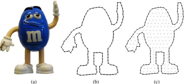
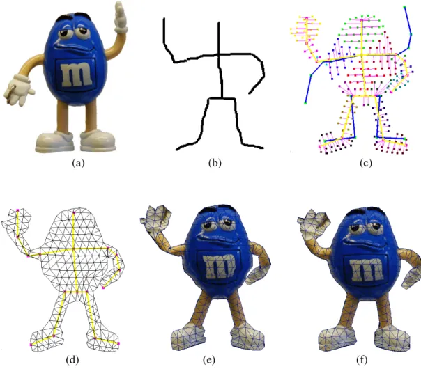
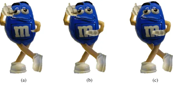
In the following, the technical detail is discussed and a popular cartoon figure: mm (Figure 3.1 (a)) is used to illustrate the result.
3.2 Silhouette Detection and Triangulation
As the input to our prototype cartoon generation system, the user first imports a 2D character serving as the original template model, which can be represented by BMP/JPEG or vector graphics format. The requirement is that the boundary of the object should be represented by a closed polygon. For BMP/JPEG images, the background is currently removed manually. Its silhouette is detected with the marching squares algorithm detailed below, forming a closed polygon (Figure 3.1 (b)). Then the discrete uniform sampling is conducted inside the silhouette (Figure 3.1 (c)) to make the distance between neighbour vertices almost equal.
Chapter 3. Sketch-based Skeleton-driven 2D Animation _________________________________________________________________________________
22
(a) (b) (c)
Figure 3.1 Experimental result of silhouette detection for a cartoon character. (a) Original image, (b) Vector graphic for silhouette, (c) Vertexes after discrete uniform sampling
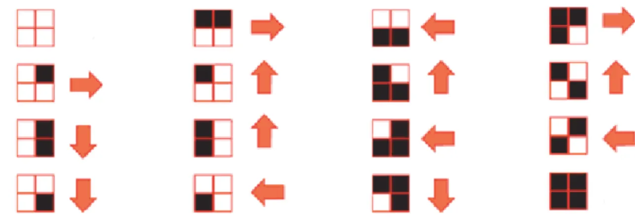
The marching squares algorithm for silhouette tracing is similar to the marching cubes algorithm [Lorensen and Cline 1987]. It can be described as follows. In the binary segmented image, assuming that the object consists of a set of black pixels and the background is white, the algorithm examines four adjacent pixels each time in a 2 x 2 grid. The search is anticlockwise. For any given position in the image, the 2 x 2 grid is in one of 16 possible cases shown in Figure 3.2. For example, if the grid is in the object, all pixels are black. If it is in the background, they would all be white. For positions on the edge of the object, the 2 x 2 grid belongs to other 14 cases which can be used to determine which position in the image is examined next as indicated by the arrow. The process is repeated until the test grid reaches its starting position. Then the silhouette is traced and the loop terminates.
Chapter 3. Sketch-based Skeleton-driven 2D Animation _________________________________________________________________________________
23
Figure 3.2 16 possible cases and direction of the moving 2 x 2 grid on the next iteration
Distributing discrete points allows the polygon to be triangulated. Many triangulation algorithms exist. Igarashi et al. [2005] used a particle based algorithm which performed better manipulation results by using near-equilateral triangles with similar sizes across the region. In our system, a simple but effective method is designed to achieve the same result. Starting with the standard Delaunay Triangulation [Shewchuk 2002]to connect all the vertices (including interior vertices and boundary vertices) (Figure 3.3 (a)), all the external triangles outside the boundary are classify and deleted to generate the final triangle meshes. This process achieves the same experimental result of the Constrained Delaunay Triangulation, which is shown in Figure 3.3 (b). The sampling density is adjustable at the user’s will to form sparser or denser meshes depending on the requirements. To make sure a character shape is properly triangulated, the template model should be expanded or the limb occlusion is solved beforehand using image completion techniques [Drori et al. 2003, Sun et al. 2004].
Chapter 3. Sketch-based Skeleton-driven 2D Animation _________________________________________________________________________________
24
(a) (b) Figure 3.3 Process of our designed Constrained Delaunay Triangulation. (a) Standard Delaunay Triangulation, (b) Final result after deleting the external triangles
3.3 Skeletonization and Decomposition
After the silhouette detection and triangulation, to guide the animation skeleton production, the curve skeleton (medial axis) of the model is first identified using a 2D thinning algorithm. This process is called skeletonization. In our system, the curve skeleton is generated by the Hilditch's thinning algorithm [Cornea, et al. 2006].
Hilditch’s thinning is an algorithm that can be used for a binary image. It can produce clean curve skeleton without unexpected needles or branches. It can be described as the following operations, which are based on the configurations of the neighbourhood for each pixel.
For a 3
×
3 pixel region which is shown in Figure 3.4, if P1=1(the centre pixel is black) and it is 8-neighbourhood of pixel P1 , the following four conditions are defined:Chapter 3. Sketch-based Skeleton-driven 2D Animation _________________________________________________________________________________ 25 2.
A P
( )
1=
1
3.P P P
2⋅
4⋅
8=
0
orA P
(
2)
=
1
4.P P P
2⋅
4⋅
6=
0
orA P
(
4)
=
1
Where
A P
( )
1 is the number of 0,1 patterns in the sequence 2P
,P
3,P
4,P
5,P
6,P
7,P
8,P
0 ,P
2.B P
( )
1 is the number of non-zero neighbours of 1P
. If all the four conditions above are satisfied, the pixelP
1will be removed (change black to white,P
1=
0
). This iteration is repeated until no more pixels can be removed in the binary image.3
P
P
2P
0 4P
P
1P
8 5P
P
6P
7Figure 3.4 3
×
3 pixel region in a binary imageTo produce an animation skeleton, the user locates the joints either on the curve skeleton or the mesh vertices. An example of the curve skeleton is shown in Figure 3.5 (a). Some end points of the curve skeleton branches (red points in Figure 3.5 (a)) can be used as skeletal joints directly. After skeletonization, every vertex is attached to its nearest skeleton segment. This is called the decomposition or skinning, which classifies the vertices into different parts. Our algorithm is similar to the KNN (K-Nearest-Neighbour) classification [Dasarathy 1991]. One important difference is that in our method when computing the minimum distance between vertices and skeleton segments, it should not be intersected with silhouette. This can be expressed as:
non-intersected
( )
imin{
( ,
i j)}, (
[1, ])
Chapter 3. Sketch-based Skeleton-driven 2D Animation _________________________________________________________________________________
26
where
non-intersecteddistance v segment( ,i j)denotes the Euclidean distance between vertex i
v
and the skeleton segment:segment
j, and it should not be intersected with silhouette of object; k represents the total number of skeleton segments.l v
( )
i gives the minimum among all the Euclidean distances between vertexv
i and the skeletonsegments:
segment
jj
∈
[1, ]
k
. Supposel v
( )
i is the distance between vertexv
iandskeleton segment:
segment
m, vertexv
iwill be attached tosegment
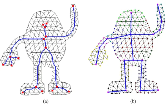
m and its new coordinates will be determined by the position of this skeleton segment during animation. The decomposition result for the example cartoon character is shown in Figure 3.5 (b). In this figure, there are 16 skeleton segments, which have been colour-coded to represent the associated vertex regions. As our method is based on the shortest distance classification, the decomposition algorithm may occasionally classify some vertices in a wrong region. The user can refine the final decomposition result through interactive adjustment (Section 6.3).
(a) (b)
Figure 3.5 Result of skeletonization and decomposition. (a) Curve skeleton, (b) Skeleton and decomposition
Based on the classification of all the vertices, triangles can now be classified into two types, interior triangles and joint triangles. If the three vertices of a triangle are
Chapter 3. Sketch-based Skeleton-driven 2D Animation _________________________________________________________________________________
27
of the same colour, i.e. they are all associated with one skeleton segment, the triangle is an interior triangle. Otherwise the triangle is a joint triangle. Both types of triangles are shown in Figure 3.6. Meanwhile, the vertices can also be sorted into three categories, silhouette vertices, interior vertices and joint vertices illustrated in Figure 3.6. Silhouette vertices form the contour of the object. Except for silhouette vertices, if all the neighbouring triangles of a vertex are interior triangles, this vertex is an interior vertex; otherwise it is a joint vertex.
Figure 3.6 Illustration of our definition for different types of vertices and triangles
3.4 2D Shape Deformation
Shape deformation is crucial to the quality of animation and it is an essential step in our technique. The main objective of our algorithm design is both to minimize the boundary change, interior shape distortion and computational overheads. A 2D character is deformed in two stages: skeleton driven deformation for each vertex region (Stage 1) and nonlinear deformation for the joint areas (Stage 2). For Stage 1, since the computation involves simple transformations, it incurs only a small overhead. Stage 2 minimizes implausible deformations. Although the computation is more complex, it involves only a small portion of the vertices.
3.4.1 The Variable-Length Needles Model
The variable-length needles model represents the geometry of the deformable object using a collection of variable-length needles. Each needle links a vertex to its attached skeleton segment. Each needle originates from the skeleton and extends
interior triangle
joint vertex joint triangle
silhouette vertex interior vertex
Chapter 3. Sketch-based Skeleton-driven 2D Animation _________________________________________________________________________________
28
outward in a fixed angle. The vertex is at the end point of a needle. The length of a needle l v( )i is the Euclidean distance between the vertex and the corresponding
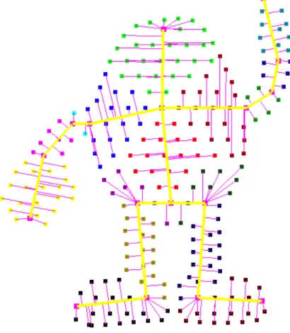
skeleton segment. The computation formula is given in (3.1). Figure 3.7 illustrates an example of the variable-length needles model.
Figure 3.7 Variable-length needles model for a cartoon character
3.4.2 Stage One: Skeleton Driven Deformation
In skeleton driven deformation, the geometry of all vertices is determined only by the position of the corresponding skeleton segment. Because the points are close to the skeletal segment, it is reasonable to regard the needles to be subject to the affine transformations of the skeleton segment during animation. Rotation and scaling are legitimate transformations here. During transformation, the length and direction of the needles relative to the skeleton segment are unchanged if the length of the skeleton segment is constant, leading to fast computation of the new coordinates of the mesh vertices.
Chapter 3. Sketch-based Skeleton-driven 2D Animation _________________________________________________________________________________
29
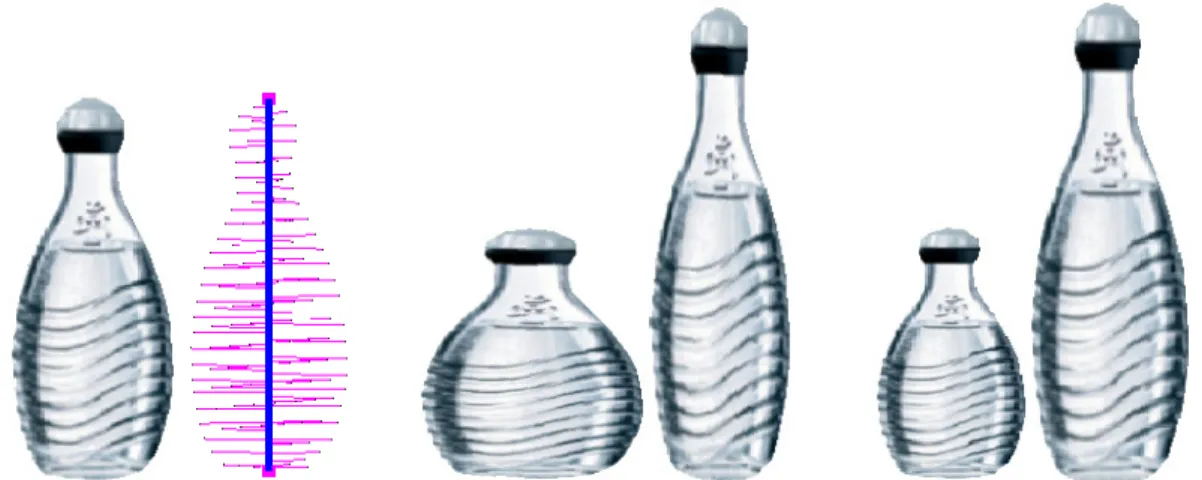
Cartoon characters often exhibit significant squashing and stretching deformations. An advantage of using our needle model is that the area enclosed by the boundary can be maintained mostly by ensuring the change of the length of a needle to be reciprocal of the change of the linked skeletal segment length. Because the needles cover the character’s surface, this simple method nearly preserve the global area of the character. Figure 3.8 demonstrate the effect of this global area preservation. One skeletal segment is used to deform the bottle. Our developed animation system supply two deformation options for users: One is with area preservation (middle). Another is without area preservation (right).
Figure 3.8 Deformation with (middle) and without (right) global area preservation. The original object and variable-length needle model are shown on the left
Figure 3.9 illustrates this deformation process. As can be seen in Figure 3.9 (e), the deformation is quite realistic. However, the texture and contour curve in some joint areas is not sufficiently smooth, and some joint triangles even overlap. This suggests that to minimize shape distortion, the joint areas need to be concentrated and ensured the deformation conforms to the original model. Here some important geometric properties of the 2D model shape, such as the local shape features of the contour, the interior shape smoothness and local area need to be preserved. This process is described in the next section.
Chapter 3. Sketch-based Skeleton-driven 2D Animation _________________________________________________________________________________ 30 (a) (b) (c) (d) (e) (f)
Figure 3.9 Deformation process. (a) Original character, (b) Sketched skeleton, (c) Deformed character displayed as a variable-length needle model. The blue lines represent the skeleton of the original template model before deformation, (d) Mesh and skeleton after the deformation of Stage one, (e) Character after the deformation of Stage one, (f) Character after the deformation of Stage two
3.4.3
Stage Two: Nonlinear Deformation in Joint Areas
As mentioned in Related Work, there are quite few approaches on shape deformation, such as FFD (Free Form Deformation), physically-based method. Here, as it is without parameter setting and fast in convergence, the gradient domain techniques are applied to solve deformation as an energy minimization problem.
The energy function usually contains a term for a position constraint and a term for a detail-preserving constraint. The detail-preserving constraint is usually nonlinear
Chapter 3. Sketch-based Skeleton-driven 2D Animation _________________________________________________________________________________
31
because it involves both the differentials for local details and the local transformations which are position dependent. Three geometric constraints are employed to prevent shape distortion. They are: rotation and scale invariant (RSI) Laplacian coordinates [Sorkine 2004]; mean value coordinates [Floater 2003] and edge length of the triangular mesh. The first constraint preserves the local shape feature of the contour curve; the second constraint preserves the interior smoothness; the third are used to achieve local area preservation [Weng et al. 2006]. Our algorithm can be viewed as a combination of three linear and nonlinear optimizations.
Let (
V
,E
) be the 2D graph of a character’s mesh model, where V andE
are the sets of vertices and edges respectively.V
can be divided into three subsets: silhouette vertices:V
s, joint vertices:
V
p and joint vertices:V
q. Assumes that thequantity of vertices is
n
,V
s containsk
silhouette vertices,V
p containsm
joint vertices, andV
q containsn m k
−
−
interior vertices. In Stage two, the coordinates of all the interior vertices are fixed. As discussed earlier, the RSI Laplacian coordinates are used to minimize the silhouette distortion in the joint areas. The mean value coordinates are used to minimize the shape distortion of the joint areas. And the edge length of triangular mesh is used to minimize the local area change.a. RSI Laplacian Coordinates
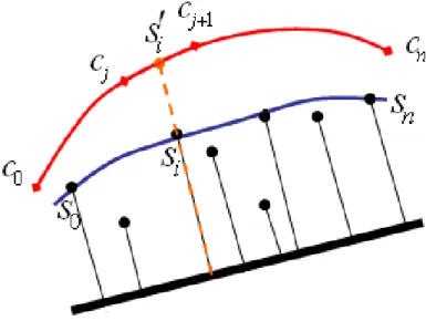
The curve Laplacian coordinate of vertex
v
i is computed using the equation (3.2) below, which formulates the difference with the average of its neighbouring vertices.δ
i=
Lp v
( )
i=
v
i−
(
v
i−1+
v
i+1) /
2 (3.2)Lp is called the Laplace operator of the curve.