P.L.A.N.R.
Planar Learning Autonomous Navigation Robot
Senior Project Report
June 13, 2019
Gabby Santamorena
[email protected]
Chuy Mercado
[email protected]
Daniel Kasman
[email protected]
Ben Klave
[email protected]
Andrew Weisman
[email protected]
Table of Contents
Introduction
. . . . 2
Problem Statement
.
. . . 2
Software
. . . . 3
Image Recognition .
. . . 3
ROS Systems .
. . . 4
Arduino .
. . . . 7
Hardware
.
. . . 9
System Topology .
. . .
. . .
. . . 9
Camera - Orbbec Astra Pro .
. . . 10
LiDAR - Slamtec RPLiDAR A3 .
. . . . 11
Jetson .
. . . 12
Arduino .
. . . . 12
Mechanical
.
. . . . 13
Structural .
. . . . 13
Motors .
. . . 14
Bill of Materials
.
. . . 15
Lessons Learned
. . . . 16
Conclusion
.
. . . 18
Appendix
. . . 19
Documentation
.
. . . 27
Image Recognition . . . 27
Operating PLANR . . . 32
ROS . . . 34
Introduction
Working with an architecture company, TEECOM, our team of six Cal Poly Computer Engineering students came together to create a product which facilitates the work done by the company. Through constant communication with TEECOM’s research and development division, our team was able to meet the needs of the company and gain context for how the product will be used. TEECOM works with companies to outfit business areas with technology ranging from wall-sized screen displays to webcams in meeting rooms. In order to plan how a space will look and how it will be organized, they create building floor plans. In order to make this process more efficient, the Planar Learning Autonomous Navigation Robot (PLANR) was created.
PLANR is a self-contained robot capable of mapping a space and generating 2D floor plans of a building while identifying objects of interest. It runs Robot Operating System (ROS) and houses four main hardware components. An Arduino Mega board handles the navigation, while an NVIDIA Jetson TX2, holds most of the processing power and runs ROS. An Orbbec Astra Pro stereoscopic camera is used for recognition of doors, windows and outlets and the RPLiDAR A3 laser scanner is able to give depth for wall detection and dimension measurements. The robot is intended to operate autonomously and without constant human monitoring or intervention. The user is responsible for booting up the robot and
extracting the map via SSH before shutting down.
Problem Statement
TEECOM, along with most smart space designers and general contractors, rely heavily on a buildings floor plan or blueprints to make design decisions. An issue that TEECOM has experienced is having to generate their own floor plan due to the previous floor plan being inaccurate or inaccessible. PLANR is an all-in-one solution for this problem as it can generate as built drawings of any building and only requires access to the building. This product aims to expedite TEECOM’s workflow. With these accurate floor plans, TEECOM will be able to begin planning and designing office spaces sooner, without having to physically travel to the building. The addition of features such as including doors, windows, and electrical outlets, allows the company to plan ahead as they gain a better layout of the space to make more permanent design decisions earlier on.
Software
Image Recognition - YOLOv3
For our image recognition system, we chose to use the You Only Look Once (YOLO) framework developed by Joseph Redmon, specifically YOLOv3. There were a few factors that led to us choosing YOLO over other, more conventional, methods. First and foremost, YOLO is a free, open-source project. Second, YOLO’s unique neural network construction allows it to be much faster than regional
classification methods, such as R-CNN (regional convolutional neural network) and other systems more commonly used for image recognition. The speed of our image recognition software was very important as we knew there was going to be a lot of data to scan through for each completed floor-mapping. Finally, since the objects TEECOM requested we identify (doors, windows, power-outlets, and ethernet ports) aren’t part of any traditional image recognition data sets, we wanted to use a system in which training custom networks was relatively easy.
Image 1: Example of YOLOv3 Detection
As mentioned above, the objects TEECOM was interested in are not part of any common data set, so we had to train a custom neural network to fit our needs. The training process was a pretty standard classification training method. First we pulled thousands of training and testing images from the web, boxed the areas of interest in all images, modified a handful of text files for training, and then let the built-in YOLO training command handle the rest. A detailed description of the training process can be found in the User Manual at the end of this document. Once the tedious training process was complete, we had a weights file for our custom trained model.
Since processing images or video frames with YOLO is somewhat time-intensive, we opted to do all of our image recognition after the robot had finished mapping a floor rather than running YOLO as the robot is exploring. To do this, we wrote a simple bash script which used the unix “streamer” command to take and save pictures at set intervals (currently once a second) throughout the duration of the mapping. Once the mapping is complete, a message is passed within ROS to signal the camera to stop taking pictures. Then, once the mapping is complete and all the images have been recorded, a second bash script is launched that runs each recorded image through our image recognition neural network. If a detection is made, the time that image was taken, the type of object found, and the location of the object within the frame are recorded in a text file. Once this script finishes, this text file will have a list of all the objects recognized throughout the robot’s exploration.
While we came a long way in terms of implementing our image recognition system, there is still a good deal of work that can, and most likely will, be done by a future team. First and foremost, the quality of our neural network can be improved by adding images to the training set. Currently our system is operating at about 95% precision (not getting many false positives) but only 70% recall. This means about 30% of images that should be recognized are not. Adding to our training set and re-training is a monotonous but simple task which, for the sake of time, we chose not to go too deep into.
The second, and final thing that we didn’t have time to accomplish was actually placing the locations of detected objects on a final map. We currently have all the data necessary to do this, but did not have enough time to actually implement it. For every detection in our output log, we can take the timestamp to find the location of the robot at that time. Then, we have the location of the object within the frame, so some simple geometric calculations can be made to approximate the angle from the robot which the object appeared. Since all our objects appear on walls, we can follow that calculated angle and drop a labeled point on the wall in our map.
ROS Systems
Robot Operating System (ROS) is a robotics middleware that enables low-level device control, software package management, and message passing between processes, which makes it flexible and applicable to a broad range of robotics applications. We chose to use ROS because PLANR is built on coordinating communication between multiple sensors in order to autonomously map an indoor space. PLANR also incorporates a networking aspect: movement commands are sent from a connected computer to the robot, and the robot reports status information back to the connected computer.
ROS was the clear choice based on those two requirements. Additionally, there are many
open-source projects (called “packages” in ROS) that were built to work with the exact sensors that were chosen for the robot.
Our system utilizes these main message types:
transform: maintains reference frames of our robot and the scanned environment odometry: reports the current linear and angular velocities of the robot
laserScan: generated by our LiDAR scanner, reporting range and angle data to create an image of the robot’s surroundings.
map: the output of our system; built by gmapping node using laserScan and odometry To move the robot, we built a python script that polls for keyboard input from a computer
connected over ssh. Key commands are converted into ROS twist messages and are sent to the Arduino Mega using the rosserial package, and the Arduino decodes those messages into motor control. The Arduino also continually reports odometry information to the Jetson.
To build a map of the environment, we are using the slam_gmapping node, a ROS wrapper around OpenSlam’s Gmapping implementation that enables Simultaneous Localization and Mapping (SLAM). This package works by combining laser scan information from our LiDAR sensor and odometry from the motor control system to keep track of our robot’s location within the world.
Image 3 shows an early map that we captured using a ROS package called hector_mapping. This package uses a SLAM algorithm to track the robot within its environment while generating a map.
Image 3: Hector_mapping package output
Hector_mapping does not use odometry data to assist in localization. As a result, it has difficulties localizing the robot in areas without well defined topographical features. It mapped a single room very well but was extremely unreliable in the hallway outside the room.
After experimenting with hector_mapping, the development process moved to working with the slam_gmapping node. Slam_gmapping can take advantage of our robot’s odometry data to assist in localization. Image 4 shows a map from one of our first tests of slam_gmapping.
Image 4: Early test results of slam_gmapping ROS node
This map turned out poorly due to calibration issues with the odometry data. Slam_gmapping received conflicting data from the internal SLAM algorithm and our odometry data. Our data reported that we had moved a very large distance while SLAM determined that we had only moved a few feet. The SLAM algorithm’s interpretation was correct. After scaling down the data and tuning the robots movements, we got a much better result, shown in Image 5.
Image 5: Localization slippage with slam_gmapping
The map in Image 5 is much cleaner than that of Image 4, but still has several issues. First, the odometry data is still not perfectly calibrated, leading to the crooked appearance of the room. Second, the system still experienced slippage in a long hallway. Both of these issues can easily be rectified with the use of an Inertial Measurement Unit (IMU). An IMU uses an accelerometer and gyroscope to
measure movements of system. The slam_gmapping package supports a combination of odometry and IMU data to assist in localization. We realized too late into the project that this would be helpful and ran out of time to implement the functionality. This is a top priority feature for future teams to implement, and the framework we have laid out should make it very easy.
The slam_gmapping node outputs a .pgm file that contains data about free space and obstacles in the room. Future groups can overlay data from the image recognition systems onto this .pgm file by using timestamps to determine the robot’s position at the time the image was taken. If a desired object (door, outlet, etc.) is detected, that data will be overlaid on the map image.
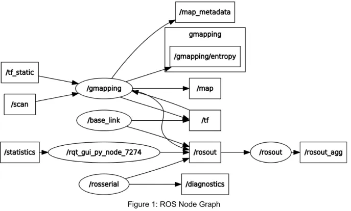
The following graph describes the communication between each node in our system. ROS nodes (ovals) communicate by either subscribing to and/or publishing to topics (boxes).
Figure 1: ROS Node Graph
Arduino
We chose to use an Arduino as the main drive control computer because of the wide variety of open source code libraries available in the Arduino ecosystem. Throughout the development process, these libraries allowed us to quickly test new features such as infrared remote control, magnetometer assisted turns, and Proportional-Integral-Derivative (PID) control. The ability to quickly prototype new features allowed us to have better demonstrations and to discover techniques that would and would not work for the robot.
One of the first features we implemented on the Arduino was PID control. PID is a mathematical method by which inputs can carefully adjust the outputs of a system. In our case, we used wheel
encoders to determine which of the two wheels was spinning faster. Wheel encoders measure how much a wheel has rotated and report the data via software. By balancing the speeds of the two wheels, we were able to make the robot move in perfectly straight lines. Without this control, the two motors would naturally spin at different speeds and the robot would drive in an unpredictable manner. This feature is still present in the final product but has constantly evolved over the course of the project.
Another key feature for the robot is remote control. The entire point of the project was to not have a person walking around with a camera or measuring tape, so we tackled this problem early in the development process. Our first method consisted of an infrared sensor mounted on the robot and an infrared remote for the operator. The infrared sensor was interfaced to the Arduino via a library that read in pulse-width-modulated (PWM) waveforms. This system behaved much like a television remote. It only worked in direct line-of-sight and would often need multiple button presses for a command to be
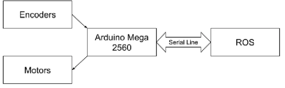
registered. This was acceptable for development and prototyping, but not for a final product. We replaced this system with a serial communication line between the Nvidia Jetson TX2 board and the Arduino. The ROS instance running on the Jetson now sends movement commands along the serial line for the Arduino to execute. This solution is much more elegant because the ROS instance can be controlled remotely and wirelessly from another computer. An operator with an internet connection is able to send a command from a laptop to ROS. ROS will then relay the command over the serial bus to the Arduino. There is no more line of sight requirement and the loss of commands is minimal.
Figure 2: Block Diagram of Arduino Software
One of the now-deprecated features is the magnetometer-assisted turns. We originally wanted to give the Arduino extremely fine control over the robot’s rotational position using a magnetometer. A magnetometer senses the ambient magnetic field to determine the direction of magnetic north. Using magnetic north as a reference allows one to know an accurate rotational orientation. The sensor we ordered was an MPU9265 accelerometer and gyroscope with a magnetometer add-on. This was
interfaced to the Arduino using Serial Peripheral Interface (SPI). The magnetometer worked well for large turns, but due to its low sampling rate of 1Hz, it was unable to perform accurate small turns. There were also concerns about the local magnetic field being influenced by the motors and large battery. A future improvement to the robot would be to find a more sensitive magnetometer and provide adequate shielding for it from possible noise sources. The turns are currently performed by adjusting the robots rotational position while counting specific numbers of encoder ticks. This is acceptable for manual driving, but it is not flexible and should be re-worked in the future, especially if autonomous navigation is to be implemented.
One of the main challenges faced during the development of the Arduino software was finding a way to compensate for the unreliable wheel encoders. We were never able to find a consistent wheel rotation to encoder tick ratio, which made it difficult to perform calculations involving the encoders. The only documentation for the motor-encoder combination hardware that we could find offered no guidance. Turns, PID control, and odometry data were all extremely difficult to debug since we had no concrete representation of what one encoder tick looked like. We consistently had to “guess and check” arbitrary
encoder values that represented a more concrete value, such as a 90 degree turn. Through these
difficulties we learned that nothing should be assumed to be reliable. In retrospect, we should have taken advantage of our budget and purchased better hardware. This would have effectively saved money and time.
Hardware
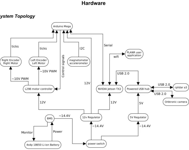
System Topology
Figure 3: Electrical System Diagram
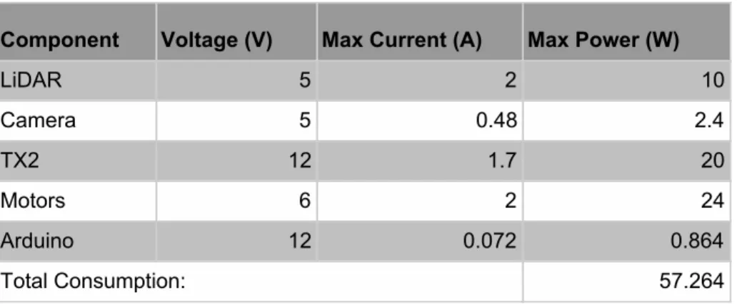
The figure above shows the overall topology of the robot system. The battery selected was based off of the client’s specifications that the robot should be able to run for at least three hours on a single charge. The calculations for total power consumption is based off the calculations shown in Table 1 below. Table 1 displays the power consumption of the individual system components based off of their respective data sheets.
Table 1: Power Consumption of System Components Component Voltage (V) Max Current (A) Max Power (W)
LiDAR 5 2 10 Camera 5 0.48 2.4 TX2 12 1.7 20 Motors 6 2 24 Arduino 12 0.072 0.864 Total Consumption: 57.264
Camera - Orbbec Astra Pro
To recognize doors, windows, and outlets using image recognition, the Orbbec Astra Pro camera was selected. Using the Orbbec Astra Pro, a video is taken as the robot navigates a room or floor. For each frame taken by the camera, a timestamp of when the frame is taken is recorded by the robot. During post processing, the GPU on the robot will take each frame and run it through the neural network and see if any doors, windows, or outlets are detected in the photo. If so, that location on the floor plan will be marked with an indicator of that object by using the time the photo was taken and the location of the robot at that time.
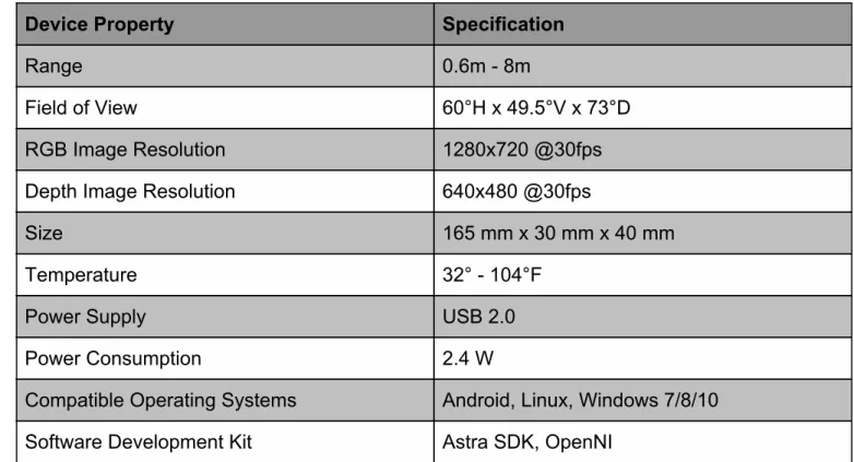
This camera has a range of .6-8 meters, and large field of view, 1280x780 RGB resolution, and can be powered by USB 2.0, making it a good fit for the project. This camera was also selected because it contains both an RGB camera and a depth camera. The depth data from this camera can be used to determine the size of the doors, windows and outlets, as well as help determine the location of the robot relative to a wall.
Lastly, this camera was selected because of its advertised software development kit, Astra SDK. This SDK was not easy to set up or use, but we were unaware of this until after we already had received the camera. There is minimal documentation online on how to use the camera, and the Astra SDK for the camera did not have any drivers for using the RGB camera. This led us to use third party drivers from GitHub, which was not preferred. The specifications for the robot are listed below in the Orbbec Astra Pro Camera Specifications Table.
Table 2: Orbbec Astra Pro Camera Specifications Table
Device Property
Specification
Range
0.6m - 8m
Field of View
60°H x 49.5°V x 73°D
RGB Image Resolution
1280x720 @30fps
Depth Image Resolution
640x480 @30fps
Size
165 mm x 30 mm x 40 mm
Temperature
32° - 104°F
Power Supply
USB 2.0
Power Consumption
2.4 W
Compatible Operating Systems
Android, Linux, Windows 7/8/10
Software Development Kit
Astra SDK, OpenNI
LiDAR - Slamtec RPLiDAR A3
Choosing a sensor for generating our map was the most important consideration for this project. There were two main types of sensors that we considered: LiDAR and Structured Light, a type of sensor that projects a known grid pattern onto a surface and then uses a camera to measure the distortion of the pattern. LiDAR generally offers better accuracy than Structured Light sensors such as Intel’s RealSense cameras, but only scans in two dimensions (360°) at our budget level. An additional benefit of structured light sensors are that they include an RGB camera which could potentially be used for our image
recognition purposes as well. All things considered, we prioritized accuracy over the other
characteristics, so we were leaning towards LiDAR from an early stage. After researching a variety of LiDAR sensors in our price range, we decided on the Slamtec RPLIDAR A3 360° Laser Scanner.
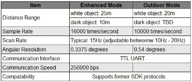
We chose this specific LiDAR sensor as many online reviews lauded this particular model as the best LiDAR sensor under $1000. Since we initially didn’t have a clear idea of how much our entire project would cost, we thought it was good to go with this option over a more expensive option. Besides cost, there were a few specifications that further convinced us to choose the A3 sensor. The specifications that were particularly important to us were the high polling rate, which helped give us the accuracy TEECOM desired, the 25m range which would likely ensure the entire room could be “seen” regardless of the path the robot chose to take, and finally the relatively extensive SDK for the sensor which helped when using the sensor for the first few times.
Table 3: RPLIDAR A3 Specifications Table
Jetson TX2 Developer Board
We chose to use the Jetson TX2 Dev Board after failures of implementing our system using the Raspberry Pi 3. We struggled for a while getting all of the desired ROS packages to function on the Raspberry Pi, as most of the ROS software is developed for Ubuntu, meaning we couldn’t use any precompiled binaries for our packages in Raspbian. This should not have been a problem, but we found that there were many compile time errors while compiling the hundreds of packages we needed, and we spent a long time trying to get the whole ROS system to function how we needed it to. We decided on switching to the TX2 due to its ease of implementation, and impressive computational power. We were able to get our whole ROS system to work on the TX2 in minutes instead of days, so ultimately it was a great decision to make the switch. Further the power of the TX2 allows us to do all post processing on PLANR, after all data has been collected. The board can be powered anywhere between 9-19V which means we can easily run it off of our LiPo battery. The only real downside of the TX2 development board is the lack of USB ports, so we were forced to get a powered USB hub. There was also additional
difficulty in loading the CUDA drivers for the image recognition, due to a somewhat convoluted method of putting them on the TX2.
Arduino
We chose an Arduino Mega 2560 to be our drive system computer. We chose an Arduino branded microcontroller for the wide availability of software libraries. This specific Arduino board has a wide array of general purpose input/output (GPIO) ports for all of the various sensors we could have chosen to use. At certain points we easily had over 25 wires connected to the board at a time. Not many other boards can comfortably support that level of connectivity. The board can be powered via USB, which is convenient for development. This allowed us to easily reprogram the Arduino from the Nvidia Jetson TX2. Lastly, the board is very cheap at only $38. There are also alternatively branded copies for less.
There are some trade-offs that had to be considered with this board. First and foremost, the board is relatively large. There are many smaller boards that we could have used instead. However, once the Nvidia Jetson TX2 was involved with the project, it instead became the main bottleneck in terms of layout space. When the robot body was redesigned to fit the Jetson, the now comparatively small Arduino Mega 2560 became a non-issue. The on-board Mega 2560 processor is also relatively slow at only 16MHz. This performance trade-off was acceptable because we intended to use a second main computer (Nvidia Jetson TX2) that was much faster for any computationally heavy tasks. We would only use the Arduino for reading sensors and operating the motors.
Mechanical
Structural
PLANR’s body is based on a design by Cal Poly Professor Dr. Smith. Our robot’s body consists primarily of laser cut acrylic plates, spaced apart by approximately 50 millimeter long metal standoffs. All of the M3 screws we used were selected to fit in the approximately 3.5 millimeter wide mounting holes. We custom designed each of the four body plates to accommodate mounting points for all of our
hardware. The templates were designed in Inkscape and sent to a laser cutting service offered by Pololu Robotics & Electronics. (See Appendix for full images and hardware layout) The approximate dimensions of the plates are 8x10 inches and 3 millimeters thick. The approximate dimensions of PLANR are 11 inches wide by 10 inches long by 12 inches tall.
Figure 4: PLANR Body Plates [Top (left) to Bottom (right)]. High-Resolution on Page 19. The robot balances on its two wheels and a ball-bearing leg mounted in the back. We have noticed that the bottom-most layer of acrylic bows around the wheels’ axis. This is due to the significant weight increase without a significant change to the support system. We estimate that Dr. Smith’s original design weighed about 3 pounds, but PLANR weighs 10 pounds. Due to the weight distribution of the robot, it is possible for it to briefly tip forward. Both the bowing acrylic issue and the balance issue could easily be easily rectified by future teams by adding another ball bearing leg to the front of the robot. A four-wheel drive system would be ideal, but is not necessary for this application.
Image 6: Comparison of Old (left) and New (right) Structural Designs
Motors
PLANR’s two motors are powered with 14.8V DC and come with built in motor encoders. These motors were originally used in Dr. Smith’s design. We considered upgrading them to models with more power, but we never found their power output to be an issue. The two motors provided more than
enough power for our much heavier and modified robot. They are forward-mounted and are affixed to the underside of the bottom acrylic plate using an L shaped bracket. These motors should have been
replaced early on due to the unreliability of the encoders. As discussed in the section on Arduino Software, unreliable hardware cost the team many hours of development time.
Bill of Materials
Table 4: Final Product Bill of Materials
#
Quantity
Item
Price
1 1 RPLiDAR A3 $599.00
2 1 Orbbec Astra Pro $159.99
3 1 Nvidia Jetson TX2 Developer Kit $347.48
4 1 Arduino MEGA2560 $14.99
5 2 Motors with encoder $69.90
6 2 Wheels N/A
7 1 H Bridge $9.68
8 1 Lipo Battery Pack $63.99
9 1 5V Voltage Regulator $15.99
10 1 Balance Charger $15.34
11 1 USB Data Hub 17.99
12 12 Hex Standoff $8.38
13 1 M3 kit $10.86
14 1 Micro USB Cable $3.33
15 2 XT60 Female to Bare Wire $7.99
16 1 22 Gauge Wire $15.99
17 1 14 Gauge Wire 15.99
18 1 Velcro $7.47
19 1 AC Power Supply $15.90
20 1 Nvidia Power Cord $6.20
21 4 Acrylic sheets $117.20
22 1 LiPo Battery Manager $21.55
23 1 BMS 14.8V Battery Protection $7.49
Lessons Learned
Gabby -
The biggest lesson I have learned is that everything on the project schedule should be given approximately three times the amount of time originally estimated. The original project schedule we created did not account for things not going smoothly. It was overly ambitious for the timeline we had. I spent most of my time working on the image recognition part of the project. Since we were using an open source library, we thought that we would be able to get the neural network trained and working within two weeks. It actually took about two months to figure out why it was not recognizing anything. Another lesson I have learned is that project work should be delegated in a way so that one person being stuck on a portion of the project does not roadblock the whole thing. We ran into a few situations in which this happened this year, but overall as a team we were able to organize ourselves in a way that avoided this.Daniel -
I learned a wide variety of technical and project management skills. I came into this project expecting to apply my knowledge of embedded systems to yet another project. I quickly learned that there is so much more to robotics than some low level coding. I gained experience in industry grade RTOS tools like ROS, image recognition libraries, graphic and mechanical design, electrical power systems, and control systems. These tools will be a great asset in my career and have made me a very well rounded engineer. I also learned what it takes to organize large engineering projects. It takes months of design and planning, regular meetings, some more redesigning, and far more implementation time that I would ever guess. Everything will take longer than I think it will. Hopefully as I become a more experienced individual, my estimates can be more accurate. Looking back, I had no idea what I was getting myself into but I wouldn’t trade the experience for anything. This was a perfect example of a real world, multidisciplinary, research and development project that has made me a better engineer.Ben -
This project was taught me a lot over the past year. From a technical perspective, I learned a lot about computer vision, image recognition and machine learning in general. However, while the new technical knowledge was both interesting and useful, I believe the biggest takeaways for me were in regards to teamwork and project management. Early on in this project I learned a lot about how to deal with a client, TEECOM in our case. Since we were given very little direction at the start of this project, we had to discuss and explain all design decisions with our TEECOM contact in detail. We often had to push back to balance their desires with what we realistically would have time to do. These skills of working with a client throughout the design process will likely we valuable moving forward in my career.Additionally, this project taught me the importance of developing an achievable schedule and planning out a project so that everyone can work on various pieces simultaneously, so no one is ever waiting on someone for too long to be able to do their part. All things considered, I learned so much this year and am grateful to have had this project for Capstone/Senior Project.
Chuy
-
When the team decided to take on this project at the beginning of the school year, I don’t think any of us knew how much work would be put into this project. Fortunately, we were able to take it as a learning experience and gain skills that are applicable to our careers after college. This project required more than functionality; we were forced to think of any legal issues that may present themselves, or how the user may not follow the suggested use cases. I also learned to make smart financial decisions in order to make the most out of the budget instead of relying on expensive pre-assembled robot kits. On a technical side, I was able to learn how the arduino operated as well as diving deep into PID controllers toensure the robot drove in the right direction. Along the way I was able to also get a general
understanding of how the lidar sensor generates data, how ROS put nodes together, and how a neural network can be trained. Although it might not seem like it, I believe the most useful thing I learned was to work independently without constant support from an instructor. There was no solution manual or guide to follow; it was on the team to set deadlines and make all the decisions. If I could go back and do things differently, I believe I would set more realistic deadlines, and put a lot more time into research before making design decisions or purchasing materials. Overall, this was a great opportunity for growth as we start our careers and I’m glad I joined this team.
Andrew
-
This project was my first foray into real-world engineering and product development, and I have learned a lot since Fall quarter. The first two quarters in Capstone taught me some of the many important aspects of product development, including: project management (through the use of Gantt charts), effective client communication techniques, and risk analysis methods such as FMEA, to name just a few things. The final quarter, despite the lack a traditional class structure, taught me just as many important lessons. Communication between our team and our client and our advisor was emphasized and it was our responsibility to communicate any issues and changes in project scope. Our work ethic was also challenged without a rigid schedule, but our team did a great job of maintaining a balanced work schedule. That said, this project also taught me to expect obstacles during development and the importance of rapid adaptation. For example, at one point, our main development board needed to be updated to accommodate our image recognition software, but the update process took multiple work sessions to complete. This left the ROS team to develop on our personal systems, which made me realize the importance of parallelizing our workflow. I also gained lots of valuable technical experience with robotics concepts. I learned an incredible amount in total this year, all of which is valuable in finding jobs and working in industry.Anthony -
Overall this project has been a great learning experience. ROS all though frustrating to work with is a very flexible and powerful environment with a ton of community support, and as far as technical skills was one of the most useful things I learned. More importantly than technical skills though islearning how to work with a team on a single system. Workflow needs to always be taken into account, that is if you are working on something that the whole team needs to wait for to continue development, then you need to get that done as soon as possible. Other aspects to take into account are things like complexity, and functionality of the implementation. When you have a timeline you may need to go with a less complex solution to accommodate base functionality. This project has been a lot of fun to work on if not a little frustrating at times, but overall it has given me a good idea of real world product development.
Conclusion
Overall this project has been a great learning experience. Coming into this project no single team member had an idea of how we were going to get this to work. The PLANR system works to map out rooms, detect objects in the room, and overlay those objects into a map. Further development is needed to implement autonomous navigation, and further testing is required to determine the accuracy and precision of the measurements taken. Further development in 3D mapping technology can also be explored but the current PLANR system would need to be heavily reworked to implement this
functionality. For anyone further developing this system it is highly recommended that you familiarize yourself with all of the subsystems of PLANR. YOLO and ROS in particular are very deep rabbit holes, and it is recommended that you become familiar with how to use them before further developing PLANR. This has been a great, and frustrating project to work on, and I hope the best of luck for any continuing developers.
Appendix
Image Recognition Documentation
Darknet Yolo Installation:
For our image recognition system, we chose to use the You Only Look Once (YOLO) framework
developed by Joseph Redmon. There were a few factors that led to us choosing YOLO over other, more conventional, methods. First and foremost, YOLO is a free, open-source project. Second, YOLO’s unique neural network construction allows it to be much faster than R-CNN (regional convolutional neural
network) and other common systems for image recognition. Finally, since the objects TEECOM
requested we identify aren’t part of any traditional image recognition data sets, we wanted a system that made training custom networks relatively easy. Below are the steps for training our YOLO network: Note: Training the YOLO neural network (or just working with neural networks in general) takes a lot of processing power so we would recommend not doing this on a personal machine. If working with the robot, you can ssh into the jetson and work directly from there. Otherwise, we found that the machines in 20-127 are decently fast. To use these machines ssh into the csc unix server (ssh
username@unix#.csc.calpoly.edu) and then from there ssh into username@127x0#(we used 9).csc.calpoly.edu. On these machines you can create a shared folder in the /vm directory, this way multiple team-members can access the material.
- Download Darknet from Github
- git clone https://github.com/pjreddie/darknet - cd darknet
- Go into the makefile and set GPU = 1 - Make
- Download the YOLOv3 weights file
- wget https://pjreddie.com/media/files/yolov3.weights - Assemble (or add to) training sets:
- In order to train the neural network, you are going to want as many images as possible for each of the desired classes (doors, windows, power outlets, ethernet outlets). We left off with about 400 images per class. Since compiling training sets is very tedious, use some web-scraping utility to pull batches of images. We used a python tool called
googleimagesdownload. Install this in one of the following ways: - pip install google_images_download OR
- git clone https://github.com/hardikvasa/google-images-download.git cd google-images-download && sudo python setup.py install - To actually use the tool:
- googleimagesdownload --keywords “wall socket“ --size medium -l 300 --chromedriver ./chromedriver (all one line)
- Replace “wall socket” with what you want to search on Google Images and replace 300 with the number of images you want from that search (I would recommend using multiple similar search terms with smaller number of images, over pulling all from one search).
- This will place the images in ./downloads/keyword (ie. wall socket) - Next you need to put all the pulled images in the right format
- First download the ImageMagick package - sudo apt-get install imagemagick - Convert all images to JPEG’s (not jpeg or JPG)
- mogrify -format JPEG *.jpg
- Note: this command creates a duplicate JPEG, so you will need to delete all the original, not JPEG images
- rm *.jpg, rm *.png, etc.
- In order to train YOLO, you will need to manually box (highlight) where the objects of interest are in all of the images you’ve obtained. We used the Yolo_mark tool to help with the marking process (don’t use BBox-Label-Tool as some tutorials will suggest).
- Download Yolo_mark : git pull https://github.com/AlexeyAB/Yolo_mark.git - Delete all files in the directory x64/Release/data/img
- Move all .jpg images to the cleared directory
- Change the number of classes (types of objects being recognized) in the file x64/Release/data/obj.data
- Put names of object classes (one per line) in the file x64/Release/data/obj.names - Finally, run x64\Release\yolo_mark.cmd to begin boxing
- Make sure when placing boxes, the number used the box number that corresponds to the index of the object in darknet/cfg/obj.names
- Next, upload the images to the darknet/data directory on the jetson
- For the next part, we followed this tutorial for training the neural network on multiple objects:
- https://medium.com/@manivannan_data/how-to-train-yolov3-to-detect-custom-obj ects-ccbcafeb13d2
- Download the 76 MB weights file from the tutorial as to train: https://pjreddie.com/media/files/darknet53.conv.74
- create a cfg/obj.data file: -classes = 4 train = train.txt test = test.txt names = obj.names backup = backup/ - Create an cfg/obj.names file:
- This will make the outlet class correspond to number 0, ethernet to 1, door to 2 and window to 3
outlet ethernet door window
- If you have not done so already, run the process.py script found here:
https://medium.com/@manivannan_data/how-to-train-yolov2-to-detect-custom-obj ects-9010df784f36
- What this script does is it generates the test.txt and train.txt files, which contain the name of each image you will use to train and test the neural network.
- Modify the
'<Your Dataset Path>'
line to be the path to your images that you have already placed boxes around.- Next, make the changes to the yolov3.cfg configuration file as specified in step 2 of the tutorial.
- Now you can begin training the neural net. - To begin training run:
./darknet detector train cfg/<whatever-yours-is-called>.data
cfg/<whatever-yours-is-called>.cfg darknet53.conv.74 (all one line)
- Note: if you have any issues with cuda running out of memory, you will want to modify the batch and subdivision fields at the top of yolov3.cfg (likely want to lower batch and raise subdivisions).
- Note: updated weight files are saved every 100 iterations through 900 and then saved every 10,000 after that (is you want to modify this change line 136 in /darknet/examples/detector.c)
- You are going to want to allow this training to run for a long time - Testing with a trained neural network:
- Once you have trained the YOLO network, the following command can be used to test your image recognition network on an image:
./darknet detector test cfg/obj.data cfg/yolov3.cfg <your_weights_file> <your_image>
- In order to easily run multiple images through the neural network, we wrote a simple bash script which will loop through all jpegs in a given directory, passing each image through the YOLO network and outputting the results to log.txt. This script can be found on the jetson at /home/nvidia/Darknet/darknet/test.sh. - Below is an example of log.txt created when running test.sh
0 /home/nvidia/.ros/155977709493359.jpeg
/home/nvidia/.ros/155977709493359.jpeg: Predicted in 1.488719 seconds. outlet: 85%
outlet : (230, 636)
_____________________________________________________________ 1 /home/nvidia/.ros/155977709739083.jpeg
/home/nvidia/.ros/155977709739083.jpeg: Predicted in 1.157667 seconds. _____________________________________________________________ 2 /home/nvidia/.ros/155977709921047.jpeg
/home/nvidia/.ros/155977709921047.jpeg: Predicted in 1.079441 seconds. ethernet: 65%
ethernet : (330, 890) door: 90%
door : (30, 80)
3 /home/nvidia/.ros/155977710103505.jpeg
/home/nvidia/.ros/155977710103505.jpeg: Predicted in 1.146285 seconds. window: 85%
window : (530, 336)
_____________________________________________________________ 4 /home/nvidia/.ros/155977710289018.jpeg
/home/nvidia/.ros/155977710289018.jpeg: Predicted in 1.154591 seconds. _____________________________________________________________
- Each entry starts with a frame number (staring at 0) followed by the image
path/name. The second line displays how long it took the neural network to make the prediction. The other lines show a confidence value and the center pixel coordinates for each object detected in that frame.
Image Capture (Option 2 - Command Line):
We originally attempted to capture images from within a ROS node that allowed us to grab depth and rgb frames and save them to a bagfile so they could later be replayed. However, largely due to time constraints we ended up not incorporating depth data at this time, and therefore could revert to a much simpler method for capturing images.
There is a unix package called “streamer” which allows users to capture images from a USB connected camera via a simple command line argument (usage info on this command can be found at: https://www.tldp.org/HOWTO/Webcam-HOWTO/framegrabbers.html). The streamer package should be installed on the Jetson already, but if you need it on a personal machine simply run: sudo apt-get install streamer. With the streamer command now installed, you can utilize a simple python script
(timedCapture.py) which executes the streamer command at a set time interval and saves all captured frames in jpegs named as the time (since epoch in milliseconds) which they were captured. The
timestamping is important so that these images can be lined up with the robot’s position within a map at that time. All images are currently saved in ~/.ros but this path can be set within timedCapture.py. This python script is launched as soon as the robot is started and stopped via a ROS message that is sent when the operator signals that a particular mapping is complete.
Once the images have been captured, the script to run all images through YOLOv3 (test.sh, which is explained in more detail in the above section) can be run to create a log of all objects detected in a given mapping. This log file is then parsed and the timestamps are used to match this data with location data and ultimately drop points representing where all objects of interest are within a created map.
Image Capture (option 2 - ROS):
The following steps assume you greater ros system and workspace is already in place. First, you are going to need to download the ros nodes associated with the Orbbec Astra Pro camera. From your catkin workspace src directory run the following commands:
- git clone https://github.com/tonybaltovski/ros_astra_launch.git --branch upstream - git clone https://github.com/tonybaltovski/ros_astra_camera.git --branch upstream - cd ..
- roscore (command which starts running all ros systems)
- rosdep install --from-paths src --ignore-src --rosdistro=kinetic -y - catkin_make
- source devel/setup.bash
- rosrun astra_camera create_udev_rules (you may need to reboot after this step) At this point you have the nodes necessary to start using the camera.
To begin recording a video do the following: - roscore
- source devel/setup.bash
- from catkin workspace run roslaunch astra_launch astrapro.launch
- from catkin_ws/bagfiles run rosbag record camera/depth/image_raw camera/rgb/image_raw (one line) [can list as many topics as you want to record]
- video will be recorded to the bagfile until this record command is stopped or killed
The video should be recording the entire time that the robot is mapping a floor. Once it has finished, kill the recording. The next step is to replay the video in the bagfile and break it up into images that can be passed through the YOLO neural network. We currently have a launch file that handles this process.
- Rename the bagfile test.bag and make sure it is found in the /opt/ros/kinetic/share/image_view directory
- with roscore running, roslaunch new_both_export.launch (found in catkin_ws/src/ros_astra_launch/launch)
- This will extract depth and rgb frames and place them in ~/.ros as depth#### and rgb#### Once the images have been captured, the same script mentioned above (test.sh) can be run to push all the images through the neural network and output results to a log file.
Operating PLANR:
1. Make sure the battery is fully charged before use. 2. Place PLANR on the ground in a low-traffic area.
3. Connect the battery to the Battery Management System via the 5-cable header. 4. Press the power button on the Nvidia Jetson TX2.
5. Wait approximately one minute for the system to boot up. 6. SSH into the Jetson from a remote laptop.
a. Address: [email protected]
i. IP address can be statically configured directly on the Jetson using keyboard, mouse, and monitor.
b. Password: nvidia
7. Run the following commands to launch the ROS system a. $source ~/catkin_ws/devel/setup.bash
b. $roslaunch ~/catkin_ws/src/planr_ros/launhc/planr_configuration.launch 8. Wait a few seconds until all nodes have launched.
9. Use “WASD” and the spacebar to drive the robot. The spacebar sends a stop command. 10. End the process with “CTRL-C” when the desired area has been explored.
Guides for various things:
Preparing datasets for YOLO training:
https://medium.com/@manivannan_data/how-to-train-yolov2-to-detect-custom-objects-9010df784f36 Yolo_mark (GUI for boxing images):
https://github.com/AlexeyAB/Yolo_mark YOLO training:
https://medium.com/@manivannan_data/how-to-train-yolov3-to-detect-custom-objects-ccbcafeb13d2 Streamer command (for image capture):
https://www.tldp.org/HOWTO/Webcam-HOWTO/framegrabbers.html Introduction to using ROS bagfiles:
http://wiki.ros.org/rosbag/Tutorials/Recording%20and%20playing%20back%20data
ROS Documentation
ROS Systems
1. What is ROS?
2. Why use ROS for PLANR? 3. Implementation Details
a. Utilized ROS Nodes b. ROS Node Graph 4. Installation instructions 5. Hardware Listing
1. What is ROS?
Excerpt from ROS.org:
The Robot Operating System (ROS) is a flexible framework for writing robot software. It is a collection of tools, libraries, and conventions that aim to simplify the task of creating complex and robust robot behavior across a wide variety of robotic platforms.
Why? Because creating truly robust, general-purpose robot software is hard. From the robot's perspective, problems that seem trivial to humans often vary wildly between instances of tasks and environments. Dealing with these variations is so hard that no single individual, laboratory, or institution can hope to do it on their own.
- As a result, ROS was built from the ground up to encourage collaborative robotics software development. For example, one laboratory might have experts in mapping indoor environments, and could contribute a world-class system for producing maps. Another group might have experts at using maps to navigate, and yet another group might have discovered a computer vision approach that works well for recognizing small objects in clutter. ROS was designed specifically for groups like these to collaborate and build upon each other's work, as is described throughout this site.
2. Why use ROS for PLANR?
PLANR is built on coordinating communication between multiple sensors in order to autonomously map an indoor space. The project also incorporates a networking aspect: movement commands are sent from a connected computer to the robot, and the robot reports status information back to the
connected computer.
ROS was the clear choice based on those two requirements. There are many open-source projects (called “packages” in ROS) that were built to work with the exact sensors that were chosen for the robot.
3. Implementation Details
A. Utilized ROS Packages
Package name: planr_ros
Description: Contains launch files and supporting code for executing map creation
Nodes: None
Branch: N/A
Author: PLANR Team
Website: https://github.com/arweisman/planr_ros (permissions req’d for access)
Package name: geometry2 (tf2)
Description: For maintaining coordinate frame and transform data; is a dependency
for gmapping and differential-drive
Nodes: static_transform_publisher
Branch: indigo-devel
Author: Tully Foote
Website: http://wiki.ros.org/geometry2
Package name: gmapping
Description: ROS wrapper for OpenSLAM’s gmapping implementation; creates map
data that is used by post-processor
Nodes: slam_gmapping
Branch: hydro-devel
Author: Brian Gerkey
Website: http://wiki.ros.org/gmapping
Package name: rplidar
Description: For interfacing with Slamtec RPLidar A3 sensor; publishes laserScan
data with ranging information from LiDAR.
Nodes: rplidarNode
Branch: master (commit: 95d935f2edfda6c4be3e1d767caf54195f13166c)
Author: Slamtec
Website: http://wiki.ros.org/rplidar
Package Name: ros_astra_camera
Description: For interfacing with the Orbbec Astra Pro
Fork: https://github.com/clearpathrobotics/ros_astra_camera
Author: Clearpath Robotics
Branch: upstream
Author: Tim Liu
Website: http://wiki.ros.org/astra_camera
Package Name: ros_astra_launch
Description: Launch files for astra_pro_camera package
Nodes: None
Fork: https://github.com/clearpathrobotics/ros_astra_launch
Author: Clearpath Robotics
Branch: upstream
Author: Tim Liu
Website: http://wiki.ros.org/astra_camera
Package name: differential-drive
Description: Provides basic tools for interfacing with a differential-drive robot;
Nodes: diff_tf
Website: http://wiki.ros.org/differential_drive
Branch: None
Package name: rosserial
Description: Enables communication between Arduino and ROS for odometry data
and navigation commands
Nodes: rosserial
Website: https://github.com/ros-drivers/rosserial
Branch: jade-devel
B. ROS Node Graph
The node graph describes the communication between each node in our system. ROS nodes communicate by either subscribing to (reading) and or publishing (writing) to ‘topics’.
4. Installation Instructions
This section is intended for use if the ROS installation on the Jetson TX2 is lost for any reason.
1. Install ROS
a. Follow the ROS Kinetic Kame installation instructions for Ubuntu 16 (Xenial) at
http://wiki.ros.org/kinetic/Installation/Ubuntu
i. Use the “Desktop-Full” installation
2. ROS Tutorials and Configuring the ROS Environment
a. Go to http://wiki.ros.org/ROS/Tutorials
b. Tutorial 1 “Installing and Configuring Your ROS Environment” will guide you through the process of setting up your catkin workspace
c. We highly recommend completing (or at minimum, reading through) the rest of the beginner-level tutorials on this page.
3. Fetch all utilized ROS packages (§3.A) For each package:
a. Follow link to website, select “Kinetic” from distros at top of page if available.
b. Clone from git repository listed under “Source” into catkin_ws/src/ directory
i. Include --branch <branch_name> option from §3.A if applicable.
ii. Example git clone command for geometry2 package:
$ git clone https://github.com/ros/geometry2.git --branch indigo-devel
4. Build from source by executing $ catkin_make in your ~/catkin_ws directory.
5. Related Hardware Listing
● NVIDIA Jetson TX2 Development Kit
○ OS: Ubuntu 16.04 LTS
● Slamtec RPLIDAR A3
● Orbbec Astra Pro Camera
● Arduino Mega 2560
● Anker 4-port USB Data Hub
![Figure 4: PLANR Body Plates [Top (left) to Bottom (right)]. High-Resolution on Page 19](https://thumb-us.123doks.com/thumbv2/123dok_us/1291132.2673140/14.918.61.862.598.851/figure-planr-body-plates-right-high-resolution-page.webp)