Abstract
Conventional UAV (abbr. Unmanned Air Vehicle) auto-pilot systems uses GPS signal for navigation. While the GPS signal is lost, jammed or the UAV is navigating in GPS-denied environment conventional autopilot systems fail to navigate safely. UAV should estimate it’s own position without the need of external signals. Localization, the process of pose estimation relatively to known environment, may solve the problem of navigation without GPS signal. Downward looking camera on a UAV may be used to solve pose estimation problem in combination with visual odometry and other sensor data. In this paper a vision-based particle filter application is proposed to solve GPS-denied UAV localization. The application uses visual odometry for motion estimation, correlation coefficient for apriori known map image matching with aerial imagery, KLD (abbr. Kueller-Leiblach distance) sampling for particle filtering. Research using data collected during real UAV flight is performed to investigate: UAV heading influence on correlation coefficient values when matching aerial imagery with the map and measure localization accuracy compared to conventional GPS system and state-of-the-art odometry.
Keywords
Particle Filter Localization, GPS-Denied Navigation, Visual Odometry, KLD Sampling, Correlation Coefficient
1
INTRODUCTION
GPS signal used for UAV navigation is vulnerable to signal jamming and spoofing [8]. Encoded military standard GPS signals are safe against spoofing, al-though they are still vulnerable to jamming and are not publicly available. Conventional autopilot systems fail to navigate safely since there is no available alternatives to GPS positioning. UAV should estimate it’s own position without the need of external signals. Localization, the process of pose estimation relatively to known environment, may solve the problem of navigation without GPS signal. Particle filters have solved localization problem for autonomous robots [11] using laser scanners and panoramic vision [1]. Mixed particle filter algorithm may address robot localization issue with better precision over long distance and long duration flights. Algorithm enables navigation in GPS-denied environment and contributes to UAV safety as a GPS backup system.
Downward looking camera on a UAV may be used to solve pose estimation problem [5, 9] in combination with visual odometry and other sensor data. Such solu-tion may deal with this problem to certain limitasolu-tions: the visible area of the camera must contain enough visual features for tracking throughout the flight. Er-rors are accumulating and erEr-rors add up to infinity, within infinite flight time. Similar problem of mobile
robot localization was solved using Monte Carlo local-ization [13]. Particle filter mixed with wheel odometry approach was used in [4], where a mobile robot used ceiling mosaic and a upward facing camera to local-ize it‘s position using particle filters. Research by H. Andreasson [1] demonstrates successful application of particle filter with panoramic vision for robot localiza-tion. Stereo vision systems have been successfully ap-plied to low/medium size UAVs due to it‘s low weight and versatility. The problem of two cameras is the rigid distance between them, which limits the useful altitude range [3]. Computer vision techniques were demon-strated to be able to solve "kidnapped robot problem" (or global localization problem) using visual odometry and Extended Kalman-filter based SLAM (abbr. Syn-chronous Localization and Mapping) in [3]. This solu-tion recovers flight trajectory from homography calcu-lated from image feature matching. This method is vul-nerable to bad results if there is not enough landmarks in the image. In this paper a particle filter algorithm is proposed that integrates data from visual odometry and uses KLD sampling technique for UAV localization in a previously known map. The results are compared with conventional GPS system and position calculated from visual odometry only.
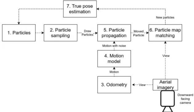
Figure 1: Proposed particle filtering algorithm including visual odometry
2
VISION-BASED PARTICLE FILTER
LOCALIZATION
This paragraph shows the theory behind particle fil-ter localization and algorithms used in particular steps particle filtering. Fig. 1 shows the schema of the pro-posed algorithm. Each step is described in subsections in details.
2.1
Particles
Particle is a hypothesis for the aircraft’s possible posi-tion in map. A number of particles is maintained in the algorithm to evaluate more than one possible location of the aircraft and propagate the possibilities over time. Each particle is assigned an image similarity value on time t
bt=bt−1
Rt+1
2
that is calculated using UAV image similarity value
Rt with the map image on the particle location.
Ini-tial particle density value is assignedb0=1. Particles
are also assigned weight value which is used during sampling. The particle weightwiis calculated by
nor-malizing all probabilitieswi,t= bi,t
∑nj=0bt,j, wherenis the
number of particles,iis single particle index,t is time of current iteration.
2.2
Particle sampling
Sampling is the stage of the Particle Filter when particles are re-sampled according to their weight. Each iteration re-samples particles to find the most plausible UAV location over time. KLD-sampling
technique was selected due it’s to ability to dynamic-ally adjust particle count thus reducing computational costs when it is not necessary. Sampling uses Kueller-Leiblach distance [6] to calculate minimal number of particles that keeps particle probability distribution the same. The technique has shown good results against other sampling techniques on simulated flight data - it provides the same localization accuracy, but dynamic particle count allows to decrease computational times up to 1.7 times [7].
2.3
Odometry
Visual odometry is the process of calculating aircraft (or robot) motion from camera images. In this setup monocular SVO [5] (abbr. Semi-direct Visual Odo-metry) with downward facing camera is used to calcu-late motion. SVO algorithm was selected due to high accuracy compared with other algorithms and real-time execution on embedded is possible due to semi-dense algorithm implementation.
SVO algorithm was selected because of more accurate positioning compared to other algorithms and real-time execution on embedded platforms. SVO algorithm was shown to run 55 frames per second on an embedded flight computer.
2.4
Motion model
Motion model is used for dead-reckoning of the UAV pose from odometry data (visual and movement speed sensors). The UAV pose may be described using six parameters
hx,y,z,θroll,θpitch,θyawiin space relative to the known
locations in 3D environment. Parameter z is equivalent to altitude, which can be measured using sensors (baro-meter, laser) with relatively high precision.
In the case of localization in orthophoto map the alti-tude is only required for image pixel scaling, so it can be ignored during localization. Roll and pitch angles are required for the calculation of camera relative elev-ation angle and image center on the map. Those para-meters can be ignored by using camera gimbal hard-ware in the case if camera is configured to always look downward. The search space thus is narrowed down to pseudo-planar movement using only three parameters (see fig. 2), where aircraft posePt=hx,y,θyawi, where
θyaw is UAV heading angle (UAV platform angle to
North). Figure 2 shows planar movement of the particle with appriori position hx,y,θi and posteriori position
hx0,y0,θ0i. Particle movement is described as
transla-tional movement ˆδtran=δtran+εtran, where
• δˆtranis planar movement with an extra noise
• δtran is measured movement change measured by
sensors (usually odometry)
• εtranis additional random noise value
Rotational movement is described as ˆδrot =δrot+εrot,
equation explanation is analogues to translational movement.
The pose update can be calculated after new sensor data using these equations [12]:
x0=x+α1δˆtrancos(θyaw+α3δˆrot)
y0=y+α2δˆtransin(θyaw+α3δˆrot)
θyaw0 =θyaw+α3δˆrot
, where:
• x0,y0andθyaw0 are posterior UAV location relative to
the orthophoto map
• αn- measurement noise scale coefficients, selected
manually
• δˆtran- translational (movement speed) measurement
with measurement noiseεtran, obtained:
ˆ
δtran=δtran+sample_normal(εtran)
re-sampling. Propagation moves the old re-sampled particles into their current locations according to move-ment that happened since last Particle Filter iteration.
2.6
Particle map matching
Template matching technique is used to match image viewed by the camera and cropped image from map on the particle pose. Matching is done using mono-chrome gray scale images to make the matching faster. The pixel gray scale valueyis calculated using formula from OpenCV library [2]:
yx,y=0.299rx,y+0.587gx,y+0.114bx,y
, whererx,y,gx,y andbx,yare the respective red, green
and blue pixel values on image x and y coordinates. Normalized correlation coefficient (CCOEFF) from OpenCV [2] library was used to calculate image similarity Rt on time t between camera imageT and
cropped map imageI:
Rt= ∑wx=0∑hy=0(T0(x,y)·I0(x,y)) q ∑wx=0∑hy=0T0(x,y)2·∑wx=0∑hy=0I0(x,y)2 , where • T0(x,y) =T(x,y)−∑ w x0=0∑ h y0=0T(x 0 ,y0) w·h • I0(x,y) =I(x,y)−∑ w x0=0∑ h y0=0I(x 0,y0) w·h
• w,hare the image dimensions (width and height).
2.7
UAV Pose Estimation
True location of the UAV is calculated by recursively estimating particle belief density values as described in [12]. Belief is calculated for each particle as conditional probability
bel(Pt) =p(Pt|P0:t−1,m1:t−1,b1:t−1)
, where
• Pt - predicted aircraft pose on timet
• mt - sensor data (may be IMU, barometer, wind
speed and other data used for dead-reckoning) on timet
Figure 3: Correlation coefficient values when matching map with aerial imagery on all heading angles.
• bt - previously described particle probability
value on timet
The belief is a probability on locationPt, conditioned
on all previous sensor data and all particle probability density values. The particle with highest belief is con-sidered to be the true UAV pose for current iteration.
3
EXPERIMENTAL RESULTS
This section describes experimental environment, hard-ware components used for data collection and obtained results
3.1
Experimental setup
A fixed-wing UAV was used to collect aerial imagery and sensor data during 1 km flight. Basler acA640-120uc industrial camera with global shutter was used to collect aerial imagery alongside with other sensor data provided from UAV flight controller. Images was corded in 640x480 resolution at 90 FPS. Data was re-corded using MPEG2-TS video format and sensor data was recorded as meta-data alongside the video stream. The video playback allows data to be read with the same timing as it was recorded on UAV. Map used for matching was downloaded from Google Maps [10] us-ing highest available zoom level. Initial particle count for the particle filter was set to 500.
3.2
UAV Heading impact on correlation
coefficient
This section investigates magnetometer error impact on correlation coefficient since it was noticed during loc-alization experiment. Typical magnetometers used in UAV’s may contain noise in measuring heading direc-tion. Fig. 3 presents correlation coefficient values for 6 images captured during real flight and matched with according orthophoto map images. Table 1 contains av-erage similarity change values versus heading change. Data from table 1 suggests that +/- 2 degrees of heading
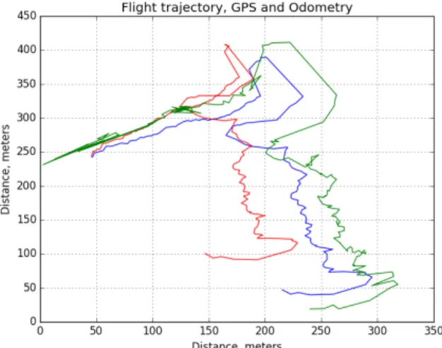
Figure 4: Flight trajectory reconstruction using odo-metry (red), particle filter (green) and conventional GPS sensor (blue).
Figure 5: Particle filter localization and visual odo-metry absolute errors.
angle error can be ignored, because it affects correlation coefficient only up to 10% on average.
Table 1: Heading change impact on similarity coeffi-cient
Average similarity Heading change,◦ change, %
+10 67.78 +5 34.59 +2 9.38 -2 10.15 -5 35.49 -10 62.08
3.3
Localization accuracy
In this section we will evaluate localization accuracy compared with conventional GPS positioning system
shows that proposed algorithm adds a lot less errors during long time flights. Additional experiments are required to validate whether errors won’t add up after longer flights. Particle filter localization was able to keep error values in around 50 meter range. After the 1 kilometer flight the final error was reduced by a factor of 2 compared to localization from visual odometry only. Proposed algorithm error trend-line slope is reduced by a factor of 11 times compared with visual odometry.
4
CONCLUSIONS AND FUTURE
WORK
This paper analyses an application of particle filter for UAV localization in previously known orthophoto map using images from downward facing camera on the UAV platform. The obtained results concludes:
• Flight heading error +/- 2 degrees causes correlation coefficients errors in up to 10% range. Particle filter execution was done with +/- 5 degree uncertainty in UAV heading.
• Experiment on real flight data shows that particle fil-ter is able to reduce the slope of accumulating errors with a factor of 11 times compared to visual odo-metry.
• At the end of experimental flight, particle filter loc-alization allowed to improve position precision by a factor of 2 compared with position from odometry data only.
Future work in the field of this paper would include additional experiments comparing proposed algorithm with geo-referencing based localization to benchmark localization accuracy. An alternative image similarity coefficient based on deep learning can be proposed in replacement of correlation coefficient to improve local-ization accuracy of the algorithm.
5
ACKNOWLEDGEMENT
The results of this research was obtained during devel-opment of project "Develdevel-opment of hybrid unmanned air vehicle for homeland defense purposes (No. KAM-01-08)" coordinated by Vilnius University
[3] Fernando Caballero et al. ‘Vision-based odo-metry and SLAM for medium and high altitude flying UAVs’. In: Journal of Intelligent and Robotic Systems54.1-3 (2009), pp. 137–161. [4] Frank Dellaert, Sebastian Thrun, and Charles E
Thorpe.Mosaicing a large number of widely dis-persed, noisy, and distorted images: A bayesian approach. Carnegie Mellon University, The Ro-botics Institute, 1999.
[5] Christian Forster, Matia Pizzoli, and Davide Scaramuzza. ‘SVO: Fast semi-direct monocular visual odometry’. In: Robotics and Automation (ICRA), 2014 IEEE International Conference on. IEEE. 2014, pp. 15–22.
[6] Dieter Fox. ‘KLD-sampling: Adaptive particle filters’. In:Advances in neural information pro-cessing systems. 2001, pp. 713–720.
[7] R Jurevicius, V Marcinkevicius, and V Taujanskas. ‘Comparison of image similarity functions and sampling algorithms in vision-based particle filter for UAV localization’. In: (2016).
[8] Andrew J Kerns et al. ‘Unmanned aircraft cap-ture and control via GPS spoofing’. In:Journal of Field Robotics31.4 (2014), pp. 617–636. [9] Georg Klein and David Murray. ‘Parallel
track-ing and mapptrack-ing for small AR workspaces’. In: Mixed and Augmented Reality, 2007. IS-MAR 2007. 6th IEEE and ACM International Symposium on. IEEE. 2007, pp. 225–234. [10] Gabriel Svennerberg. Beginning Google Maps
API 3. Apress, 2010.
[11] Sebastian Thrun. ‘Particle filters in robotics’. In:Proceedings of the Eighteenth conference on Uncertainty in artificial intelligence. Morgan Kaufmann Publishers Inc. 2002, pp. 511–518. [12] Sebastian Thrun, Wolfram Burgard, and Dieter
Fox.Probabilistic robotics. 2005.
[13] Sebastian Thrun et al. ‘Robust Monte Carlo loc-alization for mobile robots’. In:Artificial intelli-gence128.1 (2001), pp. 99–141.