Simulating Wind Over Terrain: How to Build an OpenFOAM Case
from GRASS GIS Digital Elevation Models
Eric Hardin [email protected]
April 26, 2013
Abstract
This document describes the process for generating an OpenFOAM case from digital elevation model (DEM) data in GRASS GIS format for the purpose of simulating the wind field over complex terrains. Specifically, the steps are shown to adapt thecavitytutorial case to simulate the wind field over Jockey’s Ridge Sand Dune. Additionally, the wind-borne surface shear stress is computed and imported back into GRASS GIS.
Keywords. OpenFOAM, GRASS GIS, wind modeling, complex terrain, surface shear stress
1
Introduction
This document covers the basics of how to build an OpenFOAM case from GRASS DEM data for the purpose of simulating the wind field over a complex terrain. In this document, thecavity tuto-rial case (OpenFOAM/OpenFOAM-1.7.x/tutorials/incompressible/icoFoam/cavity; ver. 1.7.x) is adapted to simulate wind over Jockey’s Ridge Sand Dune (DEM data in Jockey’s Ridge data set V 0.1). The cavity tutorial is used here for simplicity because the icoFoam solver requires relatively few case files. Other tutorial cases can be adapted with a similar workflow (e.g, the pitzDaily case, which uses the steady-state turbulence solver, simpleFoam).
This document is organized as follows: Section 2 covers manipulation of GRASS DEM data for OpenFOAM mesh generation; Section 3 describes editing boundary conditions; Section 4 briefly describes execution of a solver for computation of the wind field; Section 5 describes computation of the surface shear stress (required for sand flux studies), as well as importing the shear stress results back into GRASS; and Section 6 is a brief summary of the OpenFoam module execution. The appendix includes some miscellaneous notes, a Python script that converts GRASS DEMs to stereolithography (STL) format, and the case files that result from the workflow described here. Caveat: I hope this document can be helpful for someone trying to incorporate terrain into OpenFOAM simulations. The workflow outlined here is only meant to help produce a minimal working OpenFOAM case, which incorporates complex terrain from GRASS DEMs. The case will likely produce poor results because much of the sophistication required to accurately model wind has been left out for succinctness. But once the case is indeed producing results, then additional complexity beyond the scope of this document can be incorporated.
2
Generate a New OpenFOAM Mesh from DEM Data
To begin, copy and rename thecavitytutorial case
cd OpenFOAM/OpenFOAM-1.7.x/tutorials/incompressible/icoFoam cp -r cavity JR
cd JR
OpenFOAM mesh generation occurs in two steps: (1) a background mesh is generated, and (2) the mesh is refined to fit a geometry (e.g., an air foil or in our case, the terrain surface).
• BlockMeshgenerates the background mesh according toconstant/polyMesh/blockMeshDict
• SnappyHexMeshrefines the mesh according to system/snappyHexMeshDict
• a .stl file inconstant/triSurface defines the geometry
The cavity tutorial does not use snappyHexMesh, so the constant/triSurfaces directory,
thesnappyHexMeshDict, and also decomposeParDict need to be included in the case. These can
be copied from another tutorial.
mkdir constant/triSurface
cp ../../simpleFoam/motorBike/system/snappyHexMeshDict system/ cp ../../simpleFoam/motorBike/system/decomposeParDict system/
2.1 Generate STL Geometry
First, we generate the STL geometry by converting a GRASS raster DEM to STL format. STL format is similar to a TIN, except it defines the shell of a volume with a set of interlocking triangular facets. STL files begin with the name of the geometry
solid solid_name
and end with
endsolid solid_name
where solid_name is user defined. Between these lines is a list of triangular facets. A facet is defined with facet normal ni nj nk outer loop vertex v1x v1y v1z vertex v2x v2y v2z vertex v3x v3y v3z endloop endfacet
whereni nj nk are the components of a normalized surface-normal vector, andv1x v1y v1z
are the coordinates of the first vertex in the triangular face.
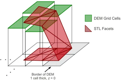
Facets can be generated by connecting the centers of four adjacent raster cells in the DEM to make two facets (Figure 1). Additionally, the STL geometry needs to enclose a volume, which
DEM Grid Cells STL Facets Border of DEM 1 cell thick, z = 0
. . .
. .
.
Figure 1: Converting a raster DEM to STL format by connecting raster grid cell centers to make facets. STL encloses a volume, and so there need to be facets along the terrain surface and also at a base elevation.
means that the DEM needs a bottom. So for each facet, I generate a flat facet directly below it at a base elevation (e.g., same (x, y) but z = 0). To connect the DEM to the base so that the STL geometry completely encloses a volume, I make a border around the DEM that is one raster cell thick with an elevation equal to the base elevation. The Python script that converts DEMs to STL format is included in Appendix B. Also, OpenFOAM doesn’t seem to like the large coordinate values that are typical for a state plane coordinate system, so the script translates coordinates back to the origin.
For the purpose of this example, let’s zoom to a smaller region to keep the OpenFOAM case file from getting too large
g.region n=250308 s=249838 w=913389 e=914037 res=1
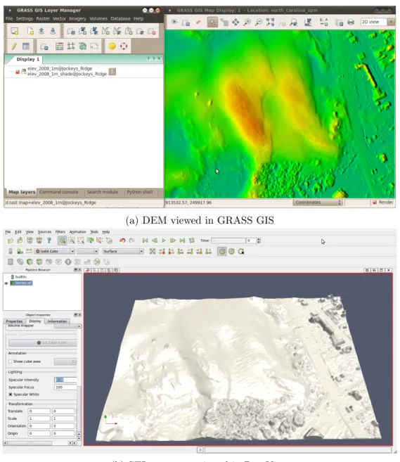
Now, we can run the script to convert the DEM to an STL file – making sure the resulting .stl file is in constant/triSurface. For convenience, I call the Python interpreter from inside the GRASS terminal, and then, copy-and-paste the script text into the interpreter. The DEM (viewed in GRASS) is shown in Figure 2a and the converted STL file (viewed in ParaView) is shown in Figure 2b.
2.2 Edit blockMeshDict
Once the STL geometry has been generated, a new background mesh needs to be generated, which requires editing theblockMeshDict. The GRASS region was 470 m in the N-S direction and 648 m in the E-W direction with 1 m resolution, so change the location of the eight vertices that define the computational domain and the mesh grading (Appendix C.3). Also, the cavitytutorial case is 2D. To change it to 3D, change theemptytype patches towalltype patches; I called one of the patches inlet and the other outlet because I was intending to set up a horizontal wind. Once
blockMeshDictis edited, generate the background mesh by running
(a) DEM viewed in GRASS GIS
(b) STL geometry viewed in ParaView
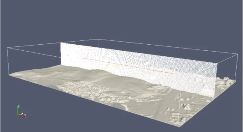
Figure 3: STL terrain surface geometry and cross-section of OpenFOAM mesh, viewed in ParaView.
2.3 Edit snappyHexMeshDict
Once the background mesh is generated, change thesnappyHexMeshDictin the following ways:
• comment out the refinementBox on lines 37-42 and 138-142
• replacemotorBike withterrain (i.e., the name of our geometry) on lines 31, 34, 112
• remove layers definition from lines 189 to 463 and replace with
layers { terrain.* { nSurfaceLayers 4; } }
• change locationInMesh in line 154 to be a location within the computational domain and above the DEM surface, e.g., locationInMesh (10 10 90);
Now, complete the mesh generation by running
snappyHexMesh -overwrite
3
Change Boundary Conditions
Boundary conditions are stored in the 0 directory: U is the fluid velocity and p is the pressure. An initial condition needs to be specified for each boundary, i.e., each type of wall patch. In
BlockMeshDict, wall patches are defined (e.g., movingWall, fixedWalls, inlet, and outlet). snappy-HexMesh defines an additional patch, which is called geometry name wheregeometry is the name of the .stl file, andname is the name of the solid in the first line of the stl file, e.g.,solid terrain.
The boundary conditions are as follows: forU: • outlet gets outlet { type zeroGradient; }
• and everything else gets
wall_name {
type fixedValue;
value uniform (vx vy vz);
}
wherewall name is the user-defined name andvx vy vzare numerical values. forp: • outlet gets outlet { type fixedValue; value uniform 0; }
• and everything else gets
wall_name {
type zeroGradient;
}
wherewall name is the user-defined name. More sophisticated boundary conditions are avail-able as well.
4
Compute Fluid Flow
Once the mesh is generated and the boundary conditions are specified, the non-turbulent, incom-pressible fluid flow is computed by executing
icoFoam
Simulation details (e.g,. time step and write interval) are specified in system/controlDict. In this file the solver is also specified.
5
Compute Surface Shear Stress
Once the fluid flow is computed, the shear stress can be computed by running
wallShearStress -latestTime
The surface shear stress along terrain can be sampled (for easier processing) by generating the
system/sampleDictfile (included in Appendix C.7) and running:
sample
The resulting surface shear stress will be written to surfaces/"latestTime"/wallShearStress_ wall.rawwhere"latestTime"is the latest time step to have output data written. ThewallShearStress_ wall.rawfile contains a two-line header followed by six-column space delimited data in which the fields are x,y,z,τx,τy, and τz, whereτ is the surface shear stress. The data can be imported into
GRASS using
v.in.ascii input=wallShearStress_wall.raw output=wallShearStress_wall fs=’ ’ \
skip=2 columns=’x double precision, y double precision, z double precision, \
tau_x double precision, tau_y double precision, tau_z double precision’
Raster maps representing the surface shear stress can be interpolated by executing
v.surf.bspline input=wallShearStress_wall raster=tau_x column=tau_x v.surf.bspline input=wallShearStress_wall raster=tau_y column=tau_y r.mapcalc expression=’tau=sqrt(tau_x^2+tau_y^2)’
6
Summary of Module Execution
blockMesh
snappyHexMesh -overwrite icoFoam >& log
wallShearStress -latestTime sample
References
[1] Eric Hardin. (2013). A Transient Landscape: Geospatial Analysis and Numerical Modeling of Coastal Geomorphology in the Outer Banks, North Carolina. (Doctoral dissertation). http:
A
Miscilaneous Notes
• If you get:
--> FOAM FATAL IO ERROR: cannot find file
file: /home/eric/OpenFOAM/eric-2.1.0/run/tutorials/incompressible/icoFoam/JR\
/0.5/p at line 0.
then this is because snappyHexMesh was not executed with -overwrite. Rerun snappy-HexMesh with-overwrite– or – copy the contents oflastTimeStep/polyMeshtoconstant/ polyMesh.
• If you alter blockMeshDict and rerun snappyHexMesh, you will get an error. In this case, you need to delete the contents of constant/polyMeshexcept forblockMeshDictand rerun snappyHexMesh.
• If you get
--> FOAM FATAL IO ERROR:
Unable to set reference cell for field p Please supply either pRefCell or pRefPoint
when running simpleFoam, add lines
pRefPoint (x y z); pRefValue 0;
intoSimple{} dictionary insystem/fvSolution wherex y z is a location in the
computa-tional domain and above the terrain surface.
• if you get a continuity error, try running
checkMesh
The mesh may have a problem.
• if you try to view the mesh in ParaView and you can only see the terrain, then check to make sure ref point in snappyHexMeshDictis above the terrain surface.
• If you get an error running paraFoam, then try running
foamToVTK paraview
If this gives an error, then
cd /0 rm cell
• To incorporate surface roughness, in0/nutreplacenutWallFunctionwithnutRoughWallFunction terrain_terrain { //type nutWallFunction; type nutRoughWallFunction; Ks uniform 0.02; Cs uniform 0.5; value uniform 0; }
• The solver potentialFoam solves for the potential flow. The results of potentialFoam can be used as the initial condition for other solvers, e.g., simpleFoam. This can improve stability and time to convergence. To use potentialFoam to generate improved initial conditions for a simpleFoam case
1. edit system/controlDictby changingsimpleFoamtopotentialFoam
2. edit system/fvSchemes by changinglaplacian((1|A(U)),p) tolaplacian(1,p)
3. run potentialFoam 4. revert changes 5. run simpleFoam
B
Convert DEM to STL script
1 import grass.script as grass
2 import tempfile
3 from numpy import array,cross,sqrt
4 5 dem_name = ’elev_2008_1m’ 6 solid_name = ’terrain’ 7 foutname = ’constant/triSurface/terrain.stl’ 8 9 def make_facet_str( n, v1, v2, v3 ):
10 facet_str = ’facet normal ’ + ’ ’.join( map(str,n) ) + ’\n’
11 facet_str += ’ outer loop\n’
12 facet_str += ’ vertex ’ + ’ ’.join( map(str,v1) ) + ’\n’
13 facet_str += ’ vertex ’ + ’ ’.join( map(str,v2) ) + ’\n’
14 facet_str += ’ vertex ’ + ’ ’.join( map(str,v3) ) + ’\n’
15 facet_str += ’ endloop\n’
16 facet_str += ’endfacet\n’
17 return facet_str
18
19 # make a dem but with a border of minimum elevation
20 stats = grass.parse_command(’r.univar’, flags=’g’, map=dem_name)
21 base_elev = float(stats[’min’]) - 0.1 # base is 0.1m below min elev but could be
anything
22 reg = grass.region()
23 grass.run_command(’r.mapcalc’, expression=’temp=’+dem_name, overwrite=True)
24 # extend region by one cell for border
25 n_new = reg[’n’]+reg[’nsres’]
26 s_new = reg[’s’]-reg[’nsres’]
27 e_new = reg[’e’]+reg[’ewres’]
28 w_new = reg[’w’]-reg[’ewres’]
29 grass.run_command(’g.region’, n=n_new, s=s_new, e=e_new, w=w_new)
30 grass.run_command(’r.mapcalc’, expression=’temp2=if(isnull(temp),’+str(base_elev)
+’,temp)’, overwrite=True) 31
32 # read raster data
33 elev = grass.read_command(’r.out.ascii’, input=’temp2’, output=’-’)
34 elev = elev.strip(’\n’).split(’\n’)[6:]
35 elev = [ map(float,line.split()) for line in elev ]
36 # transpose and reverse to make [0,0] the SW corner
37 elev.reverse()
38 elev = map(list, zip(*elev))
39
40 # construct text for STL file
42 for i in range(len(elev)-1): 43 for j in range(len(elev[0])-1): 44 x = (i-1)*reg[’ewres’]; y = (j-1)*reg[’nsres’] 45 v1 = [ x, y, elev[i][j] ] 46 x = i*reg[’ewres’]; y = (j-1)*reg[’nsres’] 47 v2 = [ x, y, elev[i+1][j] ] 48 x = (i-1)*reg[’ewres’]; y = j*reg[’nsres’] 49 v3 = [ x, y, elev[i][j+1] ] 50 x = i*reg[’ewres’]; y = j*reg[’nsres’] 51 v4 = [ x, y, elev[i+1][j+1] ] 52 # dem facet 1
53 n = cross( array(v1)-array(v2), array(v1)-array(v3) )
54 n = n / sqrt( sum( n**2 ) )
55 stl_str += make_facet_str( n, v1, v2, v3 )
56 # dem facet 2
57 n = cross( array(v2)-array(v3), array(v2)-array(v4) )
58 n = n / sqrt( sum( n**2 ) ) 59 stl_str += make_facet_str( n, v2, v3, v4 ) 60 # base facets 61 v1[-1] = base_elev 62 v2[-1] = base_elev 63 v3[-1] = base_elev 64 v4[-1] = base_elev 65 n = [0.0,0.0,-1.0] 66 stl_str += make_facet_str( n, v1, v2, v3 ) 67 stl_str += make_facet_str( n, v2, v3, v4 ) 68 69 stl_str += ’endsolid ’ + solid_name + ’\n’ 70 71 fout = open(foutname, ’w’) 72 fout.write( stl_str ) 73 fout.close()
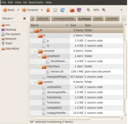
Figure 4: OpenFOAM directory tree and case files.
C
Case Directory and Case files
C.1 0/p
/*---*- C++ -*---*\
| ========= | |
| \\ / F ield | OpenFOAM: The Open Source CFD Toolbox |
| \\ / O peration | Version: 1.7.1 | | \\ / A nd | Web: www.OpenFOAM.com | | \\/ M anipulation | | \*---*/ FoamFile { version 2.0; format ascii; class volScalarField; object p; } // * * * * * * * * * * * * * * * * * * * * * * * * * * * * * * * * * * * * * // dimensions [0 2 -2 0 0 0 0]; internalField uniform 0; boundaryField { movingWall { type zeroGradient; } fixedWalls { type zeroGradient; } inlet { type zeroGradient; } outlet { type fixedValue; value uniform 0; } terrain_terrain
{
type zeroGradient;
} }
C.2 0/U
/*---*- C++ -*---*\
| ========= | |
| \\ / F ield | OpenFOAM: The Open Source CFD Toolbox |
| \\ / O peration | Version: 1.7.1 | | \\ / A nd | Web: www.OpenFOAM.com | | \\/ M anipulation | | \*---*/ FoamFile { version 2.0; format ascii; class volVectorField; object U; } // * * * * * * * * * * * * * * * * * * * * * * * * * * * * * * * * * * * * * // dimensions [0 1 -1 0 0 0 0]; internalField uniform (0 -10 0); boundaryField { movingWall { type fixedValue; value uniform (0 -10 0); } fixedWalls { type fixedValue; value uniform (0 0 0); } inlet { type fixedValue; value uniform (0 -10 0); } outlet { type zeroGradient; }
terrain_terrain { type fixedValue; value uniform (0 0 0); } } // ************************************************************************* //
C.3 constant/polyMesh/blockMeshDict
/*---*- C++ -*---*\
| ========= | |
| \\ / F ield | OpenFOAM: The Open Source CFD Toolbox |
| \\ / O peration | Version: 1.7.1 | | \\ / A nd | Web: www.OpenFOAM.com | | \\/ M anipulation | | \*---*/ FoamFile { version 2.0; format ascii; class dictionary; object blockMeshDict; } // * * * * * * * * * * * * * * * * * * * * * * * * * * * * * * * * * * * * * // convertToMeters 1; vertices ( (0 0 0) (648 0 0) (648 470 0) (0 470 0) (0 0 100) (648 0 100) (648 470 100) (0 470 100) ); blocks ( hex (0 1 2 3 4 5 6 7) (324 235 50) simpleGrading (1 1 1) ); edges ( ); patches ( wall movingWall ( (3 7 6 2)
) wall fixedWalls ( (0 4 7 3) (2 6 5 1) (1 5 4 0) ) wall inlet ( (4 5 6 7) ) wall outlet ( (0 3 2 1) ) ); mergePatchPairs ( ); // ************************************************************************* //
C.4 system/controlDict
/*---*- C++ -*---*\
| ========= | |
| \\ / F ield | OpenFOAM: The Open Source CFD Toolbox |
| \\ / O peration | Version: 1.7.1 | | \\ / A nd | Web: www.OpenFOAM.com | | \\/ M anipulation | | \*---*/ FoamFile { version 2.0; format ascii; class dictionary; location "system"; object controlDict; } // * * * * * * * * * * * * * * * * * * * * * * * * * * * * * * * * * * * * * // application icoFoam; startFrom startTime; startTime 0; stopAt endTime; endTime 0.5; deltaT 0.05; writeControl timeStep; writeInterval 5; purgeWrite 0; writeFormat ascii; writePrecision 6; writeCompression uncompressed; timeFormat general; timePrecision 6;
runTimeModifiable yes;
C.5 system/fvSchemes
/*---*- C++ -*---*\
| ========= | |
| \\ / F ield | OpenFOAM: The Open Source CFD Toolbox |
| \\ / O peration | Version: 1.7.1 | | \\ / A nd | Web: www.OpenFOAM.com | | \\/ M anipulation | | \*---*/ FoamFile { version 2.0; format ascii; class dictionary; location "system"; object fvSchemes; } // * * * * * * * * * * * * * * * * * * * * * * * * * * * * * * * * * * * * * // ddtSchemes { default Euler; } gradSchemes {
default Gauss linear;
grad(p) Gauss linear;
}
divSchemes {
default none;
div(phi,U) Gauss linear;
}
laplacianSchemes {
default none;
laplacian(nu,U) Gauss linear corrected;
laplacian((1|A(U)),p) Gauss linear corrected; }
interpolationSchemes {
interpolate(HbyA) linear; } snGradSchemes { default corrected; } fluxRequired { default no; p ; } // ************************************************************************* //
C.6 system/fvSolution
/*---*- C++ -*---*\
| ========= | |
| \\ / F ield | OpenFOAM: The Open Source CFD Toolbox |
| \\ / O peration | Version: 1.7.1 | | \\ / A nd | Web: www.OpenFOAM.com | | \\/ M anipulation | | \*---*/ FoamFile { version 2.0; format ascii; class dictionary; location "system"; object fvSolution; } // * * * * * * * * * * * * * * * * * * * * * * * * * * * * * * * * * * * * * // solvers { p { solver PCG; preconditioner DIC; tolerance 1e-06; relTol 0; } U { solver PBiCG; preconditioner DILU; tolerance 1e-05; relTol 0; } } PISO { nCorrectors 2; nNonOrthogonalCorrectors 0; pRefCell 0; pRefValue 0; } // ************************************************************************* //
C.7 system/sampleDict
/*---*- C++ -*---*\
| ========= | |
| \\ / F ield | OpenFOAM: The Open Source CFD Toolbox |
| \\ / O peration | Version: 2.1.0 | | \\ / A nd | Web: www.OpenFOAM.org | | \\/ M anipulation | | \*---*/ FoamFile { version 2.0; format ascii; class dictionary; location system; object sampleDict; } // * * * * * * * * * * * * * * * * * * * * * * * * * * * * * * * * * * * * // setFormat xmgr; surfaceFormat raw; interpolationScheme cellPoint; fields ( wallShearStress ); sets ( ); surfaces ( wall { type patch; patchName terrain_terrain; } ); // *********************************************************************** //
C.8 system/snappyHexMeshDict
/*---*- C++ -*---*\
| ========= | |
| \\ / F ield | OpenFOAM: The Open Source CFD Toolbox |
| \\ / O peration | Version: 1.7.1 | | \\ / A nd | Web: www.OpenFOAM.com | | \\/ M anipulation | | \*---*/ FoamFile { version 2.0; format ascii; class dictionary; object snappyHexMeshDict; } // * * * * * * * * * * * * * * * * * * * * * * * * * * * * * * * * * * * * * // // Which of the steps to run
castellatedMesh true;
snap true;
addLayers true;
// Geometry. Definition of all surfaces. All surfaces are of class // searchableSurface.
// Surfaces are used
// - to specify refinement for any mesh cell intersecting it // - to specify refinement for any mesh cell inside/outside/near // - to ’snap’ the mesh boundary to the surface
geometry { terrain.stl { type triSurfaceMesh; name terrain; } /*refinementBox { type searchableBox; min (-1.0 -0.7 0.0); max ( 8.0 0.7 2.5); }*/ };
// Settings for the castellatedMesh generation. castellatedMeshControls
{
// Refinement parameters // ~~~~~~~~~~~~~~~~~~~~~
// If local number of cells is >= maxLocalCells on any processor // switches from from refinement followed by balancing
// (current method) to (weighted) balancing before refinement. maxLocalCells 1000000;
// Overall cell limit (approximately). Refinement will stop immediately // upon reaching this number so a refinement level might not complete. // Note that this is the number of cells before removing the part which // is not ’visible’ from the keepPoint. The final number of cells might // actually be a lot less.
maxGlobalCells 2000000;
// The surface refinement loop might spend lots of iterations refining just a // few cells. This setting will cause refinement to stop if <= minimumRefine // are selected for refinement. Note: it will at least do one iteration // (unless the number of cells to refine is 0)
minRefinementCells 10;
// Allow a certain level of imbalance during refining // (since balancing is quite expensive)
// Expressed as fraction of perfect balance (= overall number of cells / // nProcs). 0=balance always.
maxLoadUnbalance 0.10;
// Number of buffer layers between different levels.
// 1 means normal 2:1 refinement restriction, larger means slower // refinement.
nCellsBetweenLevels 3;
// Explicit feature edge refinement // ~~~~~~~~~~~~~~~~~~~~~~~~~~~~~~~~
// This is a featureEdgeMesh, read from constant/triSurface for now. features ( //{ // file "someLine.eMesh"; // level 2; //} );
// Surface based refinement // ~~~~~~~~~~~~~~~~~~~~~~~~
// Specifies two levels for every surface. The first is the minimum level, // every cell intersecting a surface gets refined up to the minimum level. // The second level is the maximum level. Cells that ’see’ multiple
// intersections where the intersections make an
// angle > resolveFeatureAngle get refined up to the maximum level. refinementSurfaces
{
terrain {
// Surface-wise min and max refinement level level (5 6);
} }
// Resolve sharp angles resolveFeatureAngle 30;
// Region-wise refinement // ~~~~~~~~~~~~~~~~~~~~~~
// Specifies refinement level for cells in relation to a surface. One of // three modes
// - distance. ’levels’ specifies per distance to the surface the
// wanted refinement level. The distances need to be specified in
// descending order.
// - inside. ’levels’ is only one entry and only the level is used. All
// cells inside the surface get refined up to the level. The surface
// needs to be closed for this to be possible.
refinementRegions { //refinementBox //{ // mode inside; // levels ((1E15 4)); //} } // Mesh selection // ~~~~~~~~~~~~~~
// After refinement patches get added for all refinementSurfaces and // all cells intersecting the surfaces get put into these patches. The // section reachable from the locationInMesh is kept.
// NOTE: This point should never be on a face, always inside a cell, even // after refinement.
//locationInMesh (3 3 0.43); locationInMesh (10 10 90); }
// Settings for the snapping. snapControls
{
//- Number of patch smoothing iterations before finding correspondence
// to surface
nSmoothPatch 3;
//- Relative distance for points to be attracted by surface feature point
// or edge. True distance is this factor times local
// maximum edge length.
tolerance 4.0;
//- Number of mesh displacement relaxation iterations. nSolveIter 30;
//- Maximum number of snapping relaxation iterations. Should stop
// before upon reaching a correct mesh.
nRelaxIter 5; }
// Settings for the layer addition. addLayersControls
{
// Are the thickness parameters below relative to the undistorted
// size of the refined cell outside layer (true) or absolute sizes (false). relativeSizes true;
// Per final patch (so not geometry!) the layer information layers { //"(outlet|terrain).*" terrain.* { nSurfaceLayers 4; } }
// Expansion factor for layer mesh expansionRatio 1.0;
//- Wanted thickness of final added cell layer. If multiple layers
// is the thickness of the layer furthest away from the wall.
// See relativeSizes parameter.
finalLayerThickness 0.3;
//- Minimum thickness of cell layer. If for any reason layer
// cannot be above minThickness do not add layer.
// Relative to undistorted size of cell outside layer.
minThickness 0.1;
//- If points get not extruded do nGrow layers of connected faces that are
// also not grown. This helps convergence of the layer addition process
// close to features.
nGrow 1;
// Advanced settings
//- When not to extrude surface. 0 is flat surface, 90 is when two faces
// make straight angle.
featureAngle 30;
// before upon reaching a correct mesh. nRelaxIter 3;
// Number of smoothing iterations of surface normals nSmoothSurfaceNormals 1;
// Number of smoothing iterations of interior mesh movement direction nSmoothNormals 3;
// Smooth layer thickness over surface patches nSmoothThickness 10;
// Stop layer growth on highly warped cells maxFaceThicknessRatio 0.5;
// Reduce layer growth where ratio thickness to medial // distance is large
maxThicknessToMedialRatio 0.3;
// Angle used to pick up medial axis points minMedianAxisAngle 130;
// Create buffer region for new layer terminations nBufferCellsNoExtrude 0;
// Overall max number of layer addition iterations nLayerIter 50;
}
// Generic mesh quality settings. At any undoable phase these determine // where to undo.
meshQualityControls {
//- Maximum non-orthogonality allowed. Set to 180 to disable. maxNonOrtho 65;
//- Max skewness allowed. Set to <0 to disable. maxBoundarySkewness 20;
maxInternalSkewness 4;
//- Max concaveness allowed. Is angle (in degrees) below which concavity
// is allowed. 0 is straight face, <0 would be convex face.
maxConcave 80;
//- Minimum projected area v.s. actual area. Set to -1 to disable. minFlatness 0.5;
//- Minimum pyramid volume. Is absolute volume of cell pyramid.
// Set to a sensible fraction of the smallest cell volume expected.
// Set to very negative number (e.g. -1E30) to disable.
minVol 1e-13;
//- Minimum face area. Set to <0 to disable. minArea -1;
//- Minimum face twist. Set to <-1 to disable. dot product of face normal //- and face centre triangles normal
minTwist 0.02;
//- minimum normalised cell determinant
//- 1 = hex, <= 0 = folded or flattened illegal cell minDeterminant 0.001;
//- minFaceWeight (0 -> 0.5) minFaceWeight 0.02;
//- minVolRatio (0 -> 1) minVolRatio 0.01;
//must be >0 for Fluent compatibility minTriangleTwist -1;
// Advanced
//- Number of error distribution iterations nSmoothScale 4;
//- amount to scale back displacement at error points errorReduction 0.75;
}
// Advanced
// Flags for optional output // 0 : only write final meshes // 1 : write intermediate meshes
// 2 : write volScalarField with cellLevel for postprocessing // 4 : write current intersections as .obj files
debug 0;
// Merge tolerance. Is fraction of overall bounding box of initial mesh. // Note: the write tolerance needs to be higher than this.
mergeTolerance 1E-6;