Procedia Computer Science 46 ( 2015 ) 812 – 819
1877-0509 © 2015 The Authors. Published by Elsevier B.V. This is an open access article under the CC BY-NC-ND license (http://creativecommons.org/licenses/by-nc-nd/4.0/).
Peer-review under responsibility of organizing committee of the International Conference on Information and Communication Technologies (ICICT 2014) doi: 10.1016/j.procs.2015.02.150
ScienceDirect
International Conference on Information and Communication Technologies (ICICT 2014)
A Unified Software Framework for Automatic Precise
Georeferencing of Large Remote Sensing Image Archives
Indranil Misra
*S Manthira Moorthi, Debajyoti Dhar and R.Ramakrishnan
Space Applications Centre (ISRO)*
Abstract
, Ahmedabad-380015, Gujarat, India
Though georeferencing satellite images is a solved industry problem long back, every satellite sensor data is unique to process due to its proprietary information and expected geometric accuracies usually demands use of reference data. Industry is moving towards unifying frameworks, sensor models where the users have to just plug-in details. The growing archive is inevitable and therefore (re) processing requirements have to handle huge image archives with state of art georeferencing standards automatically. Use of reference data is necessary to georeference the data sets to better accuracies beyond systematic corrections. This paper presents an approach for such tedious task of automatically reliably georeference huge image archives involving reference image/control points use in georeferencing Indian Remote Sensing satellite images.
© 2014 The Authors. Published by Elsevier B.V.
Peer-review under responsibility of organizing committee of the International Conference on Information and Communication Technologies (ICICT 2014).
Keywords:Geometric Processing,remote sensing, satellite images, image registration, georeferencing, software framework.
1. Introduction
Remote Sensing Images is always being used in geospatial framework for study of various geological, physiological and other scientific details of our planet. The geometric correction of satellite images is one of the key issues in multi sensor data integration and considered to be major processing step for further value added processing
*Corresponding Author: Tel. +91 79 26914194 Email : [email protected]
© 2015 The Authors. Published by Elsevier B.V. This is an open access article under the CC BY-NC-ND license (http://creativecommons.org/licenses/by-nc-nd/4.0/).
Peer-review under responsibility of organizing committee of the International Conference on Information and Communication Technologies (ICICT 2014)
of satellite images such as image fusion, change detection, map updation and integration of data in the geospatial software pipelines1.
Although optical satellite data of high geometric resolution captured from Indian remote sensing (IRS) platforms can be geo corrected to absolute geometric accuracies of 5 m to few hundred meters depending on the satellite mission. But still there is a need to improve the geometric accuracy of images by using automatic precise georeferencing techniques. The manual method of Ground Control Point (GCP) selection and measurement is a time consuming and tedious job to improve the accuracy. So a methodology has been developed and an automatic software processing chain is implemented using a unified software framework. The framework uses global reference image database to update the input remote sensing image archives for better geometric accuracy.
2. Steps in Precise Georeferencing
Precise Georeferencing requires executions of multiple processing steps to meet the quality of the data products. Digital Image Processing techniques are involved at various stages for the processing of the data. The major steps involved in precise georeferencing are:
2.1. Geometric Transformation
The geometric distortion in remote sensing images requires 2D/3D rigorous physical model. The geometric correction using physical model represent the true viewing geometry incorporating platform, sensor, earth and sometimes map projection related parameters. The mathematical function of the 3D physical model using well known co linearity condition and equations for optical images is as follows:
x = (െf)ౣభభ(షబ)శౣభమ(ౕషౕబ)శౣభయ(ౖషౖబ)
ౣయభ(షబ)శౣయమ(ౕషౕబ)శౣయయ(ౖషౖబ) (1)
y = (െf)ౣమభ(షబ)శౣమమ(ౕషౕబ)శౣమయ(ౖషౖబ)
ౣయభ(షబ)శౣయమ(ౕషౕబ)శౣయయ(ౖషౖబ) (2) where: (x,y) are the image coordinates;
(X,Y,Z) are the map coordinates;
(X0,Y0,Z0) are the projection centre coordinates; f is the focal length of the imaging sensor;
mij are the 9 elements of the orthogonal 3-rotation matrix.
But due to altitude variation with sensor focal length, platform attitude variation which includes roll, pitch and yaw, platform velocity variation, topography of the earth can change the pixel spacing in the system level georeferenced product 1. Also in the multi sensor data taken as input and reference for precise georeferencing have different spatial resolution and generally stored in different projection system. So it is needed to perform geometric transformation that bring the input and reference datasets into same projection system and all images are need to resampled to same pixel size using standard resampling technique 1,3.
2.2. Reference Image Generation
For further corrections, the input image becomes the geo-corrected at system level accuracy and stored as Geo Tagged Image File Format (Geotiff)2. The geometric corners of input image can be fetched from the Geotiff data and a polygon can be constructed using the corner points. The reference image database consists of all geo-corrected images registered to cartographic reference system and stored as GeoTiff images. The corresponding reference image for input is selected using polygon intersection with minimum overlap threshold limit. This geo polygon
approach can also be used for selecting reference information for region of interest (ROI) rather than just a single image.
2.3. Image Registration:
Image Registration is about bringing geometric confirmation of different images of the same scene acquired at different times, different views, and by different sensors apart from improving accuracies by aligning to reference images. It plays a crucial role in remote sensing applications. Image registration in automatic mode executes processes including feature detection, feature matching, model estimate, image resampling and transformation 4,5.
2.4. Data Product Standards
The registered output is stored with metadata information such as image projection details, image size, spatial resolution, datum and ellipsoid used. All these metadata information are used to pack the data together in a standard data product format. The Geo-tiff and Hierarchical Data Format (HDF) is considered to be most used data product format for storing remote sensing data2,6.
3. Techniques Used
3.1. Feature Detection
The automatic precise georeferencing requires development of techniques which depend on number of image processing algorithms. Feature detection techniques are categorized according to the complexity involved, involving only pixel level properties such as color, gradient or texture, or using semantic knowledge such as segmentation, points, lines, polygons of representative features. More complex feature extraction techniques may work on combined properties, through a series of processing steps, generally not described by technique name rather than naming this type of features extracted7.
Edges, corners of the master and slave images are places to check misalignments rather than homogeneous regions. That makes it obvious to find interest points in the master and slave images, and then estimate the transformation to register the images engaged in the task. Though they are many and multiple interest point detectors8, Harris corner detection techniques enjoy a unique place in these types of tasks, due to their invariant nature to rotation, scale, illumination variation and image noise. It is based on the local auto-correlation function of a signal; where the local auto-correlation function measures the local changes of the signal with patches shifted by a small amount in different directions9.
Corner response measure is computed according to
R = Det M – c (trace M) 2 (3)
Where M is a 2X2 matrix computed from image derivatives.
M =σ w(x, y)JJ୶మ J୶J୷
୶J୷ J୷మ൨
୶,୷ (4)
Where w(x, y)is a window function,
J୶and J୷ are components of image gradient.
Where DHW0 ȜȜLVWKHGHWHUPLQDQWYDOXHRI PDWUL[0WUDFH0 ȜȜLVWKHWUDFHRIWKHPDWUL[0
DQGȜDQGȜDUHHLJHQYDOXHVRIPDWUL[0DQGc is an empirically determined constant.
$SRLQWLVFRQVLGHUHGWREHD³FRUQHU´LIȜDQGȜDUHYHU\ODUJHDQGȜ Ȝ,WVKRZVWKDWFKDQJHLQLQtensity of
3.1 Registration Model Parameter Estimation with outliers
The model parameters estimation from data in the presence of outliers is a major research problem in automatic satellite image registration framework. Random Sample Consensus (RANSAC) is applied to such problems due to its simple implementation and robustness. RANSAC is a widely used estimator introduced by Fishler and Bolles to solve regression problem with samples contaminated with outliers 11.
The basic algorithm steps are as follows:
x Choose randomly the exact number of points required to estimate the model parameters.
x Solve for the coefficients of the model.
x Determine the population from the set of all points fit with a predefined tolerance.
x If the ratio of the number of inliers over the total number of points in the set exceeds a predefined
x else, repeat the above steps
The number of iterations, k, is chosen to ensure that at least one of the sets of random samples does not include an outlier with a probability p12. The number of iterations can be determined as:
݇= ୪୭(ଵି)
୪୭(ଵିቀೝೞಿ ቁೞ) (5)
Where k is the number of iterations,
p is the probability of selecting a transformation model free of outliers; ninliersis the number of candidates fit the transformation model; N is the total number of candidates;
S is the exact number of points needed to fit the model.
The pruned control points generated by RANSAC estimation by removing the outliers is finally used to determine a refined transformation model using least square estimate technique 10.
3.3 Advanced Optimizer Framework
Feature based image registration techniques suffer from not ensuring uniform distribution throughout the image region, to estimate a proper transformation model for global transformations. However, we have employed a different approach to tackle image registration, that uses intensity based measures, that does not depend upon features per say. This type of intensity based image registration uses, similarity metric, transformation, optimizer and interpolator in an iterative framework. The image registration problem is treated as an optimization problem and further whole iteration is repeated for coarse to fine image pyramids to speed up the registration and avoid local minima13.
4. Software Processing Workflow
The techniques stated above are used at various stages of automatic precise georeferencing of satellite images. The techniques are added in a unified software framework for processing remote sensing images in an automatic batch mode. The Auto Image Registration Software (AIRS) is developed in Microsoft Windows 7 platform as a desktop application.
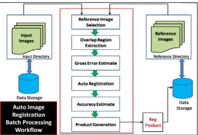
The software is designed to take job in a batch processing mode. The input/output image format for the software is GeoTiff. The software automatically selects the reference image for an input image using geo polygon intersection approach with a precondition that reference images and input images are positioned in known folders. The only requirement is that all the reference and input images should be in GeoTiff format for automatic process. The Batch Processing workflow of software framework is shown in Fig-1.
The software also computes the registration accuracy of the registered product in terms of root mean square error (RMSE) computed for the control points selected in the image. If the registration error is within the accuracy
threshold limit then it will automatically place the registered product in the output directory. If the registration error flag exceeds accuracy threshold limit then the registered product will be moved to the fail directory configured by the user.
4.1. Features of AIRS
x Handles Multiple Map Projections using dynamic link library 15.
x Automatic Reference Selection and overlap region extraction by polygon intersection.
x Gross Error Estimation between input and reference image.
x Generates date wise Software Usage Report.
x Registration Accuracy Report for each job.
x Fully automatic software system for image registration without any manual intervention.
Fig. 1. Precise Georeferencing Workflow 5. Experimental Setup and Results Achieved
The experiment was setup to register multiple images acquired from Cartosat-2A and Cartosat-2B spacecrafts. The input Cartosat images are system level geo corrected using physical model which needs orbit, attitude and camera level details as sensor parameters. Those images have varying location accuracy with respect to the ortho rectified Quick Bird reference images in cartographic reference system. The Table-1 shows the satellite/sensor used for experimental setup. The Table-2 tabulates the location accuracy error computed for Cartosat-2A and Cartosat-2B scenes with respect to Quick Bird Reference system.
Table-1. Sensor Information for Experiment
Satellite/ Sensor Spatial Resol (Metres) Swath (km) Spectral Band (microns) Cartosat-2A (PAN) 0.8 9.7 0.5-0.75 Cartosat-2B (PAN) 0.8 9.6 0.5-0.75
Quick Bird
(PAN) 0.6 16.5 0.76-0.85
Table-2. Location Accuracy Error
S.No Satellite/Sensor Deviation
in Easting (Metres) Deviation in Northing (Metres) 1 Cartosat-2A -292.6175 214.093957 2 Cartosat-2B 408.6 504.6
To improve the location accuracy of the Cartosat images, we need to perform the automatic precise georeferencing using unified software framework developed which is powered with advanced techniques already discussed in the beginning of this article. An experiment was performed using available Cartosat-2A/2B images. The input is stored in Storage Area Network (SAN) in a folder different to the reference images archive folder which is used by Auto Image Registration Software (AIRS) to select the corresponding reference images and do the required alignment using image registration techniques in a batch workflow described in Fig-1. The pictorial representation of the architectural setup is shown in Fig-2.
Fig. 2. Hardware Architecture for AIRS Software
To evaluate the performance of image registration, the root mean square error is calculated using pruned control points obtained by the accuracy estimate module stated in Fig-1.
ܴܯܵܧ= ටଵ
ேσ ฮܺെ ܺ ฮప ଶ ே
ୀଵ (6) Where N=Total number of matched points,
X୧are the (X୧, Y୧)coordinates in the master image,
Xనare the (Xన, Yన) estimated coordinates based on the effective transformation model.
The registration accuracy of Cartosat images thus achieved is shown in Table-3 which is within acceptable limits and below the accuracy threshold limits set by user.
Table-3: Registration Accuracy Table
S.No Area
Number
Satellite/Sensor RMSE (in
meters) 1. Area-1 Cartosat-2B 5.808191 2. Area-2 Cartosat-2A 1.318720 3. Area-3 Cartosat-2A 4.194457 4. Area-4 Cartosat-2A 3.813757 5. Area-5 Cartosat-2B 3.268427 6. Area-6 Cartosat-2A 5.701447 7. Area-7 Cartosat-2A 5.567656
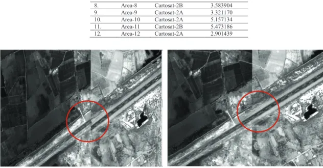
8. Area-8 Cartosat-2B 3.583904 9. Area-9 Cartosat-2A 3.321170 10. Area-10 Cartosat-2A 5.157134 11. Area-11 Cartosat-2B 5.473186 12. Area-12 Cartosat-2A 2.901439
(a) Before Processing (b) After Processing Fig. 3. Cartosat-2A Auto Geo-Processing Results (Input: Cartosat-2A, Reference- Quick Bird)
(a) Before Processing (b) After Processing
Fig. 4. Cartosat-2B Auto Geo-Processing Results (Input: Cartosat-2B, Reference- Quick Bird)
6. Conclusion
In this paper, we introduced an automatic precise geo referencing software workflow using advanced image processing techniques. The experimental results show that georeferencing performance in input Cartosat images using auto batch workflow improves the overall accuracy. The AIRS software was designed and implemented for operational use in huge data products archive. It provides us scope to upgrade the satellite image geometric quality using reference images of higher geometric accuracy in a fully automatic manner. Future scope for this work can be taken up in registration of images with cloud and noise using the intensity based techniques by involving suitable metrics and optimizers. Automatic tuning of the registration parameters for overall increase in the performance and accuracy is also a demanding problem. Generation of information products such as fusion product, at-sensor
reflectance product by implementing advance algorithms in an unified software framework and update remote sensing image archives with rich source of information and knowledge is always an important development.
Acknowledgements
The authors thankfully acknowledge Shri A.S Kiran Kumar, Director, Space Applications Centre, ISRO for giving us support and encouragement. We also thank Shri Santanu Chowdhury, Deputy Director, SIPA, Space Applications Centre, ISRO for his technical guidance.
References
1. Toutin Thierry. Geometric Processing of Remote Sensing Images, Models, Algorithms And Methods. International Journal of Remote Sensing; 2003.
2. Mahammad Sazid, Ramakrishnan R. GeoTIFF - a Standard Image File Format for GIS Applications. Map India. New Delhi; 2003. 3. Misra Indranil, Kaur Rajdeep, Moorthi Manthira S, Dhar Debajyoti, Ramakrishnan R.An efficient algorithm for automatic fusion of
RISAT-1 SAR data and Resourcesat-2 Optical images. International Conference on Intelligent Human-Computer Interaction (IHCI); 2012. 4. Brown LG. A Survey of Image Registration techniques. ACM computing Surveys;1992. p. 325-376.
5. Zitova Barbara, Flusser Jan. Image registration methods: a survey. Image and Vision Computing 23:977–1000; 2003.
6. Mishra Gaur Neha, Mohammad Sazid and Sharma Vivek. Template based HDF5 Satellite digital data product generation software. International Conference on Data Science & Engineering (ICDSE); 2012.
7. Dowman IJ. Automating Image Registration And Absolute Orientation: Solutions And Problems. Photogrammetric Record 16(91): 5–18; 1998.
8. Schmid Cordelia, Mohr Roger, Bauckhage Christian. Evaluation of Interest Point Detectors. International Journal of Computer Vision 37(2) p151–172; 2000.
9. Harris C, Stephens MJ. A combined corner and edge detector. Alvey Vision Conference; 1988. p. 147–152.
10. Misra Indranil, Moorthi Manthira S, Dhar Debajyoti, Ramakrishnan R.An Automatic satellite image registration technique based on Harris corner detection and Random sample Consensus (RANSAC) outlier rejection model. IEEE Recent Advances in information technology ISM Dhanbad India; 2012.
11. Fischler MA, Bolles RC. Random sample consensus: A paradigm for model fitting with applications to image analysis and automated cartography. Communications of the ACM; 1981.24(6). p. 381–395.
12. Misra Indranil, Moorthi Manthira S, Ramakrishnan R.Evaluation of Random Sample Consensus (RANSAC) Model for Satellite Image Registration. CSI Conference Ahmedabad Chapter; 2011.
13. Zuliani Marco. Computational Methods for Automatic Image Registration. University of California Santa Clara; 2006.
14. Moorthi Manthira S, Kaur Rajdeep, Sivakumar R, Ramakrishnan R.Performance Study of Optimization Methods for Intensity Based Automatic Satellite Image Registration. International Journal of Imaging and Robotics ; 2012.p.101-110.
15. Beazly David, Ward Brian, Cooke Ian. The Inside Story on Shared Libraries and Dynamic Loading. Scientific Programming Sep/Oct 2001.