This page has been reformatted by Knovel to provide easier navigation.
13
Bearings and
bearing metals
Contents
13.1 Introduction 331 13.2 Bearing design 331 13.2.1 Wall thickness 331 13.2.2 Interference fit 331 13.2.3 Locating tangs 332 13.2.4 Free spread 33213.2.5 Loading on crankpin and main bearings 333 13.2.6 Prediction of oil film thickness 333
13.2.7 Grooving configuration 334 13.2.8 Clearance 335 13.3 Bearing damage 335 13.3.1 Abrasion 335 13.3.2 Fatigue 336 13.3.3 Corrosion 336 13.3.4 Wiping 337 13.3.5 Cavitation 337 13.3.6 Fretting 337 13.3.7 Design faults 337 13.3.8 Incorrect assembly 338 13.3.9 Environmental factors 338 13.3.10 Geometric factors 339
13.4 Slow-speed engine crosshead bearings 339
13.5 Bearing metals 340
13.5.1 Fatigue strength 340
13.5.2 Scuff resistance 340
13.5.3 Wear resistance 341
13.5.4 Cavitation erosion resistance 341
13.5.5 Overlays 341
13.5.6 White metals 342
13.5.7 Copper-lead and lead-bronze alloys 343
13.5.8 Aluminium-tin alloys 344
13.5.9 Aluminium-silicon alloys 345
13.1 Introduction
Any bearing can be simply defined as a support or guide which at the same time allows relative movement to take place between two bodies. In a diesel engine, the principal bearings are those which allow rotation of the crankshaft about its own longitudinal axis in the main engine entablature, and those between the connecting rod and crankshaft. In modern engine terminology a bearing has come to mean the component fitted between the journal and either the main bearing housing or the connecting rod, the shaft being supported in the bearing via an oil film. Figure 13.1 indicates the interaction between the various components in any engine bearing assembly, and the environment within which the bearing system must operate1.
The co-operating surface, the lubricant and the environment all place constraints on the bearing, the resulting design usually being a compromise between various conflicting requirements. In relation to the bearing itself, the choice is usually restricted to material and geometry. However, environmental factors have to be taken into serious consideration at the design stage if a reliable system is to be achieved.
13.2 Bearing design
13.2.1 Wall thickness
To achieve optimum utilization of space, reliability and re-peatability of the bearing assembly, thin shell bearings have been almost universally adopted in modern diesel engines, and fitted retrospectively into many older engines. Such a bearing allows the use of a wider range of surface lining materials than would otherwise be possible.
The thin shell bearing is a precision made pre-finished component consisting of a steel backing with a thin coating of the most appropriate lining material necessary to provide sufficient strength for the applied loading and compatibility with the general environment. The overall thickness/diameter ratio is not critical, but typically varies from 0.05 at 40 mm diameter to 0.02 at 400 mm as shown by Figure 13.2.
13.2.2 Interference fit2
The assembled form of a thin shell bearing is dictated by the
Housing diameter [mm]
Figure 13.2 Wall thickness/diameter for thin wall bearings
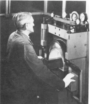
tolerance to which it can be manufactured, and by the housing into which it fits. To ensure conformity of the bearing shell to its housing, an accurate interference fit has to be provided. This is obtained by means of an excess peripheral length in each half-bearing which has to be closely prescribed to allow inter-changeability, requiring precise quality control of every half-bearing in a checking fixture (Figure 13.3}. On assembly the excess peripheral length creates a circumferential stress around the bearing, and a radial contact pressure between the bearing back and the housing bore. This contact pressure resists relative movement, thus preventing fretting. Unfortunately, there is no theoretically correct level; housings with high flexibility require more contact pressure than stiffer ones. On early engines, having thin shell bearings, a contact pressure as low as 2MPa was usually sufficient to resist fretting, but as engine ratings increased, and housing stress analysis became more sophisticated, higher pressures became necessary, often reaching 8-10 MPa today. In these very high interference fit assemblies, particular care has to be taken to ensure that the joint face clamping bolts have sufficient capacity to assemble the bearing, and to resist dynamic separating forces generated by engine operation.
As the contact pressure is increased for any given bearing size, the circumferential stress increases to the point where the
Crosshead bearings ISO range Wal l thicknes s [mm ]
Figure 13.1 The bearing
system-interaction between components and environment
Surface 1 Bearing Surface 2 Shaft Geometric Form 1. Dimensional 2. Surface finish 3. Features Material 1. Composition 2. Strength 3. Hardness 4. Compatibility 5. Corrosion resistance Lubricant 1. Viscosity (coefficient of) 2. Stability 3. Compatibility 4. Adhesion 5. 'Oiliness' 6. Bulk modulus 7. Additives Geometric Form 1. Dimensional 2. Surface finish 3. Bore profile 4. Features Material 1. Composition 2. Strength and ductility 3. Fatigue strength 4. Compatibility (seizure resistance) 5. Conformability 6. Embeddability 7. Corrosion resistance Applied Resultant 1. Minimum film thickness (hmin) 2. 'Friction' generated heat 3. Power loss 4. Bearing temperature 5. Lubrication outlet temperature 6. Lubricant supply
press, and temp. 7. Heat removal 8. Contamination 9. Vibration 10. Electrical potential 1. Load cycle 2. Sliding velocity 3. Temperature 4. Clearance 5. Supporting housing (a) Dimensional (b) Distortion (c) Alignment
Figure 13.3 Checking peripheral length of a thin shell bearing steel backing begins to yield adjacent to the joint faces. Knowing the combined effect of bearing steel yield strength and the friction force for bearing assembly, a wall thickness can be determined which will avoid yield, although in some automotive-type engines this may not be feasible.
Increased contact pressure requires a greater bolt tension for fitting bearing caps to their opposite half-housings, and as higher values are incorporated, measurement checks should be carried out on prototype assemblies to ensure that satisfactory closure of the housing joints occurs. Figure J3.4 shows a convenient method of checking this closure, the micrometer readings being taken as the bolt load is gradually increased. Insufficient bolt pre-load would result in fretting between the bearing and housing, and could allow the housing joints to separate, giving rise to high dynamic loading of the bolts, with possible fatigue fracture. To reduce the tendency to fretting, it is recommended that the centre line average (CLA) of the housing bore surface finish should not exceed 1.6 /^m. Bearing backs are typically 0.8 j^m CLA surface finish and, in highly loaded zones, should not be unsupported. Cyclic variation of hydrodynamic oil pressure on
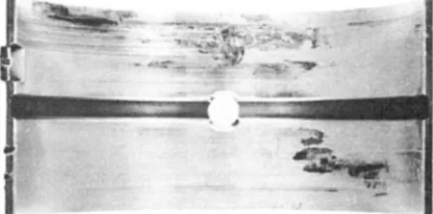
the bearing surface will cause the bearing to flex in these unsupported regions. If, for example, there are grooves or oil holes behind the bearing surface, fretting will almost certainly occur. If flexure is sufficiently great, the lining material on the bearing surface can also suffer fatigue damage. Figure 13.5 shows fretting damage on the back caused by a combination of insufficient interference fit and lack of support. The resulting flexure has also caused the lining material on the bore surface to fatigue.
Provided a bearing is manufactured to the defined length and wall thickness limits, and the housing and bolting arrangements are satisfactory, correct assembly should be achieved every time, with bearing shells being interchangeable. However, locating tangs and free spread greatly assist correct assembly of thin shell bearings, particularly replacement in situ.
13.2.3 Locating tangs
Locating tangs allow correct axial positioning of bearing shells thereby ensuring alignment of oil transfer passages and clearance between the ends of the bearing and crankshaft fillets. The tang is located in a corresponding recess in the housing and must be a clearance fit, otherwise the bearing surface may distort. It is also advantageous to relieve the tang below the level of the bearing joint face, thus reducing localized pressure on the tang during assembly.
Tangs are not intended to resist rotation of the bearing shell; that is achieved by the contact pressure. If, under seizure con-ditions, this contact pressure cannot prevent rotation, the tangs are either sheared or flattened.
13.2.4 Free spread
Free spread is the term given to the excess dimension across the bearing joints with the bearing in its free state, compared with the housing diameter. This allows the bearing to be positively located radially and should generate sufficient friction to hold the shell in its housing even when inverted.
Following operation in an engine, bearings may show a loss of free spread on removal for the following reasons: (i) The lining of a steel-backed bearing, because of its higher thermal expansion, can yield in compression at operating temperature producing a residual tensile stress when cooled to room temperature. This effect becomes greater with higher lining to steel thickness ratio.
(ii) A high radial temperature gradient across the steel backing, due to malfunction, can cause differential yield and therefore additional free spread loss.
(iii) Relief of strains induced during fitting or by the manufacturing and machining processes.
Figure 13.5 Fatigue and fretting damage due to insufficient interference
fit and unsupported region of the bearing back
The forces which result in free spread loss after releasing the bearing from its housing are of relatively small magnitude and will not cause malfunction of the bearing whilst in operation. Problems only arise upon reassembly, particularly if one half has negative and the other positive free spread. The half with the negative free spread may become trapped against the shaft and lead to overheating or seizure. Therefore bearings with negative free spread should not be refitted.
13.2.5 Loading on crankpin and main bearings3
The load on both crankpin and main bearings varies in magnitude and direction with time. When studying the performance of such bearings, it is necessary to determine these loads, over each complete loading cycle. Such data are usually presented as polar load diagrams.
The loads on the connecting rod big end bearing can be attributed to three components; reciprocating inertia forces, rotating inertia forces and gas forces, as shown by the two diagrams of Figure 13.6. Vector addition of these forces at regular intervals of crank angle results in the typical polar load diagram of bearing forces for one loading cycle shown in Figure 13.7. The loads on main bearings are partly due to force reactions from the big end bearings and partly due to out of balance of the crankshaft. The out of balance of the crankshaft is usually reduced by the use of balance weights. When considering the forces from the big end bearing, it is necessary to orientate them to the same non-rotating datum as the main bearing (i.e. relative to a cylinder axis).
In a multi-cylinder engine, which generally in the modern engine has a main bearing between each crank pin, the force on that main bearing is usually assumed to consist only of forces from components in the two crank bays immediately adjacent to that bearing. The resultant force is obtained by treating the crankshaft as a series of simply supported beams resting on supports at the main bearings (statically determinate method). By this means, component forces closest to any one main bearing have the largest effect on that bearing. Then, in much the same way as the polar load diagram of the big end bearing is built up over a complete loading cycle, the overall dynamic load pattern
on each main bearing is obtained by vector addition of all the forces at each interval of crank angle.
13.2.6 Prediction of oil film thickness
Once the dynamic load pattern as a function of time has been etablished for any bearings in the engine, it is possible to predict the minimum oil film thickness, and its position on the bearing surface, at each position of the load diagram. Several different procedures exist for this prediction, varying in complexity and
Motion
Resultant force on bearing
Resultant on pin
Figure 13.6 Components of load acting
on large end bearing
Connecting rod axis
Figure 13.7 Typical large end
hence in validity with the real case. Each method makes some attempt to solve Reynolds equation governing the performance of hydrodynamic bearings. Some of the methods available are:
(a) Hand calculation, using an equivalent speed concept4'5'6 (b) Graphical procedures for the complete locus, using mobility
methods7.
(c) Approximate method to predict the minimum film thickness in the cycle where 'squeeze intervals' predominate8. (d) Computer methods which predict the complete journal
locus?'9'10
(e) Inertia load studies" (f) Experimental results8.
All these methods are thoroughly reviewed by Campbell et <3/.8, but whilst each technique has specific advantages in particular circumstances, those most generally employed involve the use of computer methods to predict the complete journal locus over the whole of each loading cycle. The advantage of rapid, low-cost computer programs is that predicted results can be achieved and compared for a large number of different types and sizes of engines at various operating conditions. With the greater flexibility afforded by the use of computers, bearing analysis will continue to advance, but whilst it is already possible to give some consideration to housing, crankshaft and bedplate distortion, the most common computer techniques still treat the crankshaft as a series of simply supported beams. For medium- and slow-speed engines, this is probably realistic due to the high crankshaft stiffnesses demanded by stress limits, and the high standard of bearing alignment enabled by current machine tools and production methods.
Other basic assumptions usually include: perfect alignment of shaft and bearing through the loading cycle; truly circular shaft and bearing; infinitely rigid bearing housing and journal; viscosity unaffected by variations of temperature and pressure around the bearing and through the cycle; and that negative oil film pressures can be neglected.
From the numerous bearing calculations carried out by the Glacier Metal Co., with use of computer calculation procedures incorporating the above assumptions, it has been possible to prepare a graph of computed minimum film thicknesses for different shaft diameters (Figure 13.S).This facilitates comparison of calculated values for any other engine against the norm, but does not allow absolute limits to be set. Deduced levels of 0.000 008 per unit diameter for large ends, and 0.000 Ol per unit of diameter for main bearings have been superimposed. Further experience, improved production methods, filtration, etc., will presumably allow these levels to be reduced in the future.
A similar exercise was carried out to compare the calculated maximum specific bearing loads (Figure 13.9} for the same engines as with the minimum film thicknesses of Figure 13.8. The wide scatter band shown by these results is to be expected, but as with the film thickness values, they allow direct comparison with existing practice for any engine design, particularly at the design stage.
13.2.7 Grooving configuration
The simplest grooving arrangement is to have a central circumferential groove of 360° extent in all bearings. This allows unimpeded oil transfer from one area to another. Hydro-dynamically, the absence of all grooving is the optimum, and so a compromise between the hydrodynamic requirement and the physical requirement of supplying oil has to be made. This often results in the so-called partially grooved bearing in which there is a central circumferential groove of less than 360° extent. Such a partially grooved bearing usually allows an increase of
Crankshaft diameter (mm)
Figure 13.9 Predicted maximum specific load as a function of diameter
the order of 100-200 per cent in the oil film thickness in the original thinnest film region.
When partially grooved bearings are adopted, a system of interconnected cross drillings in the crankshaft is necessary to allow a constant supply of oil to each bearing, or to the piston. Positioning of, and oil supply passages to, partial grooves can be critical. Predicted oil film thicknesses are based on the
x - Large end or crankpin bearings • - Main bearings x - Large end or crankpin bearings • - Main bearings Crankshaft diameter (mm)
Figure 13.8 Predicted minimum oil film thickness as a function of
diameter Calculate d minimu m oi l fil m thicknes s (mm ) Maximu m specifi c loa d (N/mm 2)
assumption that oil is available at all times within the clearance space to allow a film to be generated. Thus any arrangement of partial grooving must allow sufficient oil to be supplied to the required region of the bearing surface.
Two further distinct disadvantages of the partial groove design of bearing are described in the section on bearing damage. These are differential wear of the crank journal, and cavitation erosion of the bearing surface12.
Thus one should not automatically design partially grooved bearings purely on the basis that increased oil film thickness will be achieved. Alternative methods of improving the film thickness should also be investigated if improvement is consi-dered necessary. This includes increase of bearing dimensions, adjustment of engine masses and modification of firing orders. 13.2.8 Clearance13
There are no precise limits on what clearance there should be between bearing bore and journal surface, and it is often determined by experience. As clearance is increased, the theoretical load-carrying capacity is reduced, but this assumes that bearing temperature and oil viscosity are constant. However, an increased quantity of oil can be pumped through the bearing, thus keeping its temperature lower. Too high a value of clearance in any plane around the bearing may also result in cavitation erosion damage12. Thus there is a range of clearance over which optimum bearing performance can be expected. Figure 13JO presents curves of a semi-empirical nature based on a theoretical heat balance for steadily loaded bearings. These curves can be considerably simplified, by the superposition of a practical band of shaft sizes over a given speed range. Comparison of these two sets of curves results in a generalized value for minimum diametral clearance of 0.00075 x bearing diameter. Manufac-turing tolerances of shaft, housing diameter and bearing wall thickness then result in a maximum design clearance somewhat greater than 0.001 x bearing diameter.
When oil film thickness computations are carried out on a comparative basis for various values of clearance, allowing for the lower temperature and higher viscosity corresponding to the larger clearances, it is often found for the medium-speed range of engines that optimum oil film conditions occur at a clearance of approximately 0.001 x bearing diameter, but over a region
0.000 75-0.0015 x bearing diameter there is usually only a small change in the predicted conditions. This upper limit of 0.0015 x bearing diameter can be used as an indicator for limiting wear during engine operation, although absolute limits for any particular engine type can be determined only by experience with that engine type. An additional practical limit can also be imposed by oil pump capacity.
13.3 Bearing damage
The main difficulty of establishing separate categories of damage is that they are often related, or that damage initiated by one cause can result in another effect. However, the commonest types of bearing damage likely to be experienced by diesel engine operators can be approximately classified under the following 10 categories (Sections 13.3.1 to 13.3.10). 13.3.1 Abrasion
This is still probably the most common form of bearing damage, even though filtration standards are generally very high. Long term operation with very fine debris in the oil, or short term operation with coarser contaminant can result in abrasion and scoring of the surface of a bearing (Figures 13.11 and 13.12) roughening it to such an extent that overheating can occur due to the surface roughness penetrating the thin oil film. Alternatively, ferrous particles can become embedded in the bearing lining or soft overlay and become work hardened to a level higher than that of the crankshaft, resulting in wear and scoring of the shaft. The presence and degree of ferrous contamination in bearing surfaces can be detected by the technique known as iron printing. In essence, this consists of obtaining a chemical reaction between the embedded particles and a weak solution of potassium ferrocyanide held in a filter paper placed on the bearing surface. Generally speaking, a worn bearing should be renewed, when discovered, if approximately one-third of the projected area of copper-lead or nickel interlayer is exposed. Wear through to expose underlying tin-aluminium is not necessarily a cause for renewal, unless the bearing shows signs of overheating, scuffing, or entrapment of particles proud of the bore surface.
Bearing diameter D (mm)
Figure 13.10 Minimum diametral clearance
Practical operating range of speed/diameter
Theoretical Cd min
N = Engine speed in rev/min D = Bearing bore diameter Cd = Diametral clearance Minimu m diametra l clearanc e C d mi n (mm )
Figure 13.12 Severe scoring by a few large particles 13.3.2 Fatigue
With the general introduction of stronger bearing linings, and improved calculation procedures, fatigue due to design overload is uncommon. Typical fatigue damage of white metal is shown in Figure 13.13 due to a combination of load, high temperature, and the inconsistency of white metal structure resulting from the direct lining of a large variable-cross-section housing. Fatigue damage of the stronger lining of the modern diesel engine is usually a consequence of some other problem, as was shown in Figure 13.5.
Fatigue of the galvanically applied overlay plate is shown in Figure 13.14. This layer is applied to the majority of medium-speed engine crankshaft bearings to accommodate oil-borne debris, misalignment and operating deflections.
13.3.3 Corrosion
The different bearing alloys suffer corrosion under different conditions.
Tin-base white metals, particularly in the slow-speed diesel engine, can form a hard, dark (almost black) brittle surface deposit when water is present in the lubricating oil. This has been found to be tin oxide, formed by conversion of the tin matrix of the lining by an electrochemical process14, and becomes thicker with time. Layers as thick as 0.25 mm have been found. Under these conditions, the bearing becomes prone to overheating and seizure. Alternatively, due to the brittle nature of the layer, it can flake off the surface, leaving a generally pitted appearance. Copper-lead lining, if exposed to a lubricating oil which has thermally degraded to form organic acids and peroxides, or become contaminated by sulphur containing fuel oils, blow-by of products of combustion of such fuels, or cooling water with antifreeze additives, is prone to corrosion of the lead phase of the lining, be this either of the cast or sinter type. Such attack results in a porous, extremely weak, copper matrix which is easily fatigued by the dynamic loads applied to the surface (Figure 13.15).
Aluminium-based linings are completely resistant to engine oils, and to their high-temperature degradation products. However, in direct contact with water, a film of aluminium oxide can form in the bore, together with corrosion of the steel backing and Figure 13.11 Abrasion by small contaminant over a long period
Figure 13.13 Fatigue damage in direct-lined white metal crosshead
bearings
Figure 13.14 Fatigue of an overlay-plated surface
Figure 13.15 Loss of surface material caused by corrosion of the
possible lifting of the lining material, although in an oil environ-ment in an engine, this is virtually impossible.
13.3.4 Wiping
This type of damage (Figure 13.16} can occur with any lining material, and is caused by insufficient lubricating and cooling oil on the bearing surface. This results in overheating and eventually melting of the lowest melting-point phase of the lining alloy. Potential causes of insufficient oil on the bearing surface include inadequate generated oil film thickness, insufficient clearance, housing distortion, restriction in oil supply system, excessively worn bearings in other locations and inadequate oil pump capacity.
13.3.5 Cavitation
Cavitation erosion damage to bearing surfaces is a form of micro fatigue cracking, initiated by the collapse of vapour cavities, and is thoroughly discussed in Reference 12. Typical damage to a large end bearing is shown in Figure 13.17 and to a main bearing in Figure 13.18.
13.3.6 Fretting
Figure 13.19 shows a severe case of fretting of a bearing due to insufficient contact pressure, local welding and tearing having taken place between the bearing back and housing bore, resulting in transfer of metal from one to the other. Where fretting of the joint faces of the bearing occurs, as shown in Figurel3.20, this usually implies inadequate joint face clamping force. Fretting of the housing joints can also be expected under these conditions. Before fitting new bearings where fretting has occurred, all trace of fretting build-up in the housing must be removed to avoid premature catastrophic damage of the new bearing. 13.3.7 Design faults
Major design faults will not generally be evident in production engines because they would have been found out very quickly during pre-production development testing. Some faults however, do not necessarily cause problems, but require certain other conditions to exist also. An example of this would be blind location features, such as a dowel fitting in a hole in the bearing back. If positioned away from the heaviest loaded region of the bearing, this would not cause problems, unless during assembly or re-fitting the dowel was not located correctly in the hole.
A bearing load diagram which results in an almost pure rotating load pattern, i.e. where the load vector on the bearing surface travels at approximately shaft speed, can result in wiping and overheating even though the theoretical oil film thickness is
Figure 13.16 Wiping damage
Figure 13.17 Cavitation erosion of a large end bearing
Figure 13.18 Cavitation erosion of a main bearing
Figure 13.19 Fretting of a bearing back due to insufficient contact
pressure
Figure 13.20 Fretting of a bearing joint face due to inadequate bolt
greater on that bearing than on others in the same engine. Such a condition is more likely to exist in an engine running on very light load and full speed. The solution is to fit larger balance weights to counteract the inertia forces of the crankshaft and connecting rods. Adverse load patterns can be further aggravated by incorrect positioning of oil holes in journal surfaces, and damage due to this cause is typified by Figure 13.21. 13.3.8 Incorrect assembly
The commonest causes of incorrect assembly are associated with locating devices. Incorrect positioning will mean that oil feed connections are misplaced and can block off the oil feed. Incorrect location of a tang into its recess means that the bearing back will not be in contact with the housing, and the clearance between the bearing bore and the crankshaft can be lost, resulting in local overheating of the bearing surface, and possibly seizure. Having located the bearing correctly into its housing, care must be taken to ensure that the housing bolts are correctly tensioned. Insufficient bolt load due to incorrect tightening can result in the damage shown in Figure 13.20 and also excessive dynamic stressing of the bolts and ultimate fatigue fracture. The bolts should also be tensioned in the prescribed sequence given in the engine manual. Failure to follow the same sequence may result in a modified bore shape and unsatisfactory bearing performance.
13.3.9 Environmental factors 13.3.9.1 Electrical discharge
On generator installations, with inadequate earthing, a discharge of current can occur through the oil film between the journal surface and the bearing bore, resulting in fine, cleanly defined pitting of the bearing surface (Figure 13.22). Damage such as this has been found to occur with an electrical potential in excess of only 50 mV.
13.3.9.2 Journal wear ridge
Wear of the journal surface can occur due to embedded hard contaminant in the bearing surface. Less wear occurs in the region associated with grooves, gradually producing a ridge on the journal surface, which in turn causes wear of the bearing surface (Figure 13.23) of partially grooved bearings. 13.3.9.3 Static fretting
The damage shown in Figure 13.24 is caused by vibration of a
Figure 13.24 Damage to bore surface caused by crankshaft vibration
crankshaft within the bearing clearance. The term 'static' comes from the fact that such damage only occurs when the engine is not running. The damage can occur during transport of assembled engines to site. In marine installations, generating sets mounted on flexible tank tops are prone to similar damage. In such cases, the simplest palliative is to ensure that oil is pumped through the bearing clearance every few hours while the engine is inoperative, although in very severe instances it may also be necessary to redesign the mountings.
13.3.9.4 Nitride damage
The specific form of damage shown in Figure 13.25 characterized by the vee chevrons is caused by iron nitride particles from a
Figure 13.21 Surface damage due to incorrectly positioned oil hole
Figure 13.22 Pitted surface caused by electrical discharge
Figure 13.23 Wiping and overloading of a local region of the bore
Figure 13.25 Damage caused by iron nitride particles from a nitrided
journal surface
nitride-hardened shaft which has not had the thin friable layer ground off from the surface. To be sure of avoiding such damage, up to 0.02 mm needs to be removed.
13.3.9.5 Misalignment
Misalignment through whatever cause is typified by a 'D' pattern of wear, with the longest side on one end of the bearing, as Figure 13.26. Causes can be taper in the bearing housing or journal surface, debris trapped between shell and housing, bruising of the steel backing of the bearing shell or housing bore during assembly, taper through the bore of the bearing, or a variation in alignment of a series of main bearing bores along the engine. 13.3.10 Geometric factors
Severe wear of localized regions of the bearing surface are generally caused by specific geometric inaccuracies. Heavy wear in the axial centre region is usually caused by a 'barrelled' journal, whereas heavy wear at both ends of the bearing results from an 'hour glass' profile.
13.4 Slow-speed engine crosshead bearings
Thin shell bearings for probably the most arduously loaded of all engine bearings, the two-stroke crosshead assembly, were tested by the major engine builders in the early 1960s. Following such trials, they were gradually introduced into general pro-duction, and as loadings and conditions became even more arduous, the thin shell pre-finished bearing has become almost universally adopted in crossheads, and in several instances, in the bottom end and main bearings also.The basic problem encountered in direct-lined white metal bearings was lining fatigue (as shown in Figure 13.13). Adoption of thin shell bearings permitted an improvement in metallurgical structure and strength, particularly at the steel/white-metal bond line by the use of centrifugal casting and improved uniform cooling of the constant cross-section.
Moreover, once the pre-finished thin shell is adopted, it allows advantage to be taken of the better fatigue properties of the stronger lining materials. One engine range has had 40 per cent tin-aluminium-lined bearings incorporated from inception15. The thin shell bearing has other inherent advantages. Carrying of onboard spares is much more convenient, as is the re-fitting of replacements. Spares, when required urgently, are much more easily freighted and ship turn-round time is greatly reduced compared with that for the assembly shown in Figure 13.13.
The bearing geometry can be much more closely controlled as a result of specialist manufacture and absence of hand fitting. Optimum performance of the crosshead bearing has been obtained with the so-called bedded-are profile. This is a machinable form, repeatable within fine tolerance, that replaces the hand-scraped bedded-in form. The general configuration is shown in Figure 13.27. Over an arc of approximately 120°, symmetrical about the vertical centre line, the radial clearance between pin and bearing is almost zero. This is optimum because the crosshead bearing relies basically upon a squeeze film for lubrication. Axial grooves pitched at the swing of the crosshead pin allow oil to be swept onto the bearing surface. Small bleed grooves at
Figure 13.26 Surface wear associated with shaft misalignment
Figure 13.27 General configuration of a 'bedded arc' crosshead
bearing
Wall thickness
Lining
Steel Oil supply
hole
Bleed groove
the ends of the main axial grooves induce a flow of oil for added cooling, and also allow lubrication of thrust faces.
Manufacturing tolerances of bearing, pin and housing create a positive clearance between pin and bearing surface, but the application of a precision electroplated overlay, usually 0.02-0.03 mm thick, of a soft lead-tin on the precision-formed bearing bore profile, allows very rapid bedding-in without localized overheating and consequential fatigue cracking, and as such is extremely beneficial, even on white metal.
A different approach has been taken by one engine builder16, using an eccentric arrangement of bearings and pins where load is transferred from one bearing land to another during the total swing of the rod and pin. The adoption of separate shell bearings for each land, with eccentricity in the wall thickness, simplifies the achievement of the required assembly.
13.5 Bearing metals
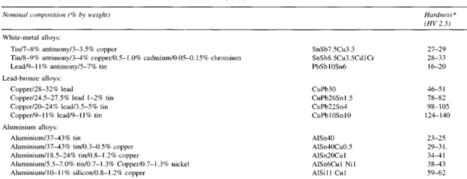
The purpose of the remaining sections of this chapter is to describe the materials used as linings for thin shell bearings, with particular emphasis again on crankshaft bearings. The most commonly used alloys are listed in Table 13.1.
To begin with, an outline is given of the properties of materials most relevant to bearing performance.
13.5.1 Fatigue strength
Lining fatigue occurs because of the cyclic nature of the loads applied to the bearings. Fatigue ratings for a range of bearing alloys are given in Figure 13.28. These results were obtained on a test rig in which a dynamic load is applied to a bearing via hydraulic resistance against an eccentric test shaft14. Results from test rigs cannot be used directly for design purposes. However, it is possible to rank materials in an order that correlates with their performance in engines, as illustrated by comparison of Figure 13.28 with Table 13.2, which contains fatigue limits of bearing materials derived from engine experience. 13.5.2 Scuff resistance
Scuffing, also known as seizure or scoring, is a result of local solid-phase welding ('pick-up') between the shaft and bearing surfaces. In extreme cases, scuffing leads to wiping and possibly to complete bearing seizure.
Fatigue rating, MPa
Figure 13.28 Fatigue ratings for a range of commercial bearing
alloys.
Table 13.2 Recommended maximum loadings (fatigue limit) for bearing
materials in slow- and medium-speed diesel engines
The ability of a bearing material to resist scuffing depends on three factors—compatibility, conformability and embeddability. Compatibility is an inherent tendency of a material to resist solid-phase welding. A conformable material, is able to deform under conditions of shaft misalignment, thereby reducing local load concentrations and maintaining an adequate oil film thickness. A material with good embeddability allows hard particles to embed in the surface of the bearing, thus reducing any abrasive damage which such particles can cause both to the bearing and the shaft.
With metallic bearing materials, both conformability and embeddability are related inversely to hardness. In Table 13.1
Material AlSn6CulNil CuPb26Snl.5 AlSn20Cul AlSn40Cu0.5 SnSb8.5Cu3.5CdlCr0.1 SnSb7.5Cu3.3 PbSb 10Sn6 Maximum loading (MPa) 38 38 35 20 14 12 12
Table 13.1 Composition and hardness of some commercial bearing alloys
Nominal composition (% by weight)
White-metal alloys:
Tin/7-8% antimony/3-3.5% copper
Tin/8-9% antimony/3-4% copper/0.5-1.0% cadmium/0.05-0.15% chromium Lead/9-11% antimony/5-7% tin
Lead-bronze alloys: Copper/28-32% lead
Copper/24.5-27.5% lead 1-2% tin Copper/20-24% lead/3.5-5% tin Copper/9-11% lead/9-11% tin Aluminium alloys:
Aluminium/37-43% tin
Aluminium/37-43% tin/0.3-0.5% copper Aluminium/18.5-24% tin/0.8-1.2% copper
Aluminium/5.5-7.0% tin/0.7-1.3% Copper/0.7-1.3% nickel Aluminium/10-11% silicon/0.8-1.2% copper
SnSb7.5Cu3.3 SnSb8.5Cu3.5CdlCr PbSblOSn6 CuPb30 CuPb26Snl.5 CuPb22Sn4 CuPbI OSn 10 AlSn40 AlSn40Cu0.5 AlSn20Cul AlSn6Cul Nil AlSiIl CuI Hardness* (HV 2.5) 27-29 28-33 16-20 46-51 78-82 98-105 124-140 23-25 29-31. 34-41 38-43 59-62 This is the hardness of a 0.25-0.50 mm thick lining on steel, in the form of a 50 mm diameter half-bearing. Flat strip or larger bearings have lower hardness.
Lining fatigue overlay overlay overlay overlay overlay
typical hardness values are given for the range of bearing alloys. Compatibility is less easy to quantify; in a test used in the Glacier Metal Co., a shaft runs in a bush in a stop-start cycle with the load maintained during the stop part of the cycle. Lubrication is limited to approximately one drop of oil per minute. The load is increased until scuffing occurs, indicated by an increase in running temperature. Alignment between shaft and bearing surface is good so that resistance to scuffing depends primarily on the compatibility of the bearing material. The relative performance of bearing alloys on this test rig is shown in Figure 13.29.
Comparison of Figures 13.28 and 13.29 and Table 13.1 shows that, in general, bearing alloys with high fatigue strength have high values of hardness as well as relatively poor compatibility. Thus, selection of a bearing material is always a compromise between fatigue strength and scuff resistance. As a general guide, the least hard material is chosen which has sufficient fatigue strength for the application.
13.5.3 Wear resistance
Many wear mechanisms have been proposed for different materials17, but for engine bearings only two need be considered: (i) 'severe abrasion' of the bearing and shaft by hard particles in the oil,
(ii) 'mild abrasion' of the bearing by asperities on the shaft. Wear rates in the two regimes may differ by a factor of up to 106. Mild wear without scuffing can be beneficial if it improves conformability between shaft and bearing.
The wear rate of a material is a highly system-dependent property, and test rigs provide an unreliable guide to performance in an application. In general, a harder material has greater resistance to 'severe abrasion' but a correlation between material properties and 'mild abrasion' resistance has not been established. 13.5.4 Cavitation erosion resistance
A simple test rig for producing cavitation erosion of bearing linings has been described12, in which cavitation is produced close to a bearing surface by an ultrasonically vibrating probe. Some results from this rig are shown in Figure 13.30 and suggest that cavitation erosion resistance depends on material type rather than mechanical properties. For each type of alloy, however, e.g. lead-bronze, increased hardness and strength produce increased cavitation erosion resistance. It should be noted that
Volume loss cm3 x 10 3
Figure 13.30 Cavitation erosion resistance of bearing alloys and
overlays. Volume loss measured after 10 min. Note different scale for lead-based alloys
the results in Figure 13.30 for the overlay compositions (PbSn 1 OCuS, PbSn 10 and Pbln6) were obtained under less severe conditions than for the other alloys. The two sets of results are not, therefore, directly comparable.
13.5.5 Overlays
Overlays are thin coatings (0.02-0.05 mm) of a soft alloy, usually lead-based. Commonly used compositions are given in Table 13.3. Their original purpose was to improve the corrosion resistance and compatibility of lead-bronze bearings although, being soft, they also have good dirt embeddability and con-formability. With cast lead-bronze linings a nickel interlayer, 0.002 mm thick, is normally applied to ensure the long-term integrity of the bond between overlay and substrate. Overlays can also be applied to the full range of aluminium alloy bearings. A nickel interlayer is again used, to protect the aluminium from chemical attack during deposition of the overlay.
Overlays are electrodeposited onto the bearing surface, normally after final boring. Lead/tin and lead/tin/copper are co-deposited directly, whereas lead and indium are co-deposited consecutively and diffused together by a heat treatment. Typical hardness figures are given in Table 13.3. In bulk these overlay compositions are weak, but are significantly stronger in the form of thin coatings. Figure 13.31 shows how fatigue strength increases as thickness is reduced. For a given thickness, lead/ indium overlays give slightly higher fatigue ratings than lead/ tin or lead/tin/copper.
Overlay fatigue usually occurs at a lower load than for the substrate material, as shown in Figure 13.28. However, even a fatigued overlay provides some protection for the substrate and the fatigue strength of a bearing is always higher when overlay plated, as illustrated in Figure 13.28 for aluminium/6% tin. This does not imply, though, that overlay fatigue can be ignored. With lead-bronze bearings for example, fatigue cracks in the overlay expose lead in the substrate to corrosion.
Table 13.3 Composition and hardness of overlays
Compatibility rating
Figure 13.29 Relative compatibility ratings (Sn-based white metal=10)
of bearing alloys
Nominal composition
Lead/ 10% tin Lead/ 10% tin/3% copper Lead/6% indium PbSnIO PbSnIOCuS Pbln6 Hardness (Hv 0.025) 9-10 12-15 8-9
Thickness mm
Figure 13.31 Fatigue-strength/thickness relationship for overlays Relative wear resistance is demonstrated by measurements obtained using the dynamically loaded bearing test rig, and results are shown in Figure 13,32, Lead/tin/copper has a higher wear resistance than lead/tin, which is in turn superior to lead/indium. These results concur with those reported by Schaefer19. The relatively poor wear resistance of lead/indium negates to some extent its high fatigue rating, since for a given wear life a thicker overlay is required which leads to a lower fatigue strength. Relative cavitation erosion rates are given in Figure 13.30. Lead/tin/copper has the highest resistance to cavitation, followed by lead/tin.
Tin or indium is necessary to improve corrosion resistance of the lead. The minimum levels required for adequate corrosion resistance are 3 per cent tin and 5 per cent indium20. Although these levels are below those in the as-plated overlays, in service, tin and indium are lost by diffusion into the substrate18. The result is formation of intermetallic compounds with copper or nickel in the substrate or interlayer2', and corrosion of the overlay if the tin or indium level falls below the safety limit. Loss of tin is demonstrated by results shown in Figure 13.33, which were obtained by heating sintered copper-lead bearings plated with lead/10% tin. It is sometimes claimed that a nickel interlayer eliminates tin loss. However, this is not so, as shown in Figure 13.33, although the rate of loss of tin is significantly reduced by the presence of a nickel interlayer. Increasing the tin content of the overlay is not a complete solution to the tin diffusion problem, since the rate of diffusion is correspondingly increased.
Lead/tin/copper overlays are more corrosion resistant than lead/tin, possibly because the rate of tin loss is lower with lead/ tin/copper as a result of the formation of copper-tin compounds
Time at 10O0C h
Figure 13.33 Diffusion of Sn from Pb/Sn overlays on Cu/Pb with and
without Ni barrier
within the overlay. Thus, the combination of high wear resistance, cavitation erosion resistance and corrosion resistance makes lead/tin/copper the preferred overlay for the modern highly rated medium-speed diesel engine, particularly when these operate on residual fuels.
13.5.6 White metals
Tin-based white metals are alloys of tin, antimony and copper, the most commonly used composition being tin/7.5% antimony/ 3.3% copper. The metallurgical structure (Figure 13.34) consists of a tin-antimony matrix which is strengthened by needles of copper-tin compound.
The effects of composition and method of manufacture on the mechanical and bearing properties of white metals have been described in detail by Pratt14. The effect of cooling conditions during production of bearing linings, referred to earlier, is demonstrated by the results in Figure 13.35. Rapidly quenched material, obtained during production of thin shell bearings, has a finer copper-tin compound distribution and a higher fatigue strength than slow-cooled linings obtained when white metal is cast directly into large bearing structures.
The fatigue strength of the basic white metal composition
Figure 13.32 Comparative wear resistance for overlays
Figure 13.34 Typical structure of SnSb7.5Cu3.3, Showing star-shaped
Cu-Sn needles in Sn-Sb matrix MPa on load Weigh t loss , g Ni barrier Ni barrier Fatigu e strengt h MP a Ti n conten t weigh t %
Fatigue rating MPa
Figure 13.35 Effect of casting method and composition on fatigue
strength of Sn-based white metals
can be increased by adding cadmium, which goes into solution in the matrix, and by adding trace quantities (0.1 per cent) of chromium, which refines the distribution of the copper-tin compound. By this means, it is possible to produce commercially a slow-cooled white-metal-lined bearing with a fatigue strength as high as a rapidly cooled or quenched lining (Figure 13.35). Conformability and embeddability of tin-based white metals are very good, as would be expected for a material of low hardness. Corrosion resistance is good, except when the lubricating oil is contaminated by water as described earlier. However, the outstanding characteristic of tin-based white metal is its compatibility, scuffing in service being virtually unknown. In conditions of oil starvation linings suffer wiping rather than scuffing and the wiped surfaces are capable of continued operation, which is not the case with most other bearing alloys. Lead-based white metals are basically alloys of lead, tin and antimony, containing 6-12 per cent tin and 10-15 per cent antimony. The structure of the 10 per cent antimony/6 per cent tin composition consists of a single-phase lead-tin-antimony matrix. At higher antimony contents, tin-antimony cuboids are formed. Another version contains 15 per cent antimony and 1 per cent arsenic, the structure in this case being a fine antimony-arsenic precipitate, in a lead-antimony matrix.
Cooling conditions during bearing manufacture affect mechanical properties similarly to tin-based white metal, although rapidly cooled lead-based linings must be annealed to provide adequate ductility. Likewise, minor additions of certain metals— arsenic, copper, cadmium or nickel—can increase the fatigue strength of a slow-cooled lining by refining the alloy structure. In comparison with tin-based white metals, the lead-based alloys are softer (Table 13.1} and hence have even better conformability and dirt embeddability. Fatigue strength is similar (Figure 13.28). Tin and antimony contents are generally high enough to avoid corrosion problems in most applications. Compatibility, as assessed on the stop-start test rig described above, is not as good as tin-based white metal (Figure 13.29} although in service, scuffing of lead-based white metal is generally not a problem. Wear and cavitation erosion resistance of the lead-based alloys are, however, inferior.
White metals were the first alloys developed specifically for plain bearings. Although their fatigue strength is relatively low, they are still widely used on account of their surface properties. Because of the rather better corrosion and scuff resistance of tin-based white metal, it is preferred to lead-based alloys in certain critical applications, e.g. crosshead bearings. For general applications, lead-based white metal bearings are significantly cheaper than their based equivalents, but even so, the tin-based alloys are, by tradition, used more widely.
13.5.7 Copper-lead and lead-bronze alloys
Historically, lead-bronze bearing linings were introduced when fatigue of white metal became a serious problem, as a result of
increased engine ratings. Modern thin shell bearings are made either by casting on to steel strip or by a sinter route, in which pre-alloyed powder is applied to steel and consolidated by sintering and rolling. All of the lead-bronze alloys in Table 13.1 can be made into bearings by either method; copper-lead linings with 30 per cent or more lead are made only by the sinter route.
The most widely used compositions lie within the range 22-26% lead/1-2% tin. The tin goes almost exclusively into the copper, and so the structure consists of a bronze matrix containing lead islands. However, the detailed structure depends on the method of manufacture, as illustrated in Figure 13.36 (a) and (b). Sintered linings tend to have a finer and more uniform lead distribution than cast alloys. In general, strip-cast linings are harder than sintered ones of the same composition.
The 22-26% lead/1-2% tin alloy has a high fatigue strength and is suitable for most medium- and high-speed diesel engines. It is always overlay-plated, primarily to protect the lead phase from corrosion but also because the alloy is relatively hard and incompatible (Figure 13.29}. For medium-speed applications the overlay thickness may be as high as 0.05 mm, but where higher load-carrying capacity is required a thickness of 0.025 mm is used (see Figure 13.31.} Hardened shafts, of minimum hardness 300 HV, are recommended.
An improvement in surface properties and dirt embeddability, at the expense of fatigue strength, is obtained with copper/30% lead. Even so, this alloy is overlay-plated for corrosion protection. Stronger linings can be made from copper/22% lead /4% tin. Such alloys can be used in engines which are too highly rated
Figure 13.36 Typical structures of CuPb26Sn1.5; (a) sintered; (b)
cast. The different lead distributions and matrix structures are shown
(strip-cast) (rotary-lined)
for the 26% lead/1.5% tin alloy; a thin overlay and a hardened shaft are required.
The copper/10% lead/10% tin alloy is very strong, but is too hard and prone to scuffing to be used as a crankshaft bearing. However, it is widely used for small end bushes, which are very highly loaded. In order to avoid scuffing, a hardened gudgeon pin (700 HV) is used, with a very fine surface finish. 13.5.8 Aluminium-tin alloys
The major impetus for the development of aluminium-tin bearings was their superior corrosion resistance relative to lead-bronze. Four aluminium-tin alloys are used in diesel engines, and their nominal compositions are given in Table 13.1. Bearings are made by roll bonding the alloy to steel strip via an interlayer (for aluminium-tin alloys) which is usually aluminium.
Aluminium/6% tin is a long-established bearing material22, developed originally for cast bearings. Copper and nickel are added to increase strength; copper is a solution hardener and the nickel forms a fine dispersion of nickel-aluminium compounds, as shown in Figure 13.37 (a}.
Fatigue strength is slightly lower than that of the lead-bronzes (Figure 13.28), but is more than adequate for most engine applications. Compatibility is better (Figure 13.29), but the alloy is relatively hard and so is normally overlay-plated. Overlay thickness is normally in the range 0.02-0.05 mm, and shafts hardened to 250-300 HV are recommended.
Aluminium/20% tin with a 'reticular' tin structure was developed as a more compatible version of the 6% tin alloy. The
structure (Figure 13.37 (b)} consists of an aluminium/1% copper matrix containing an interconnecting network of tin. This structure is essential if the alloy is to have adequate high-temperature strength, and is obtained by controlled cold working and heat treatment of the as-cast alloy. According to results from the stop/start test rig (Figure 13.29), the compatibility of aluminium/ 20% tin is superior to the 6% tin alloy, and in practice it has proved to be sufficiently scuff resistant to operate successfully without an overlay. Although its fatigue strength is marginally lower than aluminium/6% tin it is high enough to use without an overlay in the majority of high-speed engines; for medium-speed diesel engines it is usually overlay-plated and run against a shaft of minimum hardness 250 HV.
High-tin aluminium alloys, containing 40 per cent or more tin, were developed as a higher strength replacement for white metal in slow-speed diesel engines. Their use in such applications was not possible until thin shell bearings were adopted, because cast-in linings cannot be produced with aluminium alloys. Two forms are available, aluminium/40% tin which is used unplated, and, forcrosshead applications, overlay-plated aluminium/40% tin/0.5% copper.
The 'reticular' tin structure and continuous aluminium matrix are also present in these high-tin alloys (Figure 13.37 (c)). As a result, aluminium/40% tin maintains its fatigue strength at elevated temperature, whereas white metal becomes significantly weaker, as shown in Figure 13.38. At typical engine operating temperatures aluminium/40% tin is approximately 30% stronger than white metal.
The compatibility of aluminium/40% tin is not as good as
Back of bearing temperature 0C
Figure 13.38 Fatigue-strength/temperature relationships for AISn40
and SnSb 7.5Cu3.3
tin-based white metal, as assessed on the stop/start test rig. Nevertheless, the copper-free alloy does have the ability to 'wipe' under incipient scuffing conditions in the same way as white metal, and has been tested successfully without an overlay in crosshead bearings.
Aluminium containing up to 70 per cent tin has been produced experimentally, in an attempt to further improve compatibility and reduce hardness. However, at the 60 per cent level and above, tin tends to form the matrix in the finished lining, with a consequent reduction in high-temperature fatigue strength. 13.5.9 Aluminium-silicon alloys
Two aluminium-silicon compositions are used as high-strength bearing materials. The first, aluminium/4% silicon/1 % cadmium, consists of a dispersion of silicon particles in an aluminium matrix; cadmium provides a soft phase to improve scuff resistance. Copper and magnesium are added, approximately 0.1 per cent of each. The magnesium forms magnesium-silicon compound during heat treatment of the alloy and a heat-treated high-strength version is available.
The second composition is aluminium/11 % silicon/1 % copper. The structure of this alloy is shown in Figure 13.37 (d]. For maximum strength and compatibility the silicon must be finely dispersed throughout the aluminium/1 % copper matrix, and this is achieved by cold working the alloy during manufacture. Bimetal is produced by roll bonding directly to steel strip. The material was developed specifically for the turbocharged high-speed diesel and its strength equates to that of the strong lead-bronze alloys also used in this application. However, the superior corrosion resistance of the aluminium-based alloy offers a major advantage over lead-bronze. In very highly loaded high-speed engines the operating temperatures of the oil may be up to 17O0C, and under these conditions breakdown of oil can occur very rapidly, especially when catalysed by a copper-based bearing alloy.
In general, the compatibility of aluminium-silicon is very good considering that there is no major soft phase, and on the stop/start test rig aluminium/11% silicon/1% copper is more
compatible than lead-based white metal (Figure 13.29). This good compatibility is attributed to the non-metallic nature of the silicon which does not exhibit solid-phase welding to the shaft under scuffing conditions23. However, the alloy is relatively hard, and must be overlay-plated. Overlay thickness is normally restricted to 0.02-0.03 mm because of the high operating loads. Hard shafts, of minimum hardness 300 Hv, are also required.
References
1 HILL, A., 'Modern bearing design and practice', Trans. IMarE, 88(1976) 2 WARRINER, J. F., 'Factors affecting the design and operation of thin shell bearings for the modern diesel engine', Diesel Engines for the
World 1977/78, Whitehall Press
3 MARTIN, F. A., 'Design procedures for dynamically loaded bearings', Glacier Metal Co. Internal Publication GC 48/74
4 STONE, J. M. and UNDERWOOD, A. F, 'Load carrying capacity of journal bearings', Qt. Trans. Soc. Automot. Engrs.,1, 56 (1947) 5 WILCOCK, D. F. and BOOSER, E. R., Bearing Design and Application,
McGraw-Hill (1957)
6 SHAW, M. C. and MACKS, E. P., Analysis and Lubrication of Bearings, McGraw-Hill (1949)
7 BOOKER, J. F, 'Dynamically loaded journal bearings—mobility method of solution', J. Basic Eng. Trans. ASME Series D, 187, September (1965) 8 CAMPBELL, J., LOVE, P. P., MARTIN, F. A. and RAFIQUE, S. O., 'Bearings for reciprocating machinery: a review of the present state of theoretical, experimental and service knowledge', Conf. Lub. and Wear, Paper 4, IMechE, London, September (1967)
9 HORSNELL, R., 'Journal bearing performance', Ph D Thesis, University of Nottingham, May (1963)
10 LLOYD, T., 'Dynamically loaded journal bearings', Ph D Thesis, University of Nottingham, May (1966)
11 MARTIN, F. A. and BOOKER, J. F, 'Influence of engine inertia forces on minimum film thickness in connecting rod big end bearings', Proc.
I Mech E, 181 (Pt 1) (1966-67)
12 GARNER, D. R., JAMES, R. D. and WARRINER, J. F., 'Cavitation erosion in engine bearings—theory and practice', 13th CIMAC Conference, Vienna (1979)
13 WARRINER, J. F, 'Thin shell bearings for medium speed diesel engines', Diesel Engineers and Users Association, Publication 364, February (1975) 14 PRATT, G. C., 'Materials for plain bearings', Review 174, International
Metallurgical Review, 18 (1973)
15 BRINER, M. J., 'Development of the Sulzer RN-M type diesel engine range', 1 lth CIMAC Conference, Barcelona (1975)
16 'GMT Eccentric Crosshead Bearing', Shipbuilding and Marine
Engineering International , September (1975)
17 SCOTT, D. (Ed.), 'Wear', Treatise on Materials Science (edited by Hermann, D.), Vol. 13, Academic Press (1979)
18 PERRIN, H., 'Bearing problems in internal combustion four-stroke rail traction engines', 7th CIMAC Conference, London (1965)
19 SCHAEFER, R. A., 'Electroplated bearings', Sleeve Bearing Materials (edited by Dayton, R. W.), ASM (1949)
20 WILSON5R. W. and SHONE, E. B., The corrosion of overlay bearings',
Anti-Corrosion, 9-14 August (1970)
21 SEMLITSCH, M., 'Comparative micro-analysis investigations on multi-layer bearings', Mikrochim. Acta, Suppl. IV, 157-169 (1970) 22 HUNSICKER, H. Y., 'Aluminium alloy bearings', Sleeve Bearing
Materials (edited by Dayton, R. W.), ASM (1949)
23 CONWAY-JONES, J. M. and PRATT, G.C., 'Recent experience and developments in bearings for diesel engines', 12th CIMAC Conference, Tokyo (1977) Fatigu e ratin g MP a