Portable Exhaust Gas Analyzer
Operators Manual
Model # 5002 (4 & 5 Gas)Model # 8000 (Wireless)
Emissions Systems, Inc.
P.O. Box 7
480 Wright Dr.
Lake In The Hills, IL. 60156
Voice & Fax: 1-847-854-8483
Website: www.emsgas.com
Table of Contents
1. General Information... Page 3
2. Button Operation Model 5002... Page 4
3. Rear Panel Description... Page 5
4. Gas Analyzer Preparation... Page 6
5. Gas Analyzer Operation... Page 7-9
6. Calibration... Page 10-11
7.Error Messages... Page 12
7. Maintenance... Page 13-15
8. Wireless Gas Analyzer... Page 16-21
9. Diagnostics... Page 22
10. Warranty... Page 23
General Information
Congratulations on your purchase of an EMS Exhaust Gas Analyzer. This product is designed to assist you in the process of diagnosing driveability issues. With proper care and maintenance this product will provide accurate information for many years to come.
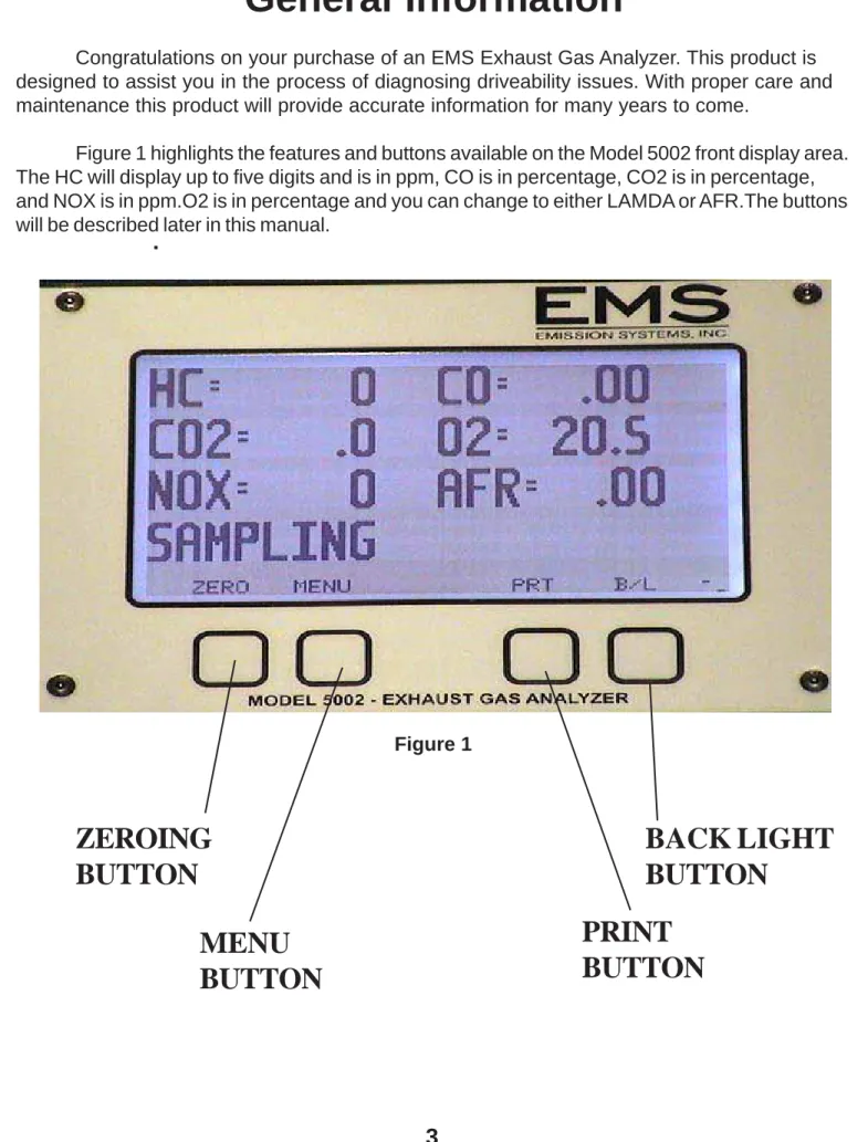
Figure 1 highlights the features and buttons available on the Model 5002 front display area. The HC will display up to five digits and is in ppm, CO is in percentage, CO2 is in percentage, and NOX is in ppm.O2 is in percentage and you can change to either LAMDA or AFR.The buttons will be described later in this manual.
Figure 1
ZEROING
BUTTON
MENU
BUTTON
BACK LIGHT
BUTTON
BUTTON
Button Operation Model 5002
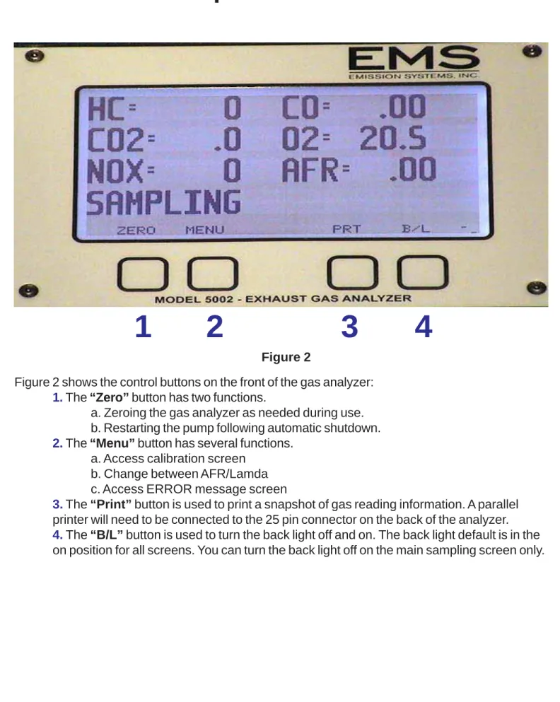
Figure 2 shows the control buttons on the front of the gas analyzer:
1. The “Zero” button has two functions.
a. Zeroing the gas analyzer as needed during use. b. Restarting the pump following automatic shutdown.
2. The “Menu” button has several functions. a. Access calibration screen
b. Change between AFR/Lamda c. Access ERROR message screen
3. The “Print” button is used to print a snapshot of gas reading information. A parallel printer will need to be connected to the 25 pin connector on the back of the analyzer.
4. The “B/L” button is used to turn the back light off and on. The back light default is in the on position for all screens. You can turn the back light off on the main sampling screen only.
Figure 2
Rear Panel Description
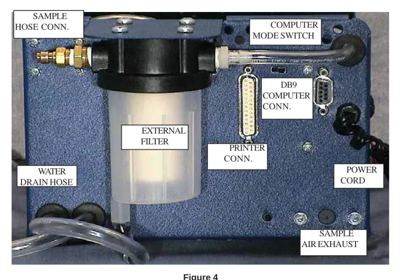
Figure 4 shows the view from the back of the analyzer. The specific details of each item are described below, starting from the upper left corner of the analyzer and working clockwise.
Sample Hose Connection: The sample hose connection uses a quick disconnect coupler. This is helpful for storage of the analyzer and maintenance of the sample hose.
Display Control Switch: The display switch has two basic positions, Computer and Display. The switch should normally be in the right position “Display”. If you are using PC software for display or recording, the switch should be in the left position. Note: The switch direction is based apon you looking at the display. The switch can be changed any time during operation with out turning the power off.
DB9 Computer Connection: This is used to connect the analyzer to your PC/laptop or for the wireless antenna.
Power Cord: Connect to the appropriate voltage supply source.
Sample Air Exhaust: The analyzer discharges the sample air out these ports. Do not plug.
Printer Connection: Connect to an standard parallel printer.
Drain Hose: This hose will drain moisture collected during the sample process.
External Filter: This is the primary sample filter. Filter maintenance will be discussed in the Maintenance section of this manual.
Figure 4 COMPUTER MODE SWITCH SAMPLE HOSE CONN. EXTERNAL FILTER WATER DRAIN HOSE PRINTER CONN. DB9 COMPUTER CONN. POWER CORD SAMPLE AIR EXHAUST
Gas Analyzer Preparation
Getting started is simple. Figure 5 shows the items you should have received in the ship-ping container. Note: This description applies to the Model 5002 analyzer with a display, see Page 16 for instructions on setting up a Model 5002-W & 8000 bluetooth wireless analyzer. The first step is assembling the sample hose. Once the sample hose is assembled,
connect the hose to the sample hose fitting on the back of the analyzer.
Figure 5
The next step is providing power to the analyzer. The analyzer should be connected to a 12v DC power source. You have several options:
1. Cigarette Lighter Connection - Figure 6 (Supplied by EMS)
2. Cigarette lighter to battery connection with adapter - Figure 7(Optional) 3. AC to DC Power Supply - Figure 8 ( 3 AMP min.) Optional)
The Power LED in the lower left corner of the display will light once voltage is applied.
Gas Analyzer Operation
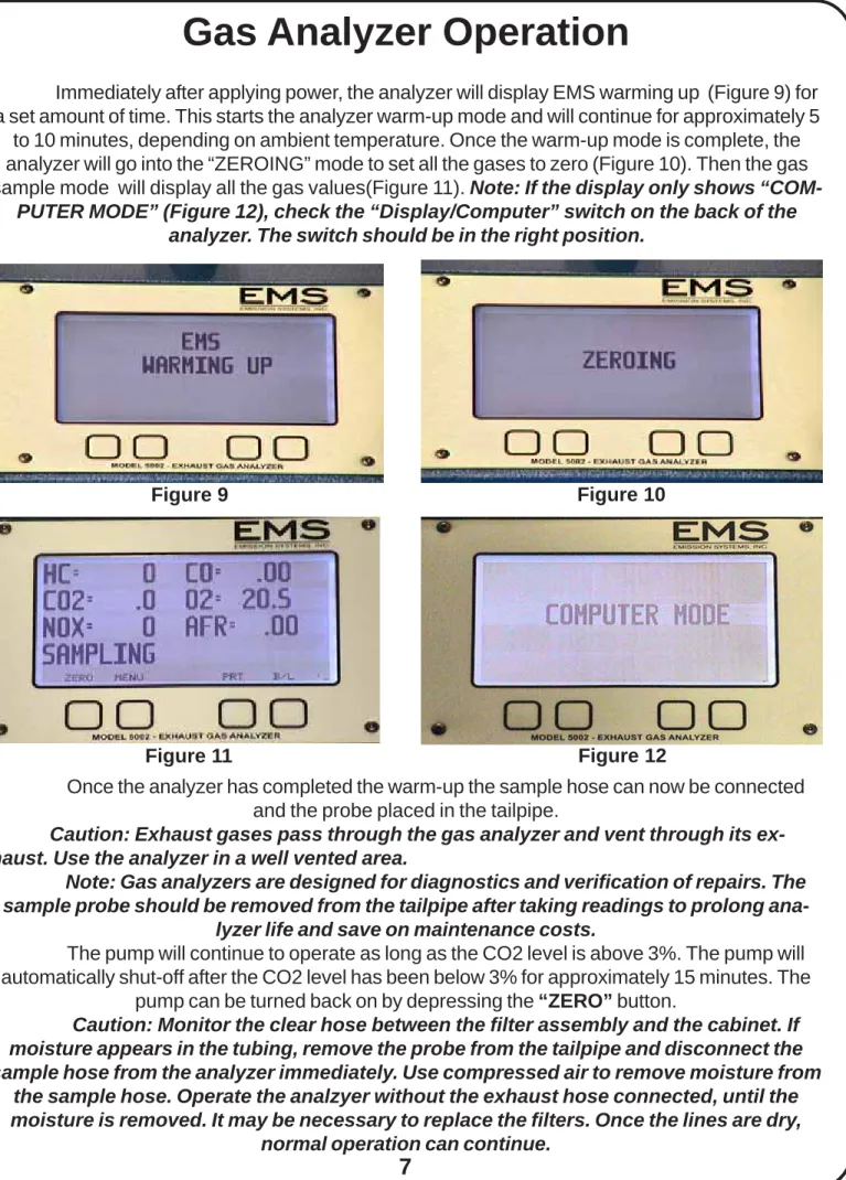
Immediately after applying power, the analyzer will display EMS warming up (Figure 9) for a set amount of time. This starts the analyzer warm-up mode and will continue for approximately 5
to 10 minutes, depending on ambient temperature. Once the warm-up mode is complete, the analyzer will go into the “ZEROING” mode to set all the gases to zero (Figure 10). Then the gas sample mode will display all the gas values(Figure 11). Note: If the display only shows
“COM-PUTER MODE” (Figure 12), check the “Display/Computer” switch on the back of the analyzer. The switch should be in the right position.
Figure 9 Figure 10
Figure 11 Figure 12
Once the analyzer has completed the warm-up the sample hose can now be connected and the probe placed in the tailpipe.
Caution: Exhaust gases pass through the gas analyzer and vent through its ex-haust. Use the analyzer in a well vented area.
Note: Gas analyzers are designed for diagnostics and verification of repairs. The sample probe should be removed from the tailpipe after taking readings to prolong
ana-lyzer life and save on maintenance costs.
The pump will continue to operate as long as the CO2 level is above 3%. The pump will automatically shut-off after the CO2 level has been below 3% for approximately 15 minutes. The
pump can be turned back on by depressing the “ZERO” button.
Caution: Monitor the clear hose between the filter assembly and the cabinet. If moisture appears in the tubing, remove the probe from the tailpipe and disconnect the sample hose from the analyzer immediately. Use compressed air to remove moisture from
the sample hose. Operate the analzyer without the exhaust hose connected, until the moisture is removed. It may be necessary to replace the filters. Once the lines are dry,
Gas Analyzer Operation
Manual Zero: Any time after warm-up, you can zero the gas readings and calibrate O2 by pressing the “ZERO” button (Figure 13). When this operation is being done “ZEROING” will be displayed (Figure 14). The analyzer will shut down automatically if no CO2 is detected after
approx. 15 min. If the pump is off, “STAND BY” will be displayed (Figure 15). Push the “ZERO” key and the pumps will automatically start. Note: The sample probe should be removed from the tailpipe, when the unit is being zeroed.
Automatic Zero: The analyzer will automatically zero as needed. If the analyzer does not sense exhaust gases, the automatic zero procedure will begin. “ZEROING” will be displayed during this process. If exhaust gases are present, the analyzer will wait until the gases are clear.
Figure 16
Low Flow Warning: If gas flow into the bench becomes restricted due to clogged filters or restricted sample hose, the screen will indicate “LOW FLOW” (Figure 16). Check the sample hose for restrictions or kinks. If no problems are found, check the filters. Begin with the External filter and then check the Internal filter. Keep in mind the gas flows through the inside to the outside of the filter. The filter may look clean on the outside, but be clogged on the inside. The best check is to look at the bootom of the external filter. If the LOW FLOW continues to be displayed, the solenoid valve will need to be replaced due to cardon build-up.
Figure 13 Figure 14
Computer Connection: PC software can enhance the diagnostic benefits of the analyzer. The analyzer can be connected to a PC using a 9 pin serial communications cable (DB9). EMS offers software that will display the sample gases, graph data and record information. Using the portable gas analyzer with a laptop will help diagnose problems that only occur when driving. The
EMS software will be discussed later in this manual.
Printing: Connect a parallel printer to the 25 pin connector on the back of the analyzer. Press the “P” button to begin the printing process. The print button prints the gases as displayed when depressed, Figure 17 shows how the gases will be printed. Note: To avoid print communica-tion problems, connect and power on the printer first, then provide power to the analyzer.
Gas Analyzer Operation
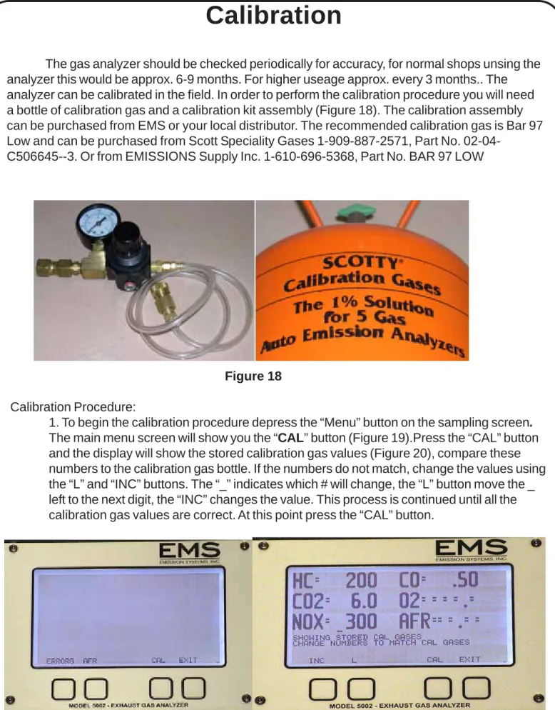
The gas analyzer should be checked periodically for accuracy, for normal shops unsing the analyzer this would be approx. 6-9 months. For higher useage approx. every 3 months.. The analyzer can be calibrated in the field. In order to perform the calibration procedure you will need a bottle of calibration gas and a calibration kit assembly (Figure 18). The calibration assembly can be purchased from EMS or your local distributor. The recommended calibration gas is Bar 97 Low and can be purchased from Scott Speciality Gases 1-909-887-2571, Part No.
02-04-C506645--3. Or from EMISSIONS Supply Inc. 1-610-696-5368, Part No. BAR 97 LOW
Calibration
Figure 18
Calibration Procedure:
1. To begin the calibration procedure depress the “Menu” button on the sampling screen.
The main menu screen will show you the “CAL” button (Figure 19).Press the “CAL” button and the display will show the stored calibration gas values (Figure 20), compare these numbers to the calibration gas bottle. If the numbers do not match, change the values using the “L” and “INC” buttons. The “_” indicates which # will change, the “L” button move the _ left to the next digit, the “INC” changes the value. This process is continued until all the calibration gas values are correct. At this point press the “CAL” button.
Calibration
2. The screen will display “sending cal data” (figure 21).Once the calibration gas values have been sent to the bench,the calibration procedure can continue.
3. The screen will display the gases (Figure 22)and the message to connect the CAl gas. Connect the hose from the regulator assembly to the sample hose inlet. Open the valve on the gas bottle. (Note: Do not adjust the regulator, this was preset to the appropriate flow rate.) Once the calibration gas values stabilize, depress the “CAL” button. The ana-lyzer will capture the gas concentrations and perform the final calibration procedure. The calibration process is now complete.
4. The screen will display a message “ calibration complete” (Figure 23). If the calibration procedure was canceled, the screen will display a message “calibration canceled” (Figure 24), if the calibration was unsuccessful, an error message will be displayed on the main sampling screen. If this occurs, go to the menu screen and errors. one of the gases will show up as “HC or CO or CO2 C Warn”. Go back to the main sampling screen and “ZERO” the unit to clear the error. After either situation, perform the calibration procedure again. If the problem continues, contact EMS or your local distributor
Figure 21 Figure 22
ERROR MESSAGES
If the optical bench detcts any errors during operation, a message will be displayed on the sam-pling screen “SEE ERRORS” (Figure 25). If this message comes up, depress the menu button, and the main menu screen will be displayed (Figure26). Depress the “errors button” and the errors screen will be displayed (Figure 27). At this point you can see any errors being sent from the optical bench. The errors that would possibly be displayed are:
- HC C WARN: This could be a bad calibration or bad optical bench. - CO C WARN: This could be a bad calibration or a bad optical bench. - CO2 C WARN: This could be abad calibration or a bad optical bench. - NOX C WARN: This could be a bad calibration or a bad NOX sensor. - O2 C WARN: This would be a bad O2 sensor.
If an error message does appear and is just bad calibration or something the optical bench detected as not normal, depress the “ZERO” button on the main sampling screen to clear the error. If the error message doesn’t go away, either the bench has an error or is bad or one of the sensors ( O2, NOX) need to be replaced.
Figure 25
Maintenance
Maintenance of the analyzer is essential for accuracy and optimal performance. The filters, hoses and connections should be checked on a regular basis. Maintenance of the gas analyzer is simple and only requires a few minutes, but the time you spend will pay off, with accuracy during the diagnostic process. Specific maintenance procedures are described below:
External Analyzer Maintenance:
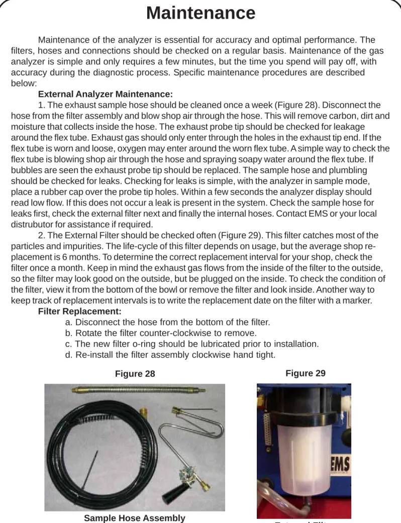
1. The exhaust sample hose should be cleaned once a week (Figure 28). Disconnect the hose from the filter assembly and blow shop air through the hose. This will remove carbon, dirt and moisture that collects inside the hose. The exhaust probe tip should be checked for leakage around the flex tube. Exhaust gas should only enter through the holes in the exhaust tip end. If the flex tube is worn and loose, oxygen may enter around the worn flex tube. A simple way to check the flex tube is blowing shop air through the hose and spraying soapy water around the flex tube. If bubbles are seen the exhaust probe tip should be replaced. The sample hose and plumbling should be checked for leaks. Checking for leaks is simple, with the analyzer in sample mode, place a rubber cap over the probe tip holes. Within a few seconds the analyzer display should read low flow. If this does not occur a leak is present in the system. Check the sample hose for leaks first, check the external filter next and finally the internal hoses. Contact EMS or your local distrubutor for assistance if required.
2. The External Filter should be checked often (Figure 29). This filter catches most of the particles and impurities. The life-cycle of this filter depends on usage, but the average shop re-placement is 6 months. To determine the correct rere-placement interval for your shop, check the filter once a month. Keep in mind the exhaust gas flows from the inside of the filter to the outside, so the filter may look good on the outside, but be plugged on the inside. To check the condition of the filter, view it from the bottom of the bowl or remove the filter and look inside. Another way to keep track of replacement intervals is to write the replacement date on the filter with a marker.
Filter Replacement:
a. Disconnect the hose from the bottom of the filter. b. Rotate the filter counter-clockwise to remove.
c. The new filter o-ring should be lubricated prior to installation. d. Re-install the filter assembly clockwise hand tight.
External Filter Sample Hose Assembly
Maintenance
Internal Analyzer Maintenance:
The maintenance items discussed below are located inside the analyzer. The outside cover will need to be removed to gain access. The cover is held in place with 12 screws, 5 on each side panel and two at the top behind the handle.
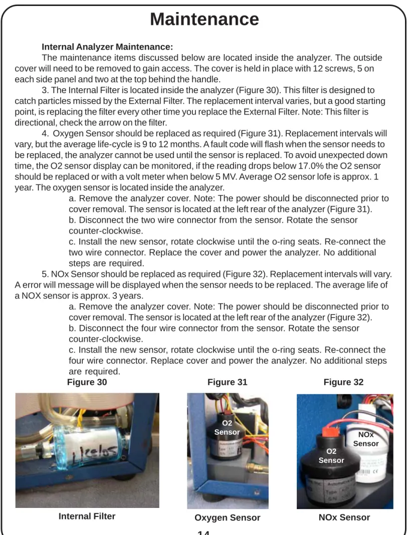
3. The Internal Filter is located inside the analyzer (Figure 30). This filter is designed to catch particles missed by the External Filter. The replacement interval varies, but a good starting point, is replacing the filter every other time you replace the External Filter. Note: This filter is directional, check the arrow on the filter.
4. Oxygen Sensor should be replaced as required (Figure 31). Replacement intervals will vary, but the average life-cycle is 9 to 12 months. A fault code will flash when the sensor needs to be replaced, the analyzer cannot be used until the sensor is replaced. To avoid unexpected down time, the O2 sensor display can be monitored, if the reading drops below 17.0% the O2 sensor should be replaced or with a volt meter when below 5 MV. Average O2 sensor lofe is approx. 1 year. The oxygen sensor is located inside the analyzer.
a. Remove the analyzer cover. Note: The power should be disconnected prior to cover removal. The sensor is located at the left rear of the analyzer (Figure 31). b. Disconnect the two wire connector from the sensor. Rotate the sensor counter-clockwise.
c. Install the new sensor, rotate clockwise until the o-ring seats. Re-connect the two wire connector. Replace the cover and power the analyzer. No additional steps are required.
5. NOx Sensor should be replaced as required (Figure 32). Replacement intervals will vary. A error will message will be displayed when the sensor needs to be replaced. The average life of a NOX sensor is approx. 3 years.
a. Remove the analyzer cover. Note: The power should be disconnected prior to cover removal. The sensor is located at the left rear of the analyzer (Figure 32). b. Disconnect the four wire connector from the sensor. Rotate the sensor counter-clockwise.
c. Install the new sensor, rotate clockwise until the o-ring seats. Re-connect the four wire connector. Replace cover and power the analyzer. No additional steps are required.
Figure 31 Figure 30
Internal Filter Oxygen Sensor
Figure 32 NOx Sensor NOx Sensor O2 Sensor O2 Sensor
Maintenance
Spare Parts and Accessories
Part No:
Description
EMS-5060
Oxygen Sensor
EMS-5065
NOx Sensor
EMS-5093
Internal Filter
EMS-5095
External Filter
EMS-5096
Exhaust Hose
EMS-5097
Exhaust Handle
EMS-5098
Exhaust Tip
EMS-5210
Power Cord
EMS-5500
Gas Calibration Kit
EMS-5020
12V Sample/Water Pump
EMS-5030
12V Solenoid
EMS-5040
Optical Bench
EMS-5050
Flow Switch
EMS-5070
External Filter Head
EMS-5250
Display PC Board
EMS-5200
Front Membrane Switch
EMS-5072
Heavy Duty Water Trap
EMS-5085-K Y-Valve Assembly Kit
EMS-5084-K POP Nut Kit
Wireless Gas Analyzer
The newest feature added to the EMS wireless package is a Bluetooth PC wireless interface
This latest innovation being included by EMS with the wireless package is a virtual USB interface that just requires a simple USB driver being installed on your computer included with the software CD. This wireless interface has a min. range of 30ft. and greater with no obstructions. The USB interface is programmed to communicate with only the wireless antenna supplied with the analyzer to ensure secure communication. Use the EMS windows based software to run live test with graphing, record tests and save them in the data base to be viewed later or printed out.All of the software features can be found in the software manual.
Wireless Gas Analyzer
The lastest innovation from EMS is the Bluetooth wireless gas analyzer. The gas ana-lyzer may be equipped with or without a display. The function of the gas anaana-lyzer is exactly the same. The only difference is the PDA software. The next few pages will describe the PDA software. Note: Download the Palm Software first and then install the EMS Software.
1. The first step is to power-up the gas analyzer and PDA.
2. Figure 1 shows the home screen for most PDA’s. In the center of the screen you will find the Emissions icon. Tap the Emissions icon to launch the software.
3. Figure 2 shows the data display screen. During the warm-up process a note above the Record button shows “Warming up” and just the right you will see a counter. In this example, the warm-up process has 98 seconds remaining. Note: The display control switch at the back of the analyzer must be in the display position.
Figure 1
Model 5001
Model 8000
Wireless Gas Analyzer
4. Figure 3 shows the gas analyzer in sample mode. Tapping the Emissions icon in the upper left hand corner, opens two new menu options. Gas Analyzer (Figure 4) and
Options (Figure 5).
5. The drop down box in (Figure 4) controls the gas analyzer: a. Restart: Tapping this button restarts the gas analyzer.
b. Set Zero: Tapping this button zeros the gas analyzer (Figure 6). c. Calibrate: Tapping this button begins the calibration procedure. d. Pumps Off: Tapping this button turns the gas analyzer pumps off. 6. The drop down box in (Figure 5):
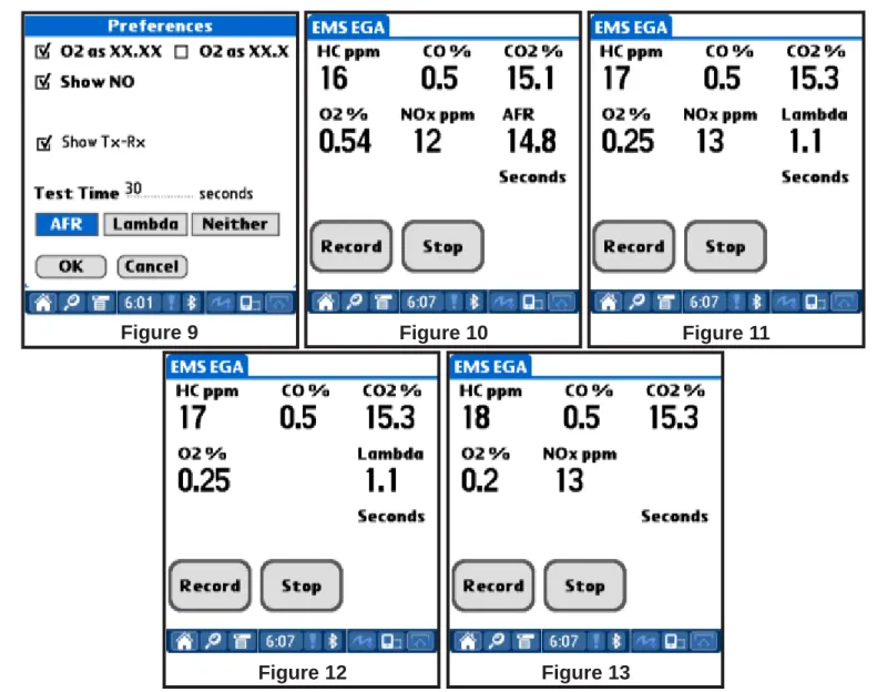
a. Preferences: Tapping this button brings up the display preference screen (Figure 7). This screen allows you to change Test Time, O2 Value, NO Display, AFR/Lambda Display and Transmit/Receive (Tx-Rx) Display. The Tx-Rx shows the communication from the Palm to Analyzer Antenna. Fast switching indicates stronge signal and slow indicates a weak signal.
b. About wGas: Tapping this button provides information about the software version (Figure 8).
Figure 3 Figure 4 Figure 5
Wireless Gas Analyzer
7. Figure 9 shows the Preferences screen. Figures 10-13 demonstrate changes made to the display Preferences:
a. O2 as XX.XX and O2 as XX.X: Figure 10 shows O2% displayed with two decimal point resolution for maximum accuracy. Figure 13 shows O2% displayed with one decimal point resolution.
b. Show NO: Figure 10 shows NOx displayed in ppm. In Figure 12 NOx is not displayed.
c. Test Time: The recording time can be adjusted in this box. Figure 9 shows the current time set to 30 seconds.
d. AFR, Lambda and Neither: This changes the desired air/fuel calculations. Figure 10 displays AFR (Air/Fuel Ratio), Figure 11 displays Lambda and Figure 13 shows Neither.
e. Show Tx-Rx: This shows the communication strength between the Palm and Analyzer Antenna.
Figure 9 Figure 10 Figure 11
Wireless Gas Analyzer
8. This section will explain recording a test and transferring the data to the PC. Figure 14 shows a sample Test recording.
a. To record a test, set the Test Time in the Preferences screen to the desired recording length in seconds.
b. Insert the sample hose into the tailpipe. Once the gases begin to display, tap the record button on the sample display screen lower left. The top of the sample screen will show Test 1 of 1 and a Seconds counter will begin. The recording will stop once the Test Time has expired or when the Stop button is tapped. Addi-tional tests may be captured by tapping the Record button. The title at the top of the screen will change from Test 1 of 1 to Test 2 of 2.
c. To transfer the tests, insert the Palm into the Palm cradle and HotSync to the PC. After the HotSync is complete, open the EMS Database Software. Select Find Owner/Vehicle button. The next screen will display all the available Tests that have been saved into the database. The most recent tests can be identified by looking at the date. Note: the test date will be the date the HotSync was performed. Once this is opened it will show the total number of tests made with a test number. At this point the tests can be opened or saved to the database as a particular Name, Vehicle, File, etc.
Wireless Analyzer Messages
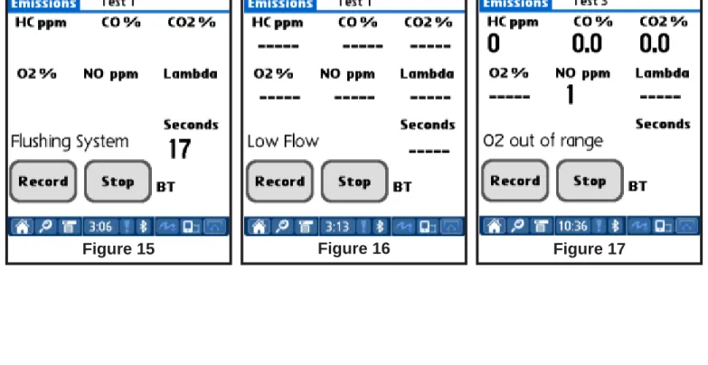
Figure 16
Figure 15 Figure 17
9. The gas analyzer displays various messages through the Palm screen. The mes-sages may indicate normal system operation, faults or analyzer maintenance.
a. Figure 15 - Flushing System Message: The Flushing System message dis-plays under two conditions. 1) If the pump is operating and the CO2% reading drops below 3.0% for a set period of time, the gas analyzer will begin a system flushing procedure. 2) The Flushing System message will appear as part of a Zeroing procedure.
b. Figure 16 - Low Flow: The Low Flow message appears when the volume of air flow through the gas analyzer is low. This message will appear if the sample hose is kinked/restricted or if the filters are clogged.
c. Figure 17 - O2 out of range: The O2 out of range message will appear when the O2 sensor reading is out of specification. Normal O2 sensor readings should be approximately 21%, with the pump running, sampling ambient air. To avoid unexpected down time, the O2 sensor display can be monitored, if the reading drops below 17.0% the O2 sensor should be replaced.
Gas Analyzer Usage
Exhaust gas analyzers can be used to diagnose driveability concerns, ignition system problems, fuel management issues, engine mechanical problems, excessive emissions prob-lems and many other vehicle systems. Vehicle inspection and preparation are the keys to getting the most out of your gas analyzer.
1. A visual inspection should include; vacuum hoses, air filter, exhaust system, air management system, emission related components, etc. If the malfunction indicator light (MIL) is illuminated, check the diagnostic trouble codes (DTC’s) prior to testing.
2. Vehicle preparation:
a. The engine should be at operating temperature prior to testing.
b. Start the engine and run until the cooling fan cycles on and off. Another option is using a scan tool to check the engine coolant temperature
(ECT). The temperature should exceed 190 degree F.
c. After the engine is warm, increase the engine speed to 2500 RPM for approximately 60 seconds.
d. Return the engine speed to idle.
e. Insert the sample probe and begin your diagnostics.
Understanding the relationship of exhaust gases will enhance your ability to diagnose driveability issues. The Exhaust Gas Relationship Chart will provide a few suggestions:
Hydrocarbons Carbon Monoxide Oxygen Carbon Dioxide HC (PPM) CO (% ) O2 (% ) CO2 (% )
Normal combustion efficiency Low Low Low High
Engine Mechanical Issues High Low High Low
Cooling System Issue-Cold Engine High High Low Low
Ignition misfire, false air, lean condition High Low High Low
Rich mixture Slightly High High Low Low
Rich mixture with ignition misfire condition High High High Low
Exhaust leak and air injection issues Low Low High Low
Lean mixture High Low High Low
Exhaust Gas Relationship Chart
Potential Problems
Exhaust gas analyzers can be used to diagnose other vehicle systems. Here are a few suggestions:
1. Evaporative emission system operation. 2. Evaporative emission system leaks. 3. Fuel oders in and around the vehicle. 4. No-Start conditions.
5. Engine combustion gases in the cooling system. 6. Air injection emission systems.
7. Exhaust system leaks. 8. More...
Warranty
• Emission Systems products are guaranteed to be free of defects in material
and workmanship to the original purchaser, for a period of
one year
from the
date of purchase. Probes and electrical leads are warranted for ninety days. The
optical bench is warranted for
18 Months
.
• This warranty does not apply to products which have been:
1) Altered
2) Improperly installed, maintained or repaired.
3) Damaged by accident, negligence or misuse.
• THIS WARRANTY EXCLUDES ALL INCIDENTAL OR
CONSEQUEN-TIAL DAMAGES
• If you suspect there is a problem with your unit, the operating manual should be
reviewed first. Your particular problem may be covered in the operating
instruc-tions. If the issue cannot be resolved, contact EMS or your authorized distributor
for additional information. If the unit requires repair, contact EMS to obtain a
Return Authorization Number. The unit should be properly packaged and should
include all accessories. The unit will be returned in the shortest possible
timeframe.
• In the USA and Canada call: 847-854-8483 for assistance.
• Outside USA call your authorized distributor for assistance.
Warranty Information:
• Date of Purchase: ____________
• Serial Number: ______________