steel
By
Mohanad Alabdullah
BSc, MSc of Eng.
Submitted in fulfilment of the requirements for the degree of
Doctor of Philosophy
School of Engineering
Deakin University
and geometry response on machinability during turning AL-6XN super austenitic stainless steel: A work hardening and wear studies on AL-6XN alloy.
Materialwissenschaft und Werkstofftechnik, 2017. 48(3-4): p. 190-197.
2. Alabdullah, M., et al., Effect of Microstructure on Chip Formation during Machining of Super Austenitic Stainless Steel. International Journal of Materials Forming and Machining Processes 2017. 4(1): p. 1-18.
3. Alabdullah, M., et al., Experimental and finite element analysis of machinability of AL-6XN super austenitic stainless steel. The International Journal of Advanced Manufacturing Technology, 2016. 91(1): p. 501-516.
4. Alabdullah, M., A. Polishetty, and G. Littlefair, Impacts of Wear and Geometry Response of the Cutting Tool on Machinability of Super Austenitic Stainless Steel.
International Journal of Manufacturing Engineering, 2016: p. 1-9.
5. Alabdullah, M., A. Polishetty, and G. Littlefair, Microstructural and Surface Texture Analysis due to Machining in Super Austenitic Stainless Steel. Journal of Metallurgy, 2016: p. 1-8.
Firstly, I would like to acknowledge my principal supervisor, Dr Ashwin Polishetty,
for his support and encouragement during my PhD study. Dr Ashwin always inspired me with through his enthusiasm, scientific knowledge, and guidance. His encouragement was instrumental in the completion of this research and the associated writing of the thesis.
I would also like to thank Dr Junior Nomani, Dr Moshe Goldberg andProfessor Guy Littlefair for their enormous efforts that assisted me through my PhD study to this stage.
Special thanks to my wife, the love of my life, Samar AL-Najafi for her patience and support. She has been the source of motivation at every moment through my married life and studies required to complete the PhD.
Lastly, I will always be grateful to my parents for their logistic assistance that have improved my spirits at this stage of my life. I will never forget the unique inspiration given to me by my parents who always pray for me and help me in every possible way.
i
1
Introduction ... 1
1.1
Background of the research ... 1
1.2
Thesis objectives ... 2
1.3
Thesis layout ... 3
2
Literature review ... 7
2.1
Introduction to austenite and super austenitic stainless steel alloys . 7
2.1.1 History and metallurgical aspects of the AL-6XN alloy ... 82.1.2 Material properties and applications ... 10
2.2
Machining and machinability of materials ... 11
2.2.1 Machinability aspects ... 12
Cutting forces analysis ... 12
Chip formation ... 14
Work hardening measurements ... 20
Metallography analysis ... 22
Tool wear analysis ... 25
Surface roughness measurements ... 26
2.3
Introduction to milling ... 27
2.4
Introduction to turning ... 29
2.5
Research on the machinability of stainless steel alloys ... 30
2.6
Thermomechanical analysis in the cutting shear zone ... 36
2.7
Finite element analysis in metal cutting ... 38
2.7.1 Modelling ... 39
2.7.2 Main techniques in describing the FEA setup in metal cutting ... 39
ii
2.9
Summary ... 44
3
Experimental design ... 46
3.1
Material characterization ... 47
3.1.1 Material chemical composition ... 47
3.1.2 Tensile test ... 48
3.1.3 Hardness test of the bulk material ... 49
3.1.4 Microstructure and phases characterization of the bulk material ... 49
3.2
Machinability characterization of AL-6XN alloy ... 51
3.2.1 Cutting forces analysis ... 53
3.2.2 Chip morphology ... 54
3.2.3 Work hardening measurements in the machined surfaces ... 55
3.2.4 Metallography analysis of the work hardened layer ... 57
3.2.5 Tool wear analysis ... 58
3.2.6 Surface texture analysis ... 58
Surface roughness measurement using optical profilometer ... 59
Inspection of the machined surfaces using SEM ... 61
3.3
Machinability assessment of AL-6XN and AISI 316 alloys ... 62
3.4
Chip formation study in machining AL-6XN alloy ... 65
3.4.1 Quick stop approach setup ... 66
3.4.2 Collection & preparation of the chip root samples for SEM and EBSD analysis ... 66
3.4.3 Strain measurements in the frozen chip root samples ... 68
3.4.4 Work hardening evaluation in the frozen chip root samples ... 68
3.4.5 Temperature measurements in turning AL-6XN alloy ... 68
iii
3.5.2 Model selection, material properties and boundary conditions ... 72
3.5.3 Residual stresses by FEA ... 76
3.5.4 FEA machining assessment study of AL-6XN and 316 alloys ... 76
4
Results, analysis and discussion ... 80
4.1
Material characterization ... 80
4.1.1 Tensile test ... 80
4.1.2 Hardness measurements ... 82
4.1.3 Microstructure and phases characterization ... 82
4.2
Machinability characterization of AL-6XN alloy ... 83
4.2.1 Cutting forces ... 83
Effects of the cutting parameters on the cutting forces value ... 87
Change in the cutting forces value regards to the applied cutting parameters 89 4.2.2 Chip morphology ... 91
4.2.3 Work hardening measurements in the machined surfaces ... 96
4.2.4 Metallography analysis of the work hardened layer ... 98
4.2.5 Tool wear analysis ... 99
4.2.6 Surface texture analysis ... 104
Surface roughness measurement using optical profilometer ... 104
Inspection of the machined surfaces using SEM ... 107
4.2.7 Effects of tool wear on the cutting forces ... 110
4.2.8 Effects of tool wear on surface roughness ... 112
4.3
Machinability assessment of AL-6XN and AISI 316 alloys ... 114
4.3.1 Cutting forces analysis ... 114
Effects of the cutting parameters on the cutting forces of AL-6XN and 316 alloys ... 117
iv
4.3.4 Tool wear analysis using Alicona InfiniteFocus profilometer ... 128
4.4
Chip formation study in machining of the AL-6XN alloy ... 135
4.4.1 Microstructure analysis ... 135
4.4.2 Strain measurements in the frozen chip root samples ... 139
4.4.3 Work hardening measurements in the frozen chip root samples ... 141
4.4.4 Temperature measurements in turning AL-6XN alloy ... 142
4.4.5 Tool wear investigation in the chip formation study ... 143
4.5
FEA of machinability of AL-6XN alloy ... 147
4.5.1 Microstructure analysis ... 147
4.5.2 Stress and strain measurements ... 148
4.5.3 Temperature measurements ... 151
4.5.4 Residual stresses measurements by FEA ... 152
4.5.5 Model validation ... 154
4.5.6 FEA machining assessment study for AL-6XN and AISI 316 alloys ... 156
Stress and strain analysis ... 156
FEA residual stresses of the AL-6XN and AISI 316 alloys for the assessment process ... 160
Correlation between the residual stresses and the work hardening tendency at the machined surfaces ... 162
4.6
Summary ... 163
5
Conclusions ... 169
5.1
Material characterisation ... 169
5.2
Machinability characterisation of AL-6XN alloy ... 169
v
5.5
FEA of machinability of AL-6XN alloy ... 175
5.6
FE model validation ... 176
5.7
Contribution towards manufacturing industry and machining
literature ... 177
6
Thesis work limitations and recommendations for future
work ... 179
6.1
Limitations to the present thesis work ... 179
6.2
Recommendations for future work ... 180
Bibliography ... 183
Appendix ... 206
A.
Machinability characterization of AL-6XN alloy ... 206
B.
Machinability assessment of AL-6XN and AISI 316 alloys ... 222
C.
Chip formation study in machining of the AL-6XN alloy ... 231
vi
Figure 2.1 Typical cutting forces components in Merchant circle ... 13
Figure 2.2 Orthogonal metal cutting model [36] ... 15
Figure 2.3 Chips formation diagram ... 15
Figure 2.4 Types of chips ... 16
Figure 2.5 Vickers indentation geometry [57] ... 21
Figure 2.6 Iron-carbon equilibrium diagram ... 23
Figure 2.7 Formation of the roughness concaves and conveys on the machined surface ... 26
Figure 2.8 Milling operation [82] ... 28
Figure 2.9 Typical cutting force curve per one cutter revolution in milling ... 28
Figure 2.10 Turning operation [86] ... 29
Figure 2.11 Typical cutting force curve per one cutter revolution in turning ... 30
Figure 2.12 Elements and nodes in a FE meshed part ... 38
Figure 2.13 Proposed models [67], A- Eulerian B- Lagrangian ... 41
Figure 3.1 AL-6XN alloy sample used to reveal the chemical composition ... 47
Figure 3.2 Tensile test sample ... 48
Figure 3.3 Tensile test experimental setup ... 48
Figure 3.4 Electrolytic etching experimental setup ... 50
Figure 3.5 Sample preparation for the electrolytic experiment ... 50
Figure 3.6 Machining experimental setup ... 52
Figure 3.7 Dimensions and geometries of milling cutter (cutting tool) ... 52
Figure 3.8 Cutting tool holder ... 53
Figure 3.9 kistler multichannel charge amplifier device ... 53
Figure 3.10 Cutting forces components ... 54
vii
Figure 3.13 Extracting the machined samples cross-sections ... 56
Figure 3.14 Estimation of the positions for the microhardness measurements in the work hardened layer ... 57
Figure 3.15 Three selected positions to calculate the surface roughness values ... 59
Figure 3.16 Alicona InfiniteFocus profilometer ... 59
Figure 3.17 Roughness measurement direction, A- Longitudinal, B- Lateral ... 61
Figure 3.18 Representation of the scanned machined surface by the AIF optical lens, A- 3D view, B- 2D view, C- Roughness values for a given path length ... 61
Figure 3.19 Cutting tool edges and the dragged path to calculate the output profile ... 65
Figure 3.20 Mounted quick-stop device on the lath machine ... 65
Figure 3.21 Extraction of the formed chip root, A- Frozen chip, B- Cutting of the frozen chips, C- Metallography prepared chip root samples ... 67
Figure 3.22 HKL Channel 5 software ... 67
Figure 3.23 Setup of the infrared thermal camera ... 69
Figure 3.24 Modelling the real microstructure of the AL-6XN alloy, Microstructure EBSD band contrast map (on the left), Meshed real microstructure (on the right) ... 71
Figure 3.25 FEA model setup ... 72
Figure 3.26 Stress-strain curves for the experimental, original and modified JC parameters... 74
Figure 3.27 Residual stresses measurements ... 76
Figure 3.28 Workpiece and cutting tool setup ... 77
Figure 3.29 True stress-strain curves for the original and calibrated JC parameters ... 79
Figure 4.1 Tensile test samples ... 81
Figure 4.2 Microstructure of the AL-6XN alloy electrolyticaly etched and revealed under optical microscope ... 82
Figure 4.3 The machined workpiece of the AL-6XN alloy ... 83
viii
Figure 4.7 Effect of cutting parameters on cutting forces (Fy) and (Fx) value ... 88
Figure 4.8 Δ change in cutting forces value regards the applied cutting parameters ... 90
Figure 4.9 Chips of the eight cutting trials as collected after machining process ... 91
Figure 4.10 SEM images of the chips free surfaces... 92
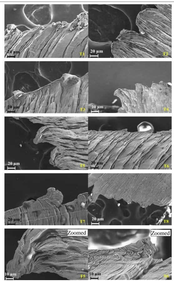
Figure 4.11 SEM images of the serreated edges of the chips, and zoomed images for the edges of trials (T5) and (T6) ... 93
Figure 4.12 AsB image of the chip cross section to reveal the shear bands ... 95
Figure 4.13 Polished chip cross section ... 95
Figure 4.14 AL-6XN alloy serration degree measured at the eight cutting trials ... 96
Figure 4.15 Microhardness values in the work hardened layers of the polished samples extracted from the eight cutting trials ... 97
Figure 4.16 A- Microstructure of the AL-6XN under SEM detector, B- Microstructure of the cross section of the machined samlple, C- band contrast BC map of the cross section of the machined sample, D- EBSD image of the cross section of the machined sample ... 99
Figure 4.17 SEM images of the BUE formed on the cutting edge used at trial (T5) ... 100
Figure 4.18 SEM images of the BUE formed on the cutting edge used at trial (T7) ... 100
Figure 4.19 A- Inspection of the microstructure of the formed BUE in trial (T7), B- Inspection of the formed chip of trial (T7) to make a comparison with the microstructure of the BUE ... 101
Figure 4.20 SEM images of the cutting insert of trial (T6) to reveal wear types ... 101
Figure 4.21 Adhered particles on the chip cross sction ... 102
Figure 4.22 SEM images of the eight cutting tools ... 103
Figure 4.23 Crater wear CW length and depth of the eight cutting tools ... 104
Figure 4.24 Surface roughness measurements at the three selected positions ... 105
Figure 4.25 Distortion analysis for the microstructure of the machined surfaces of trials (T1) and (T4) using SEM, A- Trial (T1) at position 1, B- Trial (T4) at position 1, C- Trial (T1) at position 2, D- Trial (T4) at position 2, E- Trial (T1) at position 3, F- Trial (T4) at position 3 ... 108
ix
(T8) at position 2, E- Trial (T5) at position 3, F- Trial (T8) at position 3 ... 109
Figure 4.27 Effects of tool wear types on the cutting forces value ... 111
Figure 4.28 Effects of tool wear types on surface roughness ... 112
Figure 4.29 Feed forces (unprocessed signals) of AL-6XN and 316 austenite stainless steel ... 114
Figure 4.30 Mean values of the cutting forces during cutting AL-6XN and 316 austenite stainless steel, A- Normal force (Fx), B- Feed force (Fy) ... 115
Figure 4.31 Tensile strength of AL-6XN and 316 alloys ... 116
Figure 4.32 Percentage difference (increase) in the cutting forces of the AL-6XN compared to 316 austenite stainless steel ... 117
Figure 4.33 Effects of the cutting parameters on the feed (Fy) and normal (Fx) forces, A- Effects of feed rate, B- Effects of the cutting speed, C- Effects of the depth of cut ... 119
Figure 4.34 Electrolytically etched microstructures, A- AL-6XN alloy, B- 316 alloy ... 121
Figure 4.35 Work hardening due to machining, A- AL-6XN, B- 316 alloys ... 122
Figure 4.36 Percentage increase of the work hardening tendency measured at 5 µm beneath the machined surfaces of AL-6XN and 316 alloys ... 124
Figure 4.37 Roughness values of the machined AL-6XN and 316 alloys, A- Positions 1, B- Position 2, C- Position 3 ... 125
Figure 4.38 Penetration normal forces (Fx) recorded at trials (T1) and (T8) at the beginning of the cutting process for AL-6XN and 316 alloys ... 126
Figure 4.39 Δ% in the surface roughness values of the AL-6XN alloy with reference to the surface roughness values of the 316 alloy measured at three selected positions on the machined surfaces .. 127
Figure 4.40 Cutting tool path profile estimation of the new and worn edges (toole nose) for the AL-6XN alloy ... 130
Figure 4.41 Cutting tool path profile estimation of the worn edges (toole nose) for the 316 alloy .... 132
Figure 4.42 The microstructure of the frozen chips root, A- Chip root formed at 65 m/min, B- Stagnation zone of the chip root at 65 m/min, C- Chip root formed at 94 m/min, D- Stagnation zone of the chip root at 94 m/min ... 136
x
10° and HAGBs (blue) > 10° ... 137 Figure 4.44 Slip lines formation model within the grain ... 138 Figure 4.45 Plastic strain map for Vc = 65 m/min, A- At the chip root sample, B- At the stagnation zone ... 139 Figure 4.46 Plastic strain map for Vc = 94 m/min, A- At the chip root sample, B- At the stagnation zone ... 139 Figure 4.47 Strain values at measured at 65 m/min, I- Stagnation zone, II- Hardened layer beneath the machined surface, III- Primary shear zone, IV- Chip region ... 140 Figure 4.48 Strain values at measured at 94 m/min, I- Stagnation zone, II- Hardened layer beneath the machined surface, III- Primary shear zone, IV- Chip region ... 140 Figure 4.49 Work hrdening map within the microstructure of the frozen chip root samples fabricated at Vc = 65 m/min (on the left), Vc = 94 m/min (on the right) ... 141 Figure 4.50 Temperature measurements ... 143 Figure 4.51 Cutting tool edges scanned under SEM detector for a Vc = 65 m/min, A- Notch wear, chipping and BUE formation, B- Micro cracks propagation and BUE formation, C- BUE deposition on the cutting edge ... 144 Figure 4.52 Cutting tool edges scanned under SEM detector for Vc = 94 m/min, A- Flake wear, micro cracks propagation, pitting area and BUE formation, B- BUE deposition ... 145 Figure 4.53 Surface profile form measurements applied on worn cutting edge at Vc = 94 m/min (on the left) and worn cutting edge at Vc = 65 m/min (on the right) ... 146 Figure 4.54 Profile curves obtained at various positions, A- New cutting edge, B- Worn cutting edge at Vc = 94 m/min, C- Worn cutting edge at Vc = 65 m/min ... 147 Figure 4.55 A- Microstructure deformation and Von Mises stress (Pa) distribution during the cutting process, B- Crack initiation and propagation along the primary shear zone, C- The formation of the first chip shows the shear band and primary shear zone ... 148 Figure 4.56 Observation of the formed chip during the cutting process at Vc = 65 m/min, A, B- Von Mises stresses (Pa), C, D- Equivalent plastic strain mm/mm ... 149 Figure 4.57 Stress and strain distribution through the grains of the entire model at the beginning of the cutting process, A- Von Mises stress (MPa) at Vc = 94 m/min, B- PEEQ equivalent plastic strain
xi
Figure 4.58 A- Maximum stress and strain obtained from the FEA modelling at Vc = 65 and 94 m/min, B- Comparison between the experimental and FE strain values ... 151 Figure 4.59 Temperature measurements (°C) during simulation of the cutting process at Vc = 65 m/min, A- At the beginning of the cutting process, B- After forming the chips ... 152 Figure 4.60 Experimental and FEA results of the measured temperature (°C), A- At the beginning of the cutting process, B- After 20 seconds of the cutting process, LCS = low cutting speed, HCS = high cutting speed ... 152 Figure 4.61 Residual stresses (S11) MPa, A- For Vc = 94 m/min, B- For Vc = 65 m/min, C- Heat distribution that affects the tensile residual stress ... 153 Figure 4.62 Obtained errors during validating the FE model ... 154 Figure 4.63 Shear plane angle measurements at Vc = 94 m/min, A- Experimentally, B- From the FEA model ... 155 Figure 4.64 Von Mises stress and equivalent plastic strain PEEQ distributions in the machined 316 and AL-6XN alloys, A, B, C& D- PEEQ strain and Von Mises stress at the beginning and at the maximum for the 316 alloy, E, F,G& H- PEEQ strain and Von Mises stress at the beginning and at the maximum for the AL-6XN alloy... 157 Figure 4.65 Von Mises stress and PEEQ strain graphs of the AL-6XN and 316 alloys at the beginning of the cutting process, A&C- Values measured at Vc = 65 m/min, B&D- Values measured at Vc = 94 m/min ... 158 Figure 4.66 Measurements of the residual stresses S11 from the machined surface down to the bottom of the workpiece, A- At Vc = 65 m/min, B- At Vc = 94 m/min ... 160 Figure 4.67 Δ% in the FEA machining results between the AL-6XN and 316 alloys ... 162 Figure 4.68 Correlation between the residual tensile stress and work hardening tendency ... 163
xii
Table 2.2 AL-6XN alloy typical chemical composition ... 9
Table 3.1 Chemical composition of the as received AL-6XN alloy... 48
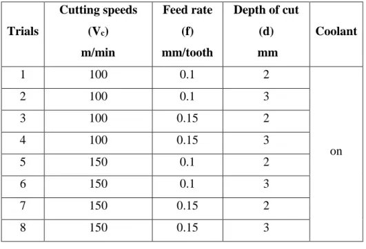
Table 3.2 Arrangement of the cutting trials to machine the AL-6XN alloy ... 51
Table 3.3 AIF technical specifications ... 60
Table 3.4 AL-6XN and 316 Alloys chemical compositions ... 62
Table 3.5 Designation of the cutting trials to machine the 316 alloy ... 63
Table 3.6 Arrangement of the cutting trials for the chip formation study ... 66
Table 3.7 The inputs values used in the TIM connect software ... 69
Table 3.8 Johnson Cook model constants for the AL6XN alloy ... 74
Table 3.9 Tensile test parameters ... 74
Table 3.10 Physical properties of the AL6XN ... 75
Table 3.11 Cutting tool physical properties as supplied by the manufacturer ... 75
Table 3.12 Mechaical properties of the 316 workpiece and the cutting tool ... 78
Table 3.13 Original and calibrated Johnson Cook paramters of 316 and AL-6XN alloys ... 78
Table 4.1 AL-6XN tensile test results ... 81
Table 4.2 AL-6XN alloy bulk hardness ... 82
Table 4.3 Changes in roughness Ra relating to the applied cutting parameters at positions 1, 2, and 3 ... 106
Table 4.4 Residual stresses assessment given by FEA ... 161
xiii
Symbols Description Unit
A Yield stress MPa
A0 Area of undeformed grain µm2
Af Area of deformed grain µm2
B Stress hardening MPa
C Strain rate sensitivity coefficient -
d Depth of cut mm
D Damage factor -
f Feed rate mm/tooth
Fc Feed force N
Ft Normal force N
Fx Normal force in milling N
Fy Feed force in milling N
H Serration degree -
hmax Chip peak thickness mm
hmin Chip valley thickness mm
m Thermal coefficient -
n Hardening coefficient -
Ra Arithmetic mean roughness µm
xiv
tc Formed chip thickness mm
TM Melting temperature °C
Ttr Ambient temperature °C
Vc Cutting speed m/min
β Fiction angle Degree
γ Rake angle Degree
τ Shear strain mm/mm
ϕ Shear plane angle Degree
𝜀0˙ Reference strain rate s-1
𝜀𝑒˙𝑝𝑙 Equivalent plastic strain rate s-1
𝜀𝑒𝑝𝑙 Plastic strain mm/mm
Abbreviations Description
AIF Alicona InfiniteFocus ASS Austenite stainless steel
BUE Built up edge
CW Crater wear
EBSD Electron backscatter diffraction FEA Finite element analysis
xv HAGB High angle grain boundaries LAGB Low angle grain boundaries
OOF2 Object-oriented finite element analysis OPS Oxid polishing suspension
PEEQ Equivalent plastic strain SASS Super austenitic stainless steel SE2 Secondary electron detector SEM Scanning electron microscope SSS Steady state stage
xvi
This thesis presents an investigation into the machinability of the super austenitic stainless steel, AL-6XN alloy. The machinability of a material is defined as the ease of material removal by the edge of the cutting tool using one of the common machining operations (milling, drilling or turning) to produce a satisfactory surface quality at low cost. The AL-6XN alloy has recently replaced the conventional austenite stainless steel alloys and is being used in the oil and gas industry (oil and gas pipelines, pipe fittings and valves), offshore structures, chemical and food-processing systems, nuclear power plants, pumps and electrical transforms cases that are used in harsh environments. The current literature regarding machining does not explain the AL-6XN alloy plastic behaviour when the alloy is being machined using traditional machining operations. Due to using the AL-6XN alloy in the abovementioned sensitive applications, it is disappointing to have a failure in a machined component, during its lifespan, due to improper machining procedure. Therefore, the current work attempts to fill the gap in the literature regarding machining of the AL-6XN alloy. The research in this thesis consists of three main stages.
The first stage in this thesis consists of two parts:
• In the first part of this stage, observational cutting trials were conducted to determine the machining behaviour of the AL-6XN alloy. Milling trials were carried out and the machining aspects, such as cutting forces, chip morphology, work hardening, microstructure analysis, tool wear and surface roughness, were investigated. Machining issues that were noted include: high feed and normal forces; extreme work hardening tendency; low quality of the machined surfaces; built-up edge formation; high degree of serration of the formed chips, flank, crater and chipping wear of the cutting tools.
• The second part of this stage included the assessment of the machinability of the AL-6XN alloy. Milling trials were also conducted on a difficult-to-machine alloy (AISI 316 austenite stainless steel) using the same cutting parameters and cutting environment that was used to machine the AL-6XN alloy in the first part above. The cutting forces analysis, roughness of the machined surfaces, work hardening tendency and the geometry of the worn tools were assessed.
xvii
calculated through this finite element study and a comparison was made on the gained results to assess the simulated cutting process of both alloys. Overall, the experimental and the finite element results demonstrated that the machinability of the AL-6XN alloy was inferior than the AISI 316 alloy.
In the second stage of this thesis, chip formation was studied when the frozen chip root samples were generated by interrupting the turning process using the quick stop method. Electron backscatter diffraction and secondary electron images of high quality polished and electrolytically etched chip root samples revealed the plastic deformation ahead of the cutting tool tip, in the work hardened layer and in the chip region. Micro-cracks, which perform as built-up edge initiators, were identified in the stagnation zone of the frozen chip root samples. In addition, in this stage, the plastic strain map was calculated based on the change in the size of the deformed grains. A work hardening map was estimated in the stagnation zone, the deformed and sub-deformed layers and in the chip region. The results revealed a high plastic strain of 6.5 and 5.7 mm/mm when cutting speeds of 94 and 65 m/min, respectively, were applied. In addition, the microhardness values were significantly increased by up to more than double that of the base material in the shear zones and reached the maximum values in the chip region.
The third stage of this thesis describes the development of a 2-dimensional finite element model to illustrate the cutting process of the AL-6XN alloy. The AL-6XN alloy microstructure was scanned using electron backscatter diffraction and then the microstructure was analysed using Object-Oriented Finite element analysis software to create a meshed microstructure. The meshed microstructure was imported and used in ABAQUS software to build the finite element model in order to acquire precise results through the grains and at the grain boundaries of the AL-6XN alloy microstructure. The Johnson-Cook constitutive model was used and calibrated to present the alloy plastic behaviour under high strain rate deformation processes, such as machining. The proposed model was used to predict the stresses, strains, temperatures, residual stresses and chip morphologies based on the real (physical) microstructure. The results from the model were verified by the results of the experimental work and the overall recorded errors were less than 7.5%.
xviii
alloy to the academic community. Secondly, the benefits of the output data are useful for manufacturers when producing new or replacement machined components using the AL-6XN alloy. Lastly, a finite element model that simulates chip formation while machining the AL-6XN alloy has been established for the first time. Due to the satisfactory results, this model can be utilised to expect the plastic behaviour of the AL-6XN alloy during the cutting process using boundary conditions consisting of various cutting parameters.
1
1
Introduction
1.1
Background of the research
Industrial needs, and scientific and technological challenges impose on manufacturers the need to better develop existing materials or even produce new materials that have superior properties at low cost. It is a fact that components made of these developed materials are efficient in overcoming common industrial issues such as corrosion and failure at elevated temperatures due to their improved strength. However, many of those manufactured components have suffered instant failure (short lifespan) in industrial use due to improper manufacturing processes that have resulted in poor surface finish and quality. In the 19th century, most manufacturers used a trial and error
procedure to determine the optimal components with the longest lifespan [1]. This old procedure required manufacturers to spend extra funds on wasted materials and worn cutting tools. Additionally, the wasted materials were considered harmful, unwanted and inversely impacted the environment. The current, rapid development in technology, especially in the manufacturing and machining fields, assists researchers to apply various tests to evaluate the machinability of materials, regardless of their superior mechanical properties, within professional machining laboratories. These machinability evaluation tests are economical as they are conducted using small samples of the tested materials which reduce waste, cost and environmental damage. In addition, the developed technology in the manufacturing engineering field enables researchers to use professional simulation software to model the metal cutting process, evaluate the machinability of materials and eliminate real time machining tests. In the marine industry, chemical and food waste processing, and the oil and gas industry, the austenite stainless steel alloys, especially the 300 series, are used to resist corrosion. The 300 series alloys are characterised by improved corrosion resistance acquired from the level of alloying elements and heat treatment processes. Industrial experts have advised that utilising the super austenitic stainless steel (AL-6XN alloy), characterised by an elevated strength level, in the above-mentioned applications would contribute to better results in resisting severe types of corrosion and produce longer lifespans compared to the conventional austenite alloys.
2
However, manufactured components made of the AL-6XN alloy are more efficient for industry use if the components are correctly machined and produced using proper designated cutting parameters. Therefore, industrial experts were consulted regarding the machinability of the AL-6XN alloy and it was reported that the machinability of this alloy is not yet well understood. Therefore, it is worthwhile and necessary to evaluate the machinability of the AL-6XN alloy using designated experiments and simulation technique to compensate for the lack of data in the machining and manufacturing fields. The machinability evaluation in this thesis includes: performing milling cutting trials using selected cutting parameters; investigating the various aspects of machining; assessing the AL-6XN alloy’s machinability feature; determining the plasticity behaviour of the alloy when it is subjected to a high strain deformation process; and modelling the AL-6XN alloy cutting process using its real physical microstructure.
1.2
Thesis objectives
The AL-6XN alloy is characterised by its superior mechanical properties which indicate that the alloy can be used in various applications as a replacement of the conventional austenite stainless steel grades (especially the 300 series), as reported in a recently conducted study by Flores et al. [2]. Therefore, it is necessary to understand the plastic behaviour during the machining process before manufacturing components using the AL-6XN alloy. The aim of this thesis is to evaluate and investigate machinability behaviour of the AL-6XN alloy using conventional machining processes, such as milling and turning, as there is a lack of information regarding the machining of this alloy. The aim of the thesis can be summarised in the following research question:
“How is the AL-6XN alloy plastically deformed under machining
process?”
To answer this question, the current thesis will be divided into three main objectives:
• Objective 1: This objective aims to evaluate the machinability of AL-6XN alloy. This objective consists of two parts:
3
- Conducting milling cutting trials using as received material, cutting tools and CNC machines, to observe, analyse and evaluate the machining aspects of the AL-6XN alloy.
- Assessing the machinability of the AL-6XN alloy by comparing it to the evaluated machinability of a well-characterised alloy (AISI 316) in machining field.
• Objective 2: Conducting turning cutting trials on AL-6XN alloy to evaluate the plasticity and the thermomechanical reaction during machining process in frozen chip root samples using a chip formation analysis and a quick stop approach.
• Objective 3: Modelling the plasticity and the thermomechanical reaction of the evaluated machining process of AL-6XN alloy using the finite element approach and ABAQUS software depending on the data, such as plastic deformation, mechanical properties and microstructural phase, acquired in objective 2.
1.3
Thesis layout
The layout of the current thesis consists of six chapters. These chapters include the introduction, literature review, experimental design, results and discussion, conclusion and limitations and proposed future work.
▪ Chapter 1 is the introduction of the current thesis that cites the thesis aim, thesis
research question and the objectives (proposed solutions). Also, thesis layout diagram which explains the flow of information and connections of all the thesis chapters is illustrated.
▪ Chapter 2 reviews the background on the material investigated in this work. The
material history and current applications are explored and show the importance of the alloy in industry. Then, the machining and machinability of the materials are explained to understand the machining aspects of a machined material. The research on the machinability of stainless steel alloys are reviewed to clearly identify the research gap regarding machining of the AL-6XN alloy. At the end of this chapter, experimental and simulation studies, including the definitions of the current finite element models used to represent the simulation of the metal cutting process, on the thermomechanical reaction due to machining alloys are cited and reviewed.
4
▪ Chapter 3 explains the design of all the experiments conducted in this thesis to
answer the research question. The experiments included in Chapter 3 are:
- Material characterisation of the AL-6XN alloy to reveal the alloy mechanical properties.
- Conducting cutting trials on the AL-6XN alloy using conventional milling to generate machining data and to reveal machining issues in terms of the cutting forces, chip morphology, work hardening, microstructure deformation, tool wear and surface roughness.
- An experiment to assess the machinability of AL-6XN alloy was conducted. Machining milling trials were performed using the same cutting parameters and environment on a well-characterised alloy, i.e. AISI 316 austenite stainless steel alloy. Machining aspects, such as cutting forces, work hardening, surface roughness and cutting tool wear, were investigated and used to assess the machinability of the AL-6XN alloy.
Finite element cutting models were built for both alloys to calculate stresses and plastic strain. A comparison between the acquired FEA results of both alloys has been conducted as a part of this assessment study.
- The plasticity behaviour of the AL-6XN alloy during machining was studied using a quick stop experiment. This experiment applies a quick stop approach to generate frozen chip root samples during turning of the AL-6XN alloy and then the microstructure, strain, microhardness and work hardening and temperature distribution in the frozen chip root samples were studied. In addition, the wear of the cutting tool used in this experiment was also investigated.
▪ Lastly, a finite element cutting model was built a based on the physical microstructure of the AL-6XN alloy. This model shows the distortion of the microstructure during formation of the chips, as well as the stress, strain, residual stresses and temperature distribution in the grains and grain boundaries of the real meshed microstructure.
▪ Chapter 4 presents and discusses the obtained results from all the experimental
studies mentioned in Chapter 3. The discussion of the results in this chapter explains the effect of the applied cutting parameters on the AL-6XN alloy machining aspects as well as the links between the machining aspects.
5
Also, results of machinability assessment of AL-6XN alloy were discussed. The plasticity of the AL-6XN alloy was determined when the microstructure, temperature and plastic strain were calculated experimentally and by the developed model, and this is discussed and related to the work hardening behaviour in the frozen chip root samples and the wear of the cutting tool.
▪ Chapter 5 concludes the results described in Chapter 4 by giving a summary of the
important outcomes of this thesis. In addition, a brief summary of the results of each experiment on the machinability of the AL-6XN alloy is given. In particular, a summary is given regarding the results of the following experiments:
- Material characterisation.
- Machinability characterisation of the AL-6XN alloy.
- Machinability assessment of the AL-6XN and AISI 316 alloys. - Chip formation study in machining of the AL-6XN alloy.
- Finite element analysis of the machinability of the AL-6XN alloy.
The contribution to the manufacturing industry and machining literature is explained and presented at the end of Chapter 5.
▪ Chapter 6 proposes limitations and recommendations for future work to increase
the knowledge of machining of the AL-6XN alloy.
The thesis main chapters are displayed in the thesis layout which is simplified in the diagram shown in Figure 1.1 below.
6
Figure 1.1 Thesis layout
Introduction
Literature review
Experimental design
Material characterisation
Machinability characterisation of AL-6XN alloy
Machinability assessment of AL-6XN and AISI 316 alloys
Chip formation study in machining of the AL-6XN alloy
FEA of machinability of AL-6XN alloy
Results, analysis and discussion
7
2
Literature review
This chapter provides background information to explore and understand the fundamental subjects and experiments of the current thesis, as well as to identify the gap in the research. The literature review chapter is divided into eight main sections:
• The first section includes an introduction to the super austenitic stainless steel. This section explores the history of the AL-6XN alloy and its development in industry, as well as its specifications, properties and applications.
• The second section reviews the machining process and machinability of the material. This section provides information on the definition of machining theory and the machinability aspects, including cutting forces, chip formation, microhardness, metallography analysis, tool wear and surface roughness, and the in the machining process. Research on the machinability of materials and the thermomechanical reaction due to machining are explored.
• Brief introductions on the milling and turning processes are given in sections 3 and 4. Milling and turning processes are defined and the geometries of their workpiece and the cutting tools, as well as the applied cutting parameters, are explained.
• The fifth and sixth sections describe the literature on the research on the machinability of stainless steel alloys and the thermomechanical analysis in the cutting shear zones due to machining, respectively.
• The last two sections of this chapter describe the current trends in metal cutting in terms of the finite element studies. These two sections review the finite studies, models and simulations conducted by researchers to study the metal cutting process.
2.1
Introduction to austenite and super austenitic stainless steel
alloys
Austenite Stainless Steel (ASS), also known as gamma iron, is a type of stainless steel formed when a stainless steel alloy is heat treated at high temperatures. ASS has a solid solubility structure at 1148°c and a carbon content of 2.11% by weight. ASS is characterised by a Face Centre Cubic (FCC) microstructure phase that becomes a ductile phase at high temperatures [3].
8
In industry, especially in the gas and oil sector where pitting and severe corrosion are found, it is necessary to produce a type of steel with high mechanical properties that can withstand harsh environments. As a result, researchers have produced Super Austenitic Stainless Steel (SASS) alloys by adding large amounts of chromium, nickel, molybdenum and nitrogen to the ASS alloys [4-6]. The SASS has different grades of steel with the AL-6XN alloy steel being the most important stainless steel in this thesis. However, the produced alloys probably contain alloying elements in the microstructure of up to the half of the material chemical composition.
The SASS AL-6XN (from now on referred as AL-6XN alloy) was produced at a time between 1930 and 1970 [7]. A fully austenite phase is the main microstructure of the AL-6XN alloy. The presence of Cr, Ni, Mo and N in the microstructure will commonly produce precipitated secondary phases, such as σ, X and R. Furthermore, the deposition of chromium carbides in the microstructure at certain temperature limits will likely occur when the alloy is subjected to a heavy plastic deformation process [8, 9]. Recently, the demand for the AL-6XN alloy has increased because of the alloy superior mechanical properties compared with the common ASS grades. In addition, the AL-6XN alloy has reasonable corrosion resistance and is lower expensive than superalloys, such as nickel base alloys [10].
2.1.1 History and metallurgical aspects of the AL-6XN alloy
The AL-6XN alloy is a type of super austenite stainless steel alloy that consists of a high amount of the alloying elements, especially Cr and Ni, which strengthen the alloy. This alloy has been produced to overcome the stainless steel alloy corrosion problems when these alloys are used in seawater applications. In the early 1970s, the AL-6X alloy was produced to replace the 316 austenite stainless steel that used in highly corrosive environments. This alloy shows good performance compared to conventional austenite stainless steel alloys. The AL-6X alloy contains up to 24% Ni, 20% Cr and 6% Mo alloying elements, which enhance the alloy corrosion resistance. However, using the AL-6X alloy was limited by the size and thickness of the produces components due to the ability of precipitating the secondary phases. These secondary phases reduce the alloy resistance to corrosion and reduce the manufactured components life.
9
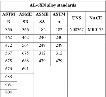
Table 2.1 AL-6XN alloy classifications standards AL-6XN alloy standards
ASTM B ASME SB ASME SA ASTM A UNS NACE 366 366 182 182 N08367 MR0175 462 462 240 240 472 564 249 249 567 675 312 312 675 688 479 479 676 691 688 691 804
However, adding a small amount of nitrogen to the AL-6X alloy eliminates the secondary phase precipitation during fabrication of thick components [11-13]. Therefore, the AL-6XN alloy was developed and used in highly corrosive applications instead of the AL-6X alloy. A company named Allegheny Ludlum Corporation, which specialises in the production of super and advanced alloys, has developed and produced the AL-6XN alloy as an alternative to the AISI 316 alloy (from now on referred as 316 alloy), particularly for resisting seawater [14]. This company had provided (in their own database) the most significant standards that describe the properties and specifications of the AL-6XN alloy.
The AL-6XN alloy specification and classifications are cited in broad standards [15]. The most important standards of the AL-6XN alloy specifications are listed in Table 2.1. However, the AL-6XN alloy has a typical chemical composition consisting of Cr, Ni, Mo, N, P, Si, C and the balance Fe.
Table 2.2 AL-6XN alloy typical chemical composition
Weight (%Vol) Cr Ni Mo N P Si C Fe
10
The weight of these alloying elements varies by a small degree between the standards mentioned in Table 2.1. The typical weights of the alloying elements for the AL-6XN alloy are itemised in Table 2.2.
2.1.2 Material properties and applications
The AL-6XN alloy has some similarities to the ASS alloys, especially the 316 alloy. The microstructure of the AL-6XN alloy is presented by the FCC phase structure, which enables the stainless steel to provide high strength at low temperatures [16]. The AL-6XN alloy is characterised by the addition of the nitrogen alloying element along with high levels of molybdenum and nickel.
The resistance of the chloride stress corrosion cracking (SCC) and the stability of the austenite phase are enhanced by the high level of nickel [17-19]. Excellent resistance to crevice and pitting corrosion is the consequence of adding nitrogen and molybdenum to the alloy microstructure [20, 21]. In contrast, a high percentage of molybdenum in the microstructure of the AL-6XN alloy will promote the construction of the second phases, such as the σ phase. This phase is brittle and harmful to the AL-6XN alloy properties [22, 23].
A low carbon content of 0.03% in the AL-6XN alloy chemical composition prevents the intergranular corrosion when the alloy is used in welding processes. Other grades of stainless steel, such as the 306L, 304L and 300 series, were compared with the AL-6XN alloy. Both the 304L and 306L grades exhibited lower intergranular attack resistance than the AL-6XN alloy. The AL-6XN alloy is also distinguished by the superior mechanical properties combined with higher yield strength. The 300 series stainless steels have lower strength at higher temperatures compared to the AL-6XN alloy [24].
The AL-6XN alloy is commonly used in the following applications [2, 25, 26]:
• Chemical processing systems, e.g. chemical waste and food processing equipment.
• Oil and gas industry, e.g. pipelines, fittings, valves, scrubbers and heat exchangers.
• Offshore and marine structures, e.g. water desalination systems, pumps and transformer cases.
11
The common factor in all these applications is the presence of a corrosive environment. Also, these applications are sensitive to material failure, which means that if the material fails during its working life, it will be difficult to fix or replace the affected components with low effort and cost. Machinability of a material can improve or decrease the working life of the produced components depending on the applied cutting parameters and the machining aspects, Therefore, the machinability of the AL-6XN alloy should be well understood to produce high quality components.
2.2
Machining and machinability of materials
Machinability of a material was defined by Davim and Lalbondre et al. and as the ease of material removal (chips) by the edge of the cutting tool using one of the conventional machining operations (milling, drilling or turning) to produce a satisfactory surface quality at low cost [27, 28]. Machinability of any work material depends on i) the properties of the material; ii) the material and geometry of the cutting tools; iii) the level of process parameters; and iv) the machining environment (dry or wet machining). In addition, the strength, rigidity and stability of the machine also influence the machinability process.
In general, machinability is often judged by: i) the magnitude of cutting forces; ii) tool wear/tool life; iii) surface finish and surface integrity; iv) the cutting temperature; and
v) chip formation and morphology. These factors are considered as indicators of a material machinability. In some industries, the machining process in terms of drilling, milling and turning is a forming process that is conducted to produce smooth surfaces. The predictability of machining steels and stainless steels is poor due to the microstructure phases. The ductile phases lead to common machining issues, such as the formation of the built-up edge on the cutting edge, chipping wear and notch wear. These issues influence the cutting forces value, as well as the quality of the produced surfaces. In contrast, the brittle phase, such as that in cementite, is an abrasive factor during the cutting process that forms different types of wear, such as crater and flank wear, on the cutting tools, which inversely influence the productivity of the machined alloys.
12
2.2.1 Machinability aspects
Cutting forces analysis
When the cutting process is started, the cutting tool contacts the workpiece and, due to this contact, pressure occurs in the contact area between the workpiece and the cutting tool, and then cutting forces and stresses will be created. When the cutting forces are increased, the resultant stresses cause a permanent (plastic) deformation represented by the chip formation and separation of the workpiece.
Estimating the cutting forces for a material machining process is used to eliminate distortions in the machined components and to design the geometry of the cutting tools and tool holders. In addition, cutting force data help in finding the required power to cut the alloy, which in turn assists in choosing the adequate motor drive of the CNC machine [29, 30]. The cutting forces can be precisely predicted using the dynamometer measurements [31-33]. Dynamometers are attached to the machining instrument and used to measure the forces directly from the cutting process. Different forces can be extracted and evaluated from the machining process, as shown in the merchant diagram for the typical cutting forces in Figure 2.1.
From Figure 2.1, Fc is the cutting force responsible for the chip formation and
separation. The direction of the Fc is in the same direction as the feed during the cutting
process. Ft is known as a thrust force, and it is perpendicular to the cutting force and
the feed direction during the cutting process. Fc and Ft can be considered as the
components of the resultant force R. This force R can also be analysed as two separate forces, N and F. The normal force N has a normal direction on the chip–tool contact surface while the friction force F is parallel to the chip-tool contact surface.
The F and N forces are given by equations 2.1 and 2.2.
F = R sin β (2.1) N = R cos β (2.2) Where β is the friction angle, refer Figure 2.1.
13
Figure 2.1 Typical cutting forces components in Merchant circle
Fs and Fn, are the forces acting on the shear plane and can be estimated with respect to
Fc and Ft from equations 2.3 and 2.4:
Fs = Fc cos ϕ - Ft sin ϕ (2.3)
Fn = Fc sin ϕ - Ft cos ϕ (2.4)
Where, ϕ is the shear plane angle, refer Figure 2.1.
Shear plane angle ϕ is calculated by merchant equation 2.5 [34]:
ϕ = π/4 – ½ (β-γ) (2.5) These equations help to evaluate the normal and shear stresses (σn and Ks) in the shear
plane in terms of the shear area. The shear area (As) can be calculated from the cutting
depth value and the shear plane angle (equations 2.6-2.8) [34]:
σn = Fn/As (2.6)
Ks = Fs/As (2.7) Tool
Chip
Workpiece
Shear plane angle ϕ
Rake angle γ F R N Fc Ft Fn Fs t0 tc β β-γ
14
As = w/sin ϕ (2.8)
The amount and direction of the thrust force are influenced by the friction angle (β) and the rake angle (γ) as shown in equation 2.9 [35].
Ft = R sin (β-γ) (2.9)
Estimating the different types of forces during the cutting process increases the machinist awareness of the machined materials and enables the manufacturers to improve their productivity.
Chip formation
The formation of chips during machining significantly affects the machinability of a material and, therefore, it is necessary to understand the mechanism of chip formation. To study the chip formation mechanism, it was assumed, by researchers, that the cutting process was an orthogonal process as shown in Figure 2.2. In an orthogonal cutting process, the cutting edge position is perpendicular to the cutting direction during the cutting process, as shown in Figure 2.2. This assumption is widely used by researchers to avoid issues with the geometry of the cutting tools during machining [36]. When the cutting process is taking place, the cutting edge will cause a shear strain in the machined surface. If the shear exceeds the elastic limits, then a plastic shear will spread along the shear plane. The shear plane, which is a line that splits the machined (deformed) material and the uncut material (Figure 2.3), is inclined by the shear plane angle ϕ from the machined surface (the horizontal plane). The plastic shear will form the plastic deformation of the machined surface and, as a result, metal chips will split from the surface.
Figure 2.3 explains the chips formation criteria. It was assumed by Ernst and Merchant that chips will be a set of plates having the same shape and thickness [37]. The geometries of these plates have been analysed to calculate the plastic shear strain in the machined surface generated by the cutting edge. The shear strain is predicted from the triangle ABC as shown in Figure 2.3-B and C. The shear strain (τ) can be calculated by using the following equations (2.10-2.12) [38].
15
Figure 2.2 Orthogonal metal cutting model [36]
Figure 2.3 Chips formation diagram
τ = AC/BD (2.10) τ = (AD + DC)/BD (2.11) τ is also calculated in turn of ϕ and α from the following equation:
τ = tan (ϕ – γ) + cot ϕ (2.12) Where ϕ is the shear plane angle; γ is the tool rake angle.
X Y A B Workpiece Depth of cut Tool Primary shear zone Secondary shear zone Chip X Y A Strained material Plates of the chip Tool Workpiece Shear plane ϕ γ A B C D ϕ γ ϕ-γ C Plate thickness A B C B
16 Shear plane angle ϕ is given by equation 2.13:
tan ϕ = r cos α / (1 – r sin α) (2.13) Where, r is the chip thickness ratio and is given by equation (2.4):
r = tₒ / tc (2.14)
tₒ and tc, shown in Figure 2.1, are the chip thickness before and after the cutting
process.
Chip thickness ratio r is less than 1, as the tc is higher than the tₒ in the machining
process. The magnitude of tₒ and tc can be estimated by equations 2.15 and 2.16.
tₒ = Ls sin ϕ (2.15)
tc = Ls cos (ϕ – α) (2.16)
Ls is the shear plane length. Types of chips
The chips formed during the cutting process were classified into four categories depending on their shape and colour. The cutting parameters and the properties of the material determine the types of chips and their formation mechanism. Figure 2.4 shows the geometries of the four chip types.
Figure 2.4 Types of chips
A: Continuous chip B: Discontinuous chip
17 These chip types, mentioned in [36, 39-41] are:
1. Chips with a continuous profile are generated if the machined material is classified as a ductile material (Figure 2.4-A). The formed chips have the ability to resist the separation process at their shear planes due to the high elasticity of the ductile machined material. These chips have positive and negative implications during the machining process. On the one hand, a reasonable quality for the machined surface is turned up. On the other hand, the entanglement of chips on the cutting tool can cause accumulation of chips around the tool and the workpiece due to hard chips disposal. A small cutting depth, moderate feed, a high cutting speed, high rake angle and efficient coolant increases the likelihood of continuous chips being produced during machining of ductile materials.
2. Chips of a discontinuous profile are produced when machining materials of brittle microstructures (Figure 2.4-B). When a brittle material undergoes a cutting process, compression stress is created in the formed chip and this causes the chip to separate at its shear plane. As a consequence of repeated separation of chips at the shear plane, an improper surface finish results due to the friction between the formed chip and the cutting tool, which causes wear when the chips slide on the cutting edge.
A high cutting depth, low feed, small rake angle and using inefficient coolant with a low or high cutting speed increases the likelihood of discontinuous chips being formed during the machining of brittle material.
3. The third type of chip is the serrated type of segmented chip (Figure 2.4-C). Serrated chips have a semi continuous profile that consists of two regions, i.e. the concentrated shear region and regions of lower deformation. This type is very common when cutting hard machining materials, such as ASS, superalloys (nickel base) and titanium alloys, with low cutting speed. The strain produced during machining works as a cyclic load and produces the serrated chips. When the cutting speed increases, segments are formed in the chips and separation of the chip segments occurs. However, the heat generated due to the cutting process affects the size of the chip segments. For a low thermal conductivity machined alloy, the heat is concentrated within the chips and localised shear bands are created and result in the formation of narrow segments.
18
4. The final type is a chip with a continuous profile with a built-up edge (BUE) (Figure 2.4-D). The BUE is a small part of the chip that is due to the adhesion of small workpiece fragments to the chip at the shear zone on the tool rake face. A high cutting temperature and high pressure assist the welding of these workpiece fragments to the cutting tool. This adhesion usually appears when low speeds are used to cut a ductile metal. The BUE consists of the machined material pieces and a few pieces of the cutting tool, which causes severe chipping wear when the BUE is separated from the chips. As a result, a low surface finish is obtained due to machining with a worn cutting tool. Applying a large depth of cut, very large feed, low cutting speed, small rake angles and inadequate coolant on the ductile material induce the formation of such chips.
Morphology of chips
The morphology of chips is used to investigate a material behaviour during machining. The behaviour of materials during the cutting process is shown by the chips colour and geometry. As mentioned in the previous section, ASS alloys mostly form segmented type chips during machining. However, these segmented chips can be converted to discontinuous chips due to the formation of a work hardened layer at the primary shear zone and in the chip region.
Although the ductile material creates continuous or segmented chip morphologies during the cutting process, these chip morphologies can change to discontinuous morphologies depending on the degree of work hardening, which also depends on the applied cutting parameters and the cutting environment. Therefore, prediction of the morphology of chips is necessary to estimate the machinability of a material due to its strong relation with tool wear, the quality of the machined surface and work hardening [42, 43].
Changing the cutting parameters during machining affects the magnitude and type of tool wear and hence, this will produce multiple shapes of the formed chips [44, 45]. In contrast, chip formation controls the surface tolerances, and therefore, controls the roughness of the machined components [46]. Researchers have studied the morphology of chips while machining various types of materials.
19
Muñoz Escalona et al. studied the morphology of chips during machining of the 303 ASS alloy [47]. Chips were collected after dry and wet cutting trials. The chips had a yellow (due to high temperature) and white colour when machining the alloy in dry and wet environments, respectively. The chip morphology was serrated and the serration degree increased when the alloy was machined in a wet environment. Mohanty et al. collected continuous and long formed chips after machining stainless steel alloy type 17-4 PH [48]. The chips colour was changed from silver at the beginning of cutting to golden at the end of cutting due to the effect of the accumulated heat. Researchers have also used the chips colour to analyse the cutting tool failure. Morehead et al. studied the chip morphology and its relation to the wear of the cutting tool while machining hardened steel type 52100 and had shown the formation of serrated chips of segments [49]. The distance between two consecutive segments, as well as the serrated end height, was inversely proportion to the progression of the cutting tool flank wear. Also, the applied cutting speed and high cutting tool wear induced segment formation in the chips, which is the opposite behaviour to that seen when increasing the applied feed rate. However, the effect of the depth of cut on the chip segmentation was correlated to the applied cutting speed and feed rate.
Another machining study, conducted by Jin and Liu, investigated the chip morphology of the superalloy type FGH95 [50]. The study displayed that the degree of serration of the chips increased with greater applied cutting speed until the creation of fragmented type chips.
Hua and Shivpuri studied chip morphology by machining the Ti-6Al-4V titanium alloy at low and high cutting speed [51]. Serrated and discontinuous chips were formed at high and low cutting speeds, respectively. These morphologies were found because Ti-6Al-4V is sensitive to internally generated cracks.
Komanduri et al. found a serrated chips morphology when the Ti-6Al-4V was machined regardless of the applied cutting speed [52]. When a high speed camera was used to observe the instantaneous shear, it was found the primary shear zone underwent an unsteady plastic shear during the cutting. Such a shear was the reason behind a catastrophic shear that, in turn, caused the serrated chips.
20
Machinability of the Inconel 718 superalloy exhibited that the morphology of chips influenced the quality of the machined surfaces [53]. Chips with a high thickness were produced when machining the Inconel 718 alloy at a low cutting speed. These chips reduced the wear on the tool rake face but decreased the quality of the machined surfaces (i.e. increased the roughness values).
Thickened chips of low radius were formed during the machining of AISI 304 ASS at low cutting speeds [54]. Researchers concluded that the thicknesses of the chips were controlled by the angle of the shear plane. A low shear plane angle resulted in the formation of chips of high thickness that slowly slide on the cutting tool rake face. Work hardening measurements
Work hardening of a material is the significant increase of the material strength due to plastic deformation triggered by an external load. The external load results from processes such as metal machining, forming, rolling or heat treatment. In machining, the external load is applied when the cutting tool contacts the workpiece and generates strain and stresses. When the strain is in the plastic region, as the chip is formed, the deformed grains crystal structure is affected and produces slip lines and dislocations. The movement and the accumulation of these dislocations with the newly created slip lines in the deformed grains increase the strength of the machined material. Consequently, the hardness values increase and inversely influence the wear of the cutting tool, surface quality and the cutting forces.
The work hardening is measured by measuring the hardness at the deformed layer. The hardness of a material can be defined as the resistance to the permeant surface deformation (plastic deformation caused by the indenters) [55]. The hardness of a material can be measured using various techniques and scales. It can be measured at nano, micro and macro scales depending on the size of the tested surface area, material properties and the applied load.
The microhardness measurement is an essential test used by researchers to measure the hardness and work hardening of the machined surfaces. The microhardness measurements can be conducted using techniques such as Vickers hardness (HV), Rockwell hardness (HR), Brinell hardness (HB) and Knoop hardness (HK) [56].
21
The Vickers hardness test is the main test used in this thesis to measure the work hardening, as demonstrated later in other chapters. Therefore, this section focuses on explaining the importance of this test and the main equations used to calculate the microhardness of the surface. In the Vickers hardness test, a diamond shape indenter is used to produce the plastic deformation on the tested surfaces. The microhardness value can then be measured from the area of the indentation and the applied force that caused the permanent deformation, as shown in Figure 2.5.
Figure 2.5 Vickers indentation geometry [57]
From Figure 2.5, shows the average value of the two diagonals d1 and d2. The angle 136° is the angle between the opposite faces of the pyramid indenter. The microhardness of a material HV then can be calculated from the following equation 2.17 [56]:
HV= 𝐹
𝐴 (2.17)
Where F: is the applied load in N, and A: is the area of the indentation in mm. A is given by equations 2.18 and 2.19:
A= 𝐷 2 2∗sin136 2 (2.18) A= 𝐷 2 1.854 (2.19) HV= 0.102∗1.854 𝐹 𝐷2 , HV= 0.1819 𝐹 𝐷2 (2.20) d1 d2