ECOLE DE TECHNOLOGIE SUPÉRIEURE UNIVERSITÉ DU QUÉBEC
MANUSCRIPT-BASED THESIS PRESENTED TO ÉCOLE DE TECHNOLOGIE SUPÉRIEURE
IN PARTIAL FULFILLMENT OF THE REQUIREMENTS FOR THE DEGREE OF DOCTOR OF PHILOSOPHY
PH.D.
BY
Sheida SARAFAN
ELECTRON BEAM WELDING PROCESS FOR JOINING THICK GAGE SECTION OF MARTENSITIC STAINLESS STEELS
MONTREAL, JANUARY 28, 2016
This Creative Commons licence allows readers to download this work and share it with others as long as the author is credited. The content of this work may not be modified in any way or used commercially.
BOARD OF EXAMINERS THIS THESIS HAS BEEN EVALUATED BY THE FOLLOWING BOARD OF EXAMINERS
Prof. Henri Champliaud, Thesis Supervisor
Département de Génie Mécanique, École de technologie supérieure Dr. Priti Wanjara, Thesis Co-supervisor
National Research Council, Institute for Aerospace Research Prof. Pascal Bigras, Chair, Board of Examiners
Département de Génie de la production automatisée, École de technologie supérieure Dr. Denis Thibault, Member of the jury
Institut de recherche d'Hydro-Québec (IREQ) Emeritus Prof. Doug J. Boyd, External Evaluator
Department of Mechanical and Materials Engineering, Queen’s University Dr. Javad Gholipour Baradari, Member of the jury
National Research Council, Institute for Aerospace Research
THIS THESIS WAS PRENSENTED AND DEFENDED
IN THE PRESENCE OF A BOARD OF EXAMINERS AND THE PUBLIC ON JANUARY 14, 2016
This dissertation is lovingly dedicated to my mother, my family and
my husband for their support and encouragement. Their constant love have sustained me throughout my life.
ACKNOWLEDGMENTS
I would first like to express my sincere gratitude and appreciation for my supervisor Professor Henri Champliaud and my co-supervisor Dr. Priti Wanjara whose guidance were indispensable for my doctoral research. I am grateful to them for their constant encouragement, guidance and support for my research as well as my professional development.
I would like to acknowledge Professor Doug J. Boyd, Dr. Denis Thibault, Dr. Javad Gholipour Baradari, and Professor Pascal Bigras for serving on my thesis committee. I greatly appreciate their taking the time to critically review this doctoral dissertation.
I would like to thank Jean-Benoît Lévesque, Etienne Dallaire, Dr. Jacques Lanteigne at IREQ, as well as Louis Mathieu and Michel Sabourin at ALSTOM for providing the experimental data, materials and consultants. I would also like to thank Xavier Pelletier, Eric Poirier, Maxime Guerin and Marius Banu at the National Research Council of Canada (NRC) for their technical assistance related to electron beam welding, metallographic preparation, tensile testing with digital image correlation and distortion measurement and their valuable suggestions during my thesis research. I am very grateful to all my colleagues for their support during my research and for making my stay at NRC and ETS a memorable one.
Sincere appreciation is extended to the many people who have helped bring this to a fruitful end. Gratitude is expressed to my parents, Mehdi and Nafiseh, who provided me with the educational opportunity. I thank my husband, Behzad, who has always supported me and helped me during this dissertation.
Finally, I would like to acknowledge the financial contribution of the Consortium de recherche en fabrication et réparation des roues d’eau (CReFaRRE) and the Natural Sciences and Engineering Research Council of Canada (NSERC) for supporting this research work.
SOUDAGE PAR FAISCEAU D’ELECTRONS SOUS VIDE DE FORTES EPAISSEURS EN ACIER INOXYDABLE MARTENSITIQUE
Sheida SARAFAN RÉSUMÉ
La fabrication durable pour l'assemblage des turbines utilisées dans les systèmes de production d'hydroélectricité est le moteur du développement de technologies avancées pour réduire les coûts de fabrication tout en assurant une haute performance sur la durée de vie du produit. La roue de turbine, un élément essentiel dans les systèmes hydrauliques de production d'énergie, est composée de trois éléments majeurs, la couronne, les aubes et la ceinture, assemblés par soudage. Le soudage par faisceau d'électrons (EBW) sous vide à haute densité d'énergie peut jouer un rôle très important dans la conception et la fabrication d'une roue de turbine qui est fabriquée à partir de composants à très fortes épaisseurs. En effet, ce procédé a la capacité d’atteindre une pénétration profonde avec un faible apport de chaleur, donnant ainsi une soudure avec d’étroites zones affectées thermiquement (ZAT) et une faible distorsion.
Dans cette thèse, la soudabilité par faisceau d’électron (EBW) de fortes épaisseurs d’acier inoxydable martensitique (13% Cr-4% Ni) à faible taux de carbone, largement utilisé dans la fabrication de turbines hydrauliques, a été étudiée. En particulier, le soudage en une seule passe (BOP) et d’un joint bout à bout sans préparation à démontrer qu’il est possible de souder sur une profondeur de 60 mm à 90 mm des plaques en CA6NM et UNS S41500. Les soudures ont été réalisées avec une soudeuse à faisceau d'électrons de 42 kW sous vide sans utiliser de métal d'apport. Les caractéristiques des échantillons soudés ont été mesurées: évaluation de la microstructure dans la zone de fusion (FZ) et dans les ZAT, distribution de la dureté, ainsi que les effets du préchauffage et du traitement thermique après soudage. Les contraintes résiduelles longitudinales dans la section droite d’un joint soudé ont été mesurées par la méthode du contour.
Le comportement mécanique des soudures, localement et globalement, a été déterminé par un essai de traction à température ambiante en utilisant un système automatisé de corrélation d’images numériques (DIC). Les mesures de déformations montrent que les propriétés en tension, dans la condition tel que soudé et dans la condition traité thermiquement après soudage, rencontrent les critères d’acceptabilité pour des applications hydroélectriques selon les normes ASME sections VIII & IX. Le système ARGUS combiné au système DIC a également été utilisé pour mesurer la distorsion des assemblages soudés par EBW. Finalement, la distribution longitudinale des contraintes résiduelles a été évaluée par la méthode du contour dans une section droite perpendiculaire au sens de la soudure, pour les aciers CA6NM et UNS S41500, dans les conditions tel que soudé et traité thermiquement après soudage.
Mots clés: soudage par faisceau d’électrons, section épaisse, acier inoxydable martensitique, microdureté, microstructure, système numérique de corrélation d'images, propriétés en traction, contraintes résiduelles, méthode du contour
ELECTRON BEAM WELDING PROCESS FOR JOINING THICK GAGE SECTION OF MARTENSITIC STAINLESS STEELS
Sheida SARAFAN
ABSTRACT Sustainable manufacturing for assembly of turbines used in hydro power generation systems is driving the development of advanced technologies targeted to reduce life-cycle costs whilst assuring high performance over the prolonged product life-span. The turbine runner, a critical component in hydro power generation systems, requires weld assembly between the crown, band and blade sub-components. With due consideration of the thick-gauge sections involved, design and fabrication of a turbine runner that integrates a high energy density technology for assembly, such as vacuum electron beam welding (EBW), has marked potential to achieve deep penetration with a low heat input, thereby rendering a weldment with narrow heat-affected zones (HAZ) and low distortion.
In this study, the weldability of thick-gauge section of cast and wrought grades of 13%Cr-4%Ni low carbon martensitic stainless steels that are widely utilized in hydro turbine manufacturing was investigated by EBW. Particularly, a single pass bead-on-plate (BOP) and/or butt joint in 60 mm to 90 mm thick CA6NM and UNS S41500 plates were carried out using a 42 kW high vacuum EBW system without using filler addition. Preheating before welding and post-weld heat treatment of the welds was also studied. The characteristics of the weldments, including the size of the fusion zone (FZ) and HAZ, their phase constituents, microstructures and hardness evolution, were evaluated.
The mechanical response of the welds, locally and globally determined through uniaxial tensile testing at room temperature with an automated non-contact three-dimensional (3D) digital image correlation (DIC) deformation measurement system, indicated that the tensile properties in both the as-welded and PWHTed conditions met the acceptance criteria in the ASME Section VIII & IX standard. A non-contact photometry system was also used to measure the distortion after EBW. In addition the distribution in the longitudinal residual stresses was mapped by the contour method for both CA6NM and UNS S41500 in the as-welded and PWHTed conditions.
Keywords: electron beam welding, thick gauge section, martensitic stainless steel, microhardness, microstructure, digital image correlation system, tensile properties, residual stresses, contour method
TABLE OF CONTENTS
Page
INTRODUCTION ...1
CHAPITRE 1 CHALLENGES AND OBJECTIVES ...5
CHAPITRE 2 LITERATURE REVIEW ...7
2.1 Electron beam welding (EBW) ...7
2.1.1 Principles of EBW ... 7
2.1.2 Deep penetration welding by EBW ... 9
2.1.3 Electron beam welding parameters ... 11
2.1.4 Electron beam welding of thick section metals ... 14
2.2 Low carbon martensitic stainless steels ...15
2.2.1 Alloying elements in martensitic stainless steels ... 16
2.2.2 Phase transformation in martensitic stainless steels ... 18
2.2.3 Different zones in martensitic stainless steels weldment ... 19
2.2.4 Tensile properties in martensitic stainless steels ... 22
2.3 Principles of DIC ...24
2.3.1 Application of 3D DIC for local tensile properties in welded samples .... 26
2.4 Weld distortion and residual stresses ...28
2.4.1 Measurements of residual stress by contour method ... 28
2.4.2 Effect of phase transformation on distortion and residual stresses in welding ... 30
2.5 Conclusions ...33
CHAPITRE 3 CHARACTERISTICS OF AN AUTOGENOUS SINGLE PASS ELECTRON BEAM WELD IN THICK GAGE CA6NM STEEL ...35
3.1 Abstract ...35
3.2 Introduction ...36
3.3 Experimental procedure ...37
3.3.1 Material ... 37
3.3.2 Preparation for welding... 38
3.3.3 Welding Procedure ... 39
3.3.4 Metallographic and microhardness testing techniques ... 41
3.4 Results and discussions ...43
3.4.1 Temperature evolution ... 43
3.4.2 Microstructural and hardness evolution of as-welded CA6NM ... 45
3.4.3 Microstructural and hardness evolution of PWHTed CA6NM ... 52
3.5 Conclusions ...58
3.6 Acknowledgments...59
CHAPITRE 4 GLOBAL AND LOCAL CHARACTERISTICS OF AN AUTOGENOUS SINGLE PASS ELECTRON BEAM WELD
IN THICK GAGE UNS S41500 STEEL ...63
4.1 Abstract ...63
4.2 Introduction ...65
4.3 Experimental Procedure ...67
4.3.1 Materials ... 67
4.3.2 Preparations for welding ... 68
4.3.3 Welding procedure ... 69
4.3.4 Metallographic and microhardness testing techniques ... 70
4.3.5 Tensile testing methodology with DIC ... 72
4.4 Results and Discussions ...75
4.4.1 Microhardness and microstructural evolution in the as-welded and PWHTed conditions ... 75
4.4.2 Tensile properties ... 83
4.4.3 Local tensile properties ... 91
4.5 Conclusions ...94
4.6 Acknowledgments...96
4.7 References ...96
CHAPITRE 5 EVALUATION OF DISTORTION AND RESIDUAL STRESSES IN ELECTRON BEAM WELDED HYDROELECTRIC TURBINE MATERIALS ...101
5.1 Abstract ...101
5.2 Introduction ...102
5.3 Experimental procedure ...103
5.3.1 Materials ... 103
5.3.2 Preparations for welding ... 104
5.3.3 Distortion measurement after welding ... 106
5.3.4 Residual stress measurement by contour method ... 107
5.4 Results and discussion ...108
5.4.1 Distortion evolution in EB butt welds ... 108
5.4.2 Longitudinal residual stress evolution in EB butt welds in the as-welded and PWHTed conditions ... 109
5.5 Conclusions ...112
5.6 Acknowledgments...113
5.7 References ...113
CONCLUSIONS ...117
RECOMMENDATIONS AND FUTURE WORK ...121
LIST OF TABLES
Page Table 2-1 The chemical compositions (wt.%), calculated transformation
temperature range (∆T (ºC)) and measured distortion θ for two
manual metal arc, multi-pass weld deposits (Bhadeshia, 2004) ... 32 Table 3-1 EDX microanalysis (wt. %) of phases in EB welded CA6NM... 51 Table 3-2 Comparison of HAZ2 characteristics in EB welded CA6NM
with reported findings for martensitic stainless steels ... 52 Table 3-3 XRD and image analysis results in as-weld and PWHT
conditions CA6NM ... 56 Table 4-1 Tensile sample dimensions extracted from the transverse cross
section of the EB weld ... 73 Table 4-2 Fraction of delta ferrite and retained austenite measured by
XRD and image analysis ... 80 Table 4-3 Carbon content and average hardness in the six distinct regions
of welded martensitic stainless steels ... 83 Table 4-4 Global tensile properties and failure location for UNS S41500 ... 84 Table 4-5 Local tensile properties in FZ and HAZ extracted from Type A,
B, and C samples ... 94 Table 5-1 As-received materials conditions and chemical compositions
used in this study ... 104 Table 5-2 Experimental design for the EB welds ... 106
LIST OF FIGURES
Page Figure 1-1 (a) Francis turbine runner (Boudreault et al., 2014) and components
(b) crown, (c) band, and (d) blades, respectively from left to right (Saeed, Galybin et Popov, 2010) ... 2 Figure 2-1 Schematic of butt joint geometry in different arc welding processes
(Pilarczyk et Węglowski, 2014) ... 8 Figure 2-2 Schematic of EBW and its gun (Handbook, 1993) ... 9 Figure 2-3 Different steps of EB deep penetration (Schultz, 1993) ... 10 Figure 2-4 (a) Definition of beam active parameter (Arata, 1973), (b) effect of
beam focusing on the penetration (Kohyama et al., 1984) ... 13 Figure 2-5 The macro section of the EB weldment (scale in cm) (Srinivasan,
Sharkawy et Dietzel, 2004) ... 15 Figure 2-6 Phase diagram: (a) Fe-Cr, (b) Fe-Cr-Ni, and (c) Fe-Cr-with
different Ni (Folkhard et Rabensteiner, 1988) ... 17 Figure 2-7 Ternary Fe-Cr-C phase diagram at 13%Cr (Folkhard et
Rabensteiner, 1988),... 17 Figure 2-8 TTT diagram of 410 stainless steels (Atkins, 1980) ... 18 Figure 2-9 Optical micrographs revealing tempered martensite in FZ: (a) with
dendritic structure and (b) higher magnification of (a) (Srinivasan et al., 2004) ... 19 Figure 2-10 Optical micrographs of the EB SMSS weldment: (a) FZ and 3
HAZs, (b) FGHAZ and HAZ, (c) CGHAZ and FGHAZ at higher magnification, (d) HAZ zone adjacent to BM at higher
magnification (Srinivasan et al., 2004) ... 20 Figure 2-11 Microhardness profile of the SMSS EB weld cross section after
PWHT (Srinivasan et al., 2004) ... 22 Figure 2-12 Fracture surface appearance of EB welded SMSS tested in air: (a)
an overview of the fracture (showing the cup and cone fracture) and (b) fracture surface showing dimples (Srinivasan et al., 2004) .... 23 Figure 2-13 Speckle pattern on the measured surface ... 24
Figure 2-14 Typical schematic of the 3D DIC technique. ... 25 Figure 2-15 Schematic illustration of matching procedures of the 3D DIC
(Tang et al., 2012) ... 25 Figure 2-16 True strain-stress curves calculated by extensometer and DIC with
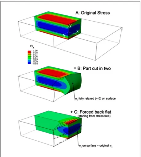
different gage lengths (PI et al., 2010). ... 27 Figure 2-17 Contour method principle for mapping residual stresses on one
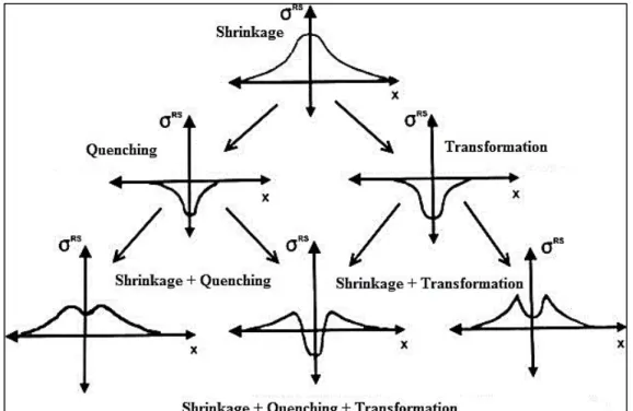
quarter of the original body (Prime et DeWald, 2013) ... 29 Figure 2-18 One solution to remove errors due to the EDM cut ... 30 Figure 2-19 Change of residual stress due to metallurgical processes during
welding (Macherauch et Hauk, 1987) ... 31 Figure 2-20 Schematic diagrams representing the formation mechanism of
residual stresses in relation to Ms and Mf temperatures
(Shiga et al., 2010) ... 32 Figure 3-1 (a) The normalizing and tempering thermal cycles applied to the
cast CA6NM material (b) the as-received cast microstructure of the normalized and tempered CA6NM (OMI) ... 39 Figure 3-2 Schematic of the CA6NM coupon (with dimensions) used for BOP
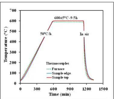
welding. The run on and run off tabs as well as the location of the different thermocouples are indicated. ... 39 Figure 3-3 Preheat treatment of the coupon ... 40 Figure 3-4 Post-weld heat treatment cycle applied to the EB weld ... 41 Figure 3-5 (a) Typical thermal cycle showing the temperature evolution
during preheating by EBZHT and subsequent EB welding and cooling of the CA6NM (b) horizontal and (c) vertical cracks occurring in the FZ of CA6NM welds in the absence of
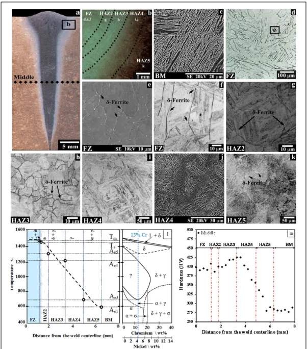
preheating, and (d) crack free... 45 Figure 3-6 As-welded CA6NM: (a) macrostructure of the transverse weld
cross-section (OMI) (b) HAZ sub-regions adjacent to the FZ with the absence of HAZ1 (OMI), (c) SEI of BM microstructure (OMI given in Figure 3-1b), (d-f) FZ microstructure selectively etched for delta ferrite (OMI and SEI), (g) HAZ2 microstructure (OMI), (h) HAZ3 microstructure (OMI), (i-j) HAZ4 microstructure (OMI and SEI), (k) HAZ5 microstructure (OMI), (l) schematic diagram showing the microstructural changes in the low and high
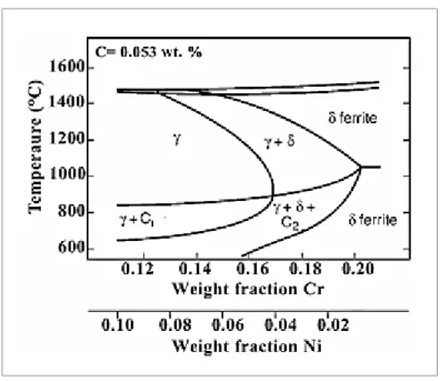
diagram (Folkhard et Rabensteiner, 1988), and (m) microhardness profile at the mid-thickness ... 49 Figure 3-7 Calculated quasi-binary equilibrium phase diagram for
Fe-Cr-Ni-0.053C (Lippold et Kotecki, 2005) (C1 and C2 are M23C6 and M7C3 carbides) ... 50 Figure 3-8 2D Microhardness map of fully penetrated CA6NM welds in the (a)
as-welded and (b) PWHTed conditions ... 54 Figure 3-9 PWHTed CA6NM: (a) microhardness profile at mid-thickness and
(b) macrostructure of transverse cross-section ... 55 Figure 3-10 XRD pattern for the PWHTed microstructure in the (a) BM and (b)
FZ ... 55 Figure 3-11 Microstructure in PWHT condition: (a) FZ, (b) HAZ2, (c) HAZ3,
(d) HAZ4, (e) HAZ5 and (f) BM ... 58 Figure 4-1 The normalizing and tempering thermal cycles applied to UNS
S41500 prior to EBW ... 68 Figure 4-2 Schematic of the UNS S41500 coupon (with dimensions) used
for bead-on-plate welding. The run on and run off tab
lengths are indicated ... 69 Figure 4-3 PWHT cycle applied after EBW ... 70 Figure 4-4 Tensile samples extracted from the transverse cross section of
the EB welds: (a) sub-size (As-welded and PWHTed), (b) Type A and Type C, and (c) Type B samples ... 73 Figure 4-5 (a) MTS tensile testing configuration showing the position of the
laser extensometer relative to the two CCD cameras of the Aramis® system, (b) etched side of the tensile sample showing the reflective tape applied to demarcate the gage length and (c) opposite side of the tensile sample that was painted with a speckle pattern ... 75 Figure 4-6 OM images of the macrostructure showing the entire transverse
cross section of EB welded UNS S41500 in: (a) as-welded and (b) PWHTed conditions ... 76 Figure 4-7 Two- and three-dimensional hardness maps for the entire transverse
section of the EB welds: (a) and (c) as-welded, and (b) and (d)
Figure 4-8 (a) Hardness profile across the as-welded and PWHTed EB welds at a position of 22 mm under the top surface, and (b) average hardness in the six different regions of the as-welded and PWHTed EB welds (with the error bars representing two
standard deviations of uncertainty) ... 78 Figure 4-9 OM images of the microstructure in as-welded UNS S41500:
(a) BM, (b) HAZ5, (c) HAZ4, (d) HAZ3, (e) HAZ2, and (f) FZ (with the absence of HAZ1) ... 79 Figure 4-10 Effect of EBW, PWHT and tensile sample geometry on the global
tensile properties of UNS S41500: (a) YS, (b) UTS, and (c) %El. Two standard deviations of uncertainty are also indicated by
the error bars. ... 85 Figure 4-11 Typical failure locations in standard sub-size geometry samples
that were tensile tested: (a) BM, (b) As-welded UNS S41500 and (c) PWHTed samples ... 85 Figure 4-12 Typical fracture locations and associated 2D hardness maps in: (a)
Type A, (b) Type B, and (c) Type C tensile samples extracted from as-welded UNS S41500 ... 87 Figure 4-13 Images observed using a confocal LSM that reveal (a) the cup and
(b) the cone ductile fractures surfaces of the as-welded
UNS S41500 that failed in the BM ... 88 Figure 4-14 SEI of the tensile fracture surfaces for the: (a) BM, (b) As-welded,
(c) PWHTed, (d) Type A, (e) Type B, and (f) Type C samples ... 89 Figure 4-15 Typical images of the tensile fracture surfaces for: (a) BM,
As-welded and PWHTed samples that failed in the BM and
(b) Type A, B and C samples that failed in the FZ ... 90 Figure 4-16 Major strain distribution map within the sample gage length as
calculated by the Aramis® system just before failure for: (a) As-welded, (b) PWHTed, (c) Type A, (d) Type B,
(e) Type C samples... 91 Figure 4-17 Distribution of the major strain along the median axis of the tensile
sample gage length just prior to rupture: (a) BM, (b) As-welded, (c) PWHTed, (d) Type A, (e) Type B, and (f) Type C. The arrow
Figure 4-18 Local mechanical response of the FZ, high temperature HAZ (HAZ2 and HAZ3) and HAZ4 relative to the global stress–strain behavior measured using: (a) Type B and (b) Type C samples ... 94 Figure 5-1 S chematics showing details related to assembly before welding
and sectioning for residual stress measurement (a) the two coupons tack welded on each end, (b) the clamping fixture mounted to the worktable of the EBW system, and (c) Sectioning of the welded assembly by EDM along a transverse plane at
the mid-length position ... 105 Figure 5-2 Argus set up showing the high contrast black dot pattern (grid)
on the EB welded assembly with the scale bars and encoded
measurement targets (a) top surface, and (b) bottom surface ... 107 Figure 5-3 Out-of-plane displacements of the EB welds in the as-welded
condition (a) map of UNS S41500, (b) map of CA6NM, and (c) profiles at the mid-length position ... 109 Figure 5-4 Longitudinal residual stress distributions in the EB welds (a)
As-welded UNS S41500, (b) As-welded CA6NM, (c) PWHTed UNS S41500, and (d) PWHTed CA6NM ... 111
LIST OF ABREVIATIONS AV Accelerating voltage BC Beam current BF Beam focus BM Base metal BOP Bead-on-plate CCD Charge-coupled device
DBTT Ductile-to-brittle transition temperature
DIC Digital image correlation
EB Electron beam
%El. Total percent elongation
EBW Electron beam welding
EBZHT Electron beam zonal heat treatment
EDM Electro-discharge machining
EDS Energy dispersive spectroscopy
FCAW Flux-cored arc welding
FE Finite element
fps Frames per second
FZ Fusion zone
G Gage length
GMAW Gas metal arc welding
GTAW Gas tungsten arc welding
h Hours
HAZ Heat affected zone
HLAW Hybrid-laser arc welding
LSM Laser scanning microscope
OM Optical microscope
PMZ Partial melted zone
PWHT Post-weld heat treatment
S Welding speed
SEI Secondary electron imaging
SEM Scanning electron microscopy
SMSS Supermartensitic stainless steel
T Temperature
TTT Time-temperature-transformations
UTS Ultimate tensile strength
XRD X-ray diffraction
YS Yield strength
ZHT Zonal heat treatment
2D Two-dimensional
LIST OF SYMBOLS AND UNITS OF MEASUREMENTS Symbol Unit Description
ab - Beam active parameter
Ac1 °C Start temperature of austenite formation on heating
Ac3 °C Finish temperature of austenite formation on heating
Ac4 °C Start temperature of delta ferrite formation on heating
Ac5 °C Finish temperature of delta ferrite formation on heating
D m Beam diameter Do m Object distance DF m Focal length HV Vickers Hardness K mm2/s Thermal diffusivity k W/(mK) Thermal conductivity
MS °C Martensite start temperature
Mf °C Martensite finish temperature
Tm °C Melting point t m Thickness TTT - Time-temperature-transformations α - Alpha-ferrite δ - Delta-ferrite γ - Austenite
INTRODUCTION
Hydropower is a source of renewable energy that currently represents the 16% global electricity generation by the end of 2008 (Kumar, 2011). Although hydropower is an established technology for electricity generation, research and development is required for improving industrial knowledge, environmental performance and reducing the operational costs. To answer to the necessity of research and development in electricity generation, the CREFARRE (Consortium de recherche en fabrication et réparation des roues d’eau) program was conceived in January 2011. Two universities (École de technologie supérieure and École Polytechnique de Montréal), two research centers (IREQ – Institut de recherche d'Hydro-Québec and NRC-CNRC–National Research Council of Canada) as well as two industrial leaders (Hydro-Québec and Alstom) were involved in this project. This dissertation is a part of the larger program on manufacturing and repair of turbine runners (Hydro-Québec, 2011). The priority in this research and development is improving technologies for the design, manufacturing and demonstration of next generation cost-effective turbines runners, the core element of the hydropower system, which is engineered to operate for decades in a hydro-abrasive environment (erosion, corrosion, cavitation).
Considering the geometric dimensions of Francis turbines runner in hydropower system, the main challenges in turbine manufacturing are shaping and assembly of components. As each Francis turbine is made of different parts with different geometries and curvatures, a reliable joining process for their assembly is required. The different components of the present day turbines including blades, band and crown, as shown in Figure 1-1a-d, are assembled together by T-joint geometry with a conventional joining processes such as gas tungsten arc welding (GTAW) or techniques with solid wires or flux-cored wires. The inherent and intensified stresses of the joint areas of the circular-shaped transition between the blades and the band or crown of the Francis turbine runner, cause high stresses concentrations and are thus the most critical locations for initiating cracks at any weld defect that may be present. Therefore, development and replacement of conventional welding processes with advanced welding processes to manufacture sound joints is vital for having a reliable runner.
Figure 1-1 (a) Francis turbine runner (Boudreault et al., 2014) and components (b) crown, (c) band, and (d) blades, respectively from left to right (Saeed, Galybin et Popov, 2010)
Up to now, the application of a high energy density joining technology, electron beam welding (EBW), was not considered for the assembly of Francis turbine runners due to the site welding requirements and size-related complexities of the parts to be assembled or repaired. However, with the recent advancements in high energy density joining technologies in combination with advanced computer aided design, the manufacturing requirements for the assembly of hydropower turbine elements may be addressable through weldability research and development. Moreover, utilizing EBW without filler addition and joint gap preparation can result in less inhomogeneity in the mechanical and microstructural properties in the electron beam (EB) weld due to the single pass process, whilst saving raw materials, production time, energy and costs.
Deliberating on the hydro-abrasive conditions (head or vertical drop, flow rate, sand/silt content) of hydropower turbines, materials used for this application must have long-term fatigue life performance as well as good wear and corrosion resistance. Thus, cast or wrought forms of martensitic stainless steels containing 13%Cr-4%Ni are the typical materials selected for the manufacture of Francis turbine runners due to a combination of characteristics (e.g. relatively high strength, corrosion resistance, good weldability) that overall render a superior performance of the assembly over a prolonged life.
In this manuscript-based thesis, a pioneer research for the feasibility of autogenous EBW (no filler addition) for joining thick gage section (up to 90 mm) of two martensitic stainless steels, CA6NM (cast) and UNS S41500 (wrought), containing 13%Cr-4%Ni, with only a single pass without filler metal addition has been studied. The evaluation of the
microstructure, microhardness, tensile properties and residual stresses of the EB welded martensitic stainless steels at the fusion zone (FZ) and heat affected zones (HAZs) were addressed in both as-welded and post-weld heat treated (PWHTed) conditions. In addition, a procedure for electron beam zonal heat treatment (EBZHT) was successfully developed and demonstrated for the first time with a defocused beam for preheating martensitic stainless steels inside the vacuum chamber. Another state-of-the-art procedure was using digital image correlation (DIC) system to characterize the local tensile properties in the FZ and HAZs and distortion measurement in the thick gage sections of martensitic stainless steels welded by EBW. In addition, for the first time, the longitudinal residual stresses in 90 mm thick EB welded martensitic stainless steels were measured by the contour method.
Specifically, in Chapter 1, a description of the challenges and objectives are given to provide a context to the present research work. Then in Chapter 2, a literature survey was conducted to review the state-of-the-art knowledge on martensitic and supermartensitic stainless steels, their joining processes and procedures, DIC systems for characterizing the mechanical properties and distortion, and the contour method for determining the residual stresses with an emphasis on EBW of thick gage sections. In Chapter 3, published in the International Journal of Advanced Manufacturing Technology, 2015, vol. 78, no 9-12, p. 1523-1535, the feasibility of EBW 60 mm thick CA6NM with a single pass without filler metal addition and using an EBZHT for preheating was validated. In addition, a detailed characterization of the microstructure and microhardness in different distinct regions of the EB weld in both the as-welded and PWHTed conditions were reported. In Chapter 4, submitted to the journal of Materials Science and Engineering A, in August 2015, the feasibility of EBW 88 mm thick UNS S41500 martensitic stainless steel welded without preheating was ascertained. The global and local mechanical properties, including microhardness and tensile properties (by using DIC) in the different regions of the weldment, were explained. In Chapter 5 accepted for publication in the journal of Science and Technology of Welding and Joining, in December 2015, the distortion and longitudinal residual stresses in 90 mm thick gage sections of UNS S41500 and CA6NM materials assembled by EBW were evaluated in the as-welded and/or PWHTed conditions. Finally, the
conclusions, recommendations for future work and a section on the statement of originality and contributions to knowledge are provided.
CHAPITRE 1
CHALLENGES AND OBJECTIVES
The main challenges in hydroelectric turbine manufacturing considering the size and geometry of components are the forming and welding processes required for production. Specifically, each hydroelectric turbine has a runner that is the heart of the turbine and is made of many parts with various geometries and shapes. Therefore a reliable joining process for their assembly is required, especially considering that the joint area comprises high stresses and is the most critical location for initiating cracks. Presently, the different turbine runner components continue to be assembled and repaired by conventional joining processes. Considering the size and thickness of the components, assembly via conventional arc welding processes such as flux-cored arc welding (FCAW) process requires multiple passes to fill the joint gap. The application of a multi-pass process imparts a high heat input that leads to high residual stresses and distortions, microstructural inhomogeneity and performance variability across the weldment. By contrast, EBW, as a high-energy density welding process, can join a thick gage section using a single pass without filler addition or groove-machining. In spite of being an advanced process, EBW has several challenges for joining thick gauge sections of martensitic stainless steel grades employed for hydroelectric turbine manufacture, such as (1) large temperature gradients, (2) high cooling rates, (3) pre-existing defects and cracking susceptibility of the base material, (4) pre-weld preparation and clamping and (5) gap tolerance between the abutting interfaces.
The purpose of this project was thus to develop an automated/advanced assembly method, as an alternative to conventional arc welding for hydraulic runner manufacturing, by (1) improving and extending the existing knowledge on EBW of thick gage sections, (2) investigating the weldability of two important hydroelectric turbine materials CA6NM and UNS S41500 that are low carbon martensitic stainless steels grades, (3) studying the process parameters, weld integrity and penetration depth, (4) understanding the different phase constituents of the microstructures in the different regions of the EB weldments, (5) relating the evolution in the mechanical properties across the weldment to the local microstructural
features and (6) quantifying the distortion and resulting residual stress. Through this feasibility study, the next generation of engineers can become familiar with the potential of a single pass electron beam welding process for assembly of hydroelectric turbine materials and understand the related design for manufacturing criteria for industrial application.
Thus, in this project, process development with EBW was studied for joining thick sections of UNS S41500 (wrought grade) and CA6NM (cast grade), two martensitic stainless steels that have a similar nominal composition of 13%Cr and 4%Ni. The weldabilities of UNS S41500 and CA6NM were studied by varying the process parameters such as the power, beam focal position, welding speed, gap size, preheating temperature, and PWHT. The resulting weld bead geometry, weld integrity (voids, cracking, penetration depth), phase constituents in the FZ and HAZs, and microhardness were characterized using different techniques, including optical microscope (OM), laser scanning microscope (LSM), scanning electron microscope (SEM), x-ray diffraction (XRD) and microindentation hardness testing. The global and local tensile mechanical properties of the welds were measured through uniaxial tensile testing using DIC. In addition, an automated optical measuring system was used to determine the angular distortion of the welded assemblies. The longitudinal residual stress distribution was also determined by the contour method. In general, the design of experiments for welding (including preheating and PWHT) as well as characterization of the weldments was performed according to recommended guidelines stipulated in various standards such as ASTM-E8, ASME Section VIII & IX.
CHAPITRE 2
LITERATURE REVIEW
This Chapter provides a brief description of the EBW process including principles, mechanism and parameters of EBW. The next section describes martensitic stainless steels namely 13%Cr- 4%Ni, which are widely used in the hydropower turbine runners and using DIC method to measure the tensile properties. Then, work related to welding-induced distortion is considered. Finally, research related to analysis of the residual stresses during welding measured by the contour method is described.
2.1 Electron beam welding (EBW) 2.1.1 Principles of EBW
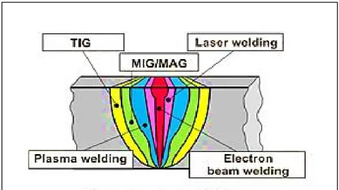
EBW is a mature manufacturing technology that has a demonstrated capability of joining thick gauge section materials in a single pass with considerably lower heat input than conventional arc welding processes. The weldment is typified by a high depth to width ratio, narrow FZ and HAZ, low residual stresses and distortion, and high mechanical performance (Meleka, 1971). The schematic of different geometries of a butt joint in different arc welding processes is compared with EBW in Figure 2-1. The EBW is a fusion welding process for joining a broad range of similar and dissimilar materials (Sun et Karppi, 1996) by bombardment of the material surface with high energy electrons. Electrons emitted from a filament or a cathode (usually tungsten) with a low current (e.g. 50–1000 mA), which is attached to a high voltage supply (30–150 kV), are accelerated and focused on the work piece (Meleka, 1971; Pitrou, 1975).
Figure 2-1 Schematic of butt joint geometry in different arc welding processes (Pilarczyk et Węglowski, 2014)
The combination of a filament or an anode, and a bias cup is called the EB gun that is a main part of the EBW system as shown schematically in Figure 2-2 (Handbook, 2004; Mladenov et al., 1998). Due to scattering of the electrons at atmospheric environment, the EBW is usually carried out in a vacuum chamber under pressure of 10-5 torr for deep penetration in thick gage sections, however it is possible to use the EBW in medium vacuum (Dugdale, 1975) or non-vacuum systems (Radtke, 1964) when less penetration depth is desired. The application of EBW in a vacuum environment prevents contamination of the molten weld pool from atmospheric elements, as well minimizes diffusion/divergence of the focused EB from scattering and ionisation under atmospheric pressure. In comparison, non-vacuum EBW utilizes essentially similar equipment but beam delivery must be guided from the vacuum environment of the beam generator through a series of separately pumped pressure stages and a plasma window/shield. This then allows projection of the beam onto the work-piece under atmospheric conditions without generating appreciable pressure leakage into the EB generator. However, though the concerns related to the work-piece size are mitigated with the employment of a non-vacuum EBW system, these must be weighed against processing shortfalls such as lower penetration depth and shielding gas protection of the molten weld pool. Hence, once the viability of high energy density welding for hydropower turbine materials is ascertained through an understanding of the influence of the processing conditions on the weld performance, the EB system requirements (e.g. power, and
welding speed) can be reliably configured with concurrent considerations of workplace health and safety (e.g. radiation and fumes for non-vacuum conditions) (Handbook, 1993; Meleka, 1971; Schultz, 1993). For understanding the effect of different parameters of the EBW for joining thick gage section, the mechanism of EBW shall be explained first.
Figure 2-2 Schematic of EBW and its gun (Handbook, 1993)
2.1.2 Deep penetration welding by EBW
EBW is usually used for penetrating thick sections of material and the magnitude of penetration is usually hundreds times more than the penetration of the electron. For instance, electron penetration in solid metal at 150 kV is only 0.06 mm. Therefore, by using a defocused beam, mitigated current and low power density, deep penetration is not possible. To have a deep penetration weld, high power density is required in order to rapidly convert the kinetic energy of the electron to the heat at the impingement location of the EB. After impingement of the EB, the metal surface is melted without considerable conduction of the heat to neighboring regions. By additional heating, the metal vaporizes and the metal vapors release upwards. The reaction forces of the vapor push the molten metal downwards. This process from the EB impingement at metal surface to pushing the molten metal downwards
continues up to complete formation of the keyhole. The schematic of the different steps during EBW in order to have deep penetration is shown in Figure 2-3. To fully penetrate through the complete thickness of the joint, the power density must be high enough to form the keyhole through the entire thickness. Thus, the mechanism of deep penetration in EBW is formation of the keyhole including vapors and molten metal (Schultz, 1993).
Figure 2-3 Different steps of EB deep penetration (Schultz, 1993)
In order for the keyhole to stay open and let the weld pool flow through the joint, various forces act together including surface tension and vapour pressure (Metzbower, 1993). The effect of the forces and their interaction is a physical process that is explained briefly here. At first, vapours exist at the center of the keyhole; then, if the pressure of the vapour is high enough, the keyhole goes through the material (Lee et al., 2002; Metzbower, 1993; Petrov et al., 1998). The surface tension force is responsible for keeping the keyhole opened and closed which is dependent on the thickness of material and the keyhole diameter. If the thickness of the material is greater than the keyhole diameter, the surface tension will act inwards thus closing the hole. The vapor pressure acts opposite to the surface tension force and goes upwards and towards the wall of the keyhole. When all forces in the keyhole reach stability, the keyhole is closed and the joint is made. In spite of the importance of these forces on the weld soundness, the welding parameters also have a fundamental role for the weld quality and performance as described below (Meleka, 1971).
2.1.3 Electron beam welding parameters
Weld quality, penetration depth and FZ shapes of the EB weld depends on the combination of EB parameters including (1) accelerating voltage (AV), (2) beam current (BC), (3) welding speed (WS), (4) beam focal position (BF), and (5) beam deflection. Besides the aforementioned EBW parameters, there are other parameters including environment of the EBW, and material properties such as thermal conductivity and melting point which can change the penetration depth (Hablanian, 1963); but in this section the emphasis will be on the five main EBW parameters.
Originally, the voltage of accelerated electrons has the main effect on the power density. As the maximum accelerating voltage for low voltage EBW systems are 60 kV and relatively low for thick penetration, thus to achieve the required power, usually this parameter is kept at the maximum and the desired power density is compensated by changing the beam current that is easy to control. Generally, for a given beam current with increasing the accelerating voltage, and for a given accelerating voltage, by increasing the beam current, the penetration depth will increase (Handbook, 1993; Meleka, 1971; Schultz, 1993).
The other main parameter in EBW is welding speed or travel speed which determines the heating and cooling rates as well as FZ shape, weld quality and penetration depth. For a given beam current and accelerating voltage, a higher welding speed forms narrower weld bead and lower penetration depth (Hemmer, 1999; Mladenov et al., 1998). The other effective parameter on the penetration depth and weld quality is the focus current that determines the focus distance or focal point of the electrons by applying current through the coils which generate the magnetic fields. By changing the focus current, the focal position can be above the surface (overfocusing), inside the part (sharp focus) or below the bottom surface (underfocusing). Among these different focus current conditions, the sharp focus whereby the focal point is inside the weldment will form a narrow and parallel-sided weld. There are many researches about the effect of the beam focus on the EBW characteristics including Elmer, Giedt (Elmer et al, 1990; Giedt et Tallerico, 1988) and Ho (Ho, 2005). Firstly, Adams (Adams, 1968) found that by varying the beam focus location, the depth of penetration changed. He showed that with an accelerating voltage of 130 kV, a beam current
of 10 mA, a welding speed of 25.4 mm.s-1 and a working distance of 152.4 mm, the maximum depth of penetration was obtained with a beam focus position of 25.4 mm under the top surface of the workpiece.
Afterwards, Konkol (Konkol et al., 1971) showed that the deepest penetration in a 50 mm thick HY-130 EB weld can be achieved in a sharp focus condition where the beam focal position is inside the workpiece or by decreasing the work distance. In their experiments, the working distance, accelerating voltage, beam current, and travel speed of 152.4 mm, 150 kV, 100 mA, and 10.58 mm.s-1 respectively were used. With the mentioned parameters, the deepest penetration was obtained at a focal location of 38.1 mm below the plate surface.
Kohyama (Kohyama et al., 1984) studied EBW of pure Ti, Ti-6Al-4V, stainless steel grade 304 and Al with a maximum plate thickness up to 56 mm using a 100 KW EBW facility. They investigated the effect of different parameters including beam focus and welding speed on the penetration depth in bead-on-plate (BOP) and two passes butt welds. For easier understanding of the effect of beam focus on penetration depth, Arata (Arata et al., 1973) defined a beam active parameter, ab, which is calculated by the “object distance”/
“focal length” as illustrated in Figure 2-4a. The ab values were chosen from 0.7 to 1.2 by
changing the beam focus position from overfocusing to underfocusing as shown in Figure 2-4b. The results showed that the maximum penetration occurred with the ab value about 0.9
for all materials used. In their study indicated that at a low welding speed, the keyhole becomes unstable and generates lower penetration depth, more spatter, undercut and spiking (Kohyama et al., 1984). In 2007, Chi (Chi et al., 2007) successfully welded 11 mm thick plates of AZ31B-F with EBW by adjusting the variable parameters of EBW including beam current, accelerating voltage, welding speed, and beam focus position (Chi et al., 2007).
In addition to different focusing conditions, defocused beam will increase the beam diameter and reduce the power density (Meleka, 1971). The defocusing beam is achievable by passing current through the coils of deflection system inside the electron column, as shown in Figure 2-2. By periodically varying the current of the deflection coils, the EB can oscillate with a desired shape and frequency. The EB oscillation can control the shape of the the FZ and keyhole, the closing of the keyhole and also porosity formation in FZ (Schultz,
1993). Recently, oscillation and defocused beam were utilized for zonal heat treatment (ZHT) such as preheat (Sarafan et al., 2015) and post-weld heat treatment (Chen et al., 2002) of the weldment inside the vacuum chamber of the EBW system. The beam in ZHT is rasterized several times with a given speed over the entire workpiece until sufficient heat is created inside the part. Melting of the workpiece surface does not occur since the intensity of the beam is reduced by defocusing during ZHT. The setting of the correct ZHT (preheat or PWHT) temperature is guaranteed by the application of thermocouples. ZHT has been effectively used for improving the microstructure and properties of the EB welded joints of steel (Chen et al., 2002; Hu et Liu, 2009).
Figure 2-4 (a) Definition of beam active parameter (Arata, 1973), (b) effect of beam
focusing on the penetration (Kohyama et al., 1984)
Researchers who worked on ZHT noted that the scanning velocity of beam in ZHT played an important role on the weld properties and residual stresses. In 2009 (Hu et Liu, 2009), ZHT was applied for a 14.5 mm thick TC4 alloy plates and the effects of the ZHT on the residual stresses, microstructures and mechanical properties of the EB welded joints was investigated. A few experiments on ZHT have been conducted in situ in the EBW chamber; and to the best knowledge of the author, there is no published study of ZHT in martensitic stainless steels used in this study. Therefore, applying ZHT for martensitic stainless steel
which is a material of interest in hydroelectric turbine industries seems to be a vital and necessary innovation in turbine industries. Hydroelectric turbine materials usually are made of thick gage sections and EBW can be a good alternative to join those thick sections with a single pass without filler addition. The application of the EBW for thick gage sections is summarized in the next part in spite of having the limited literatures on thick gage sections about 50 mm.
2.1.4 Electron beam welding of thick section metals
EBW has been broadly used for joining different alloys, eg. a 17 mm thick Ti6Al4V with filler addition (Barreda et al., 2001), a 17.5 mm thick Ti6Al4V (Saresh et al., 2007), materials with different thicknesses from 6 to 30 mm of Mg-Al alloys (Su et al., 2002), a 10 mm thick IN706 (Ferro et al., 2005), 30 and 50 mm thick Mg-based alloys (Wu et al., 2004), a 19 mm thick 17-4 PH stainless steel (Wanjara et Jahazi, 2008), a 6 mm thick of dissimilar austenitic stainless steel (AISI 304) and low alloy steel (AISI 4140) (Arivazhagan et al., 2011). Among them, Srinivasan in 2004 (Srinivasan et al., 2004) studied a 20 mm thick supermartensitic stainless steel (SMSS) using one pass EBW process with two GTA cosmetic capping passes on both the face and root sides with matching filler addition, as shown in Figure 2-5. They evaluated the hydrogen assisted stress cracking behaviour, microstructure and microhardness of the joint. The SMSS used in this study had a chemical composition (wt. %) of 11.65% Cr, 6.49% Ni, 1.87% Mn, 0.006% C, 2.33% Mo, 0.294% Si, 0.475% Cu, 0.009% N. Generally, the properties and performance of welded martensitic stainless steels are affected by the chemical composition. Among different steels in this group, the low carbon martensitic stainless steels have been widely applied in turbine runners manufacturing. Thus, the following includes a critical review about low carbon martensitic stainless steels as the target material for hydroelectric turbine and the effect of each element on the phase constituents and microstructures.
Figure 2-5 The macro section of the EB weldment (scale in cm) (Srinivasan, Sharkawy et Dietzel, 2004) 2.2 Low carbon martensitic stainless steels
The 13%Cr-4%Ni steels belong to the group of “low carbon martensitic stainless steels”. These martensitic stainless steels, based on the Fe-C-Cr ternary system, undergo a transformation that readily forms martensite from the austenite phase. Hence, even under the relatively slow cooling rates, the FZ is predominately martensite. Adding carbon to these martensitic stainless steels cause hardening and strengthening and also increase the susceptibility to hydrogen induced cracking or cold cracking. Therefore, having a balance between hardening and crack susceptibility requires control of carbon content. For this purpose, a level of carbon content below 0.06 wt.% permits a hardness up to 35 HRC (Hardness Rockwell C scale) providing a combination of characteristics (e.g. relatively high strength, corrosion resistance, good weldability) that overall produce a superior performance of the martensitic stainless steel over a prolonged life. There are other elements in low carbon martensitic stainless steels such as Cr, Ni, Mo, etc, that also affect the weld properties.
2.2.1 Alloying elements in martensitic stainless steels
In order to comprehend the properties of martensitic stainless steels and the related phenomena that happen in a weldment (FZ and HAZ), understanding the effect of the alloying elements used in these steels on the phase diagram are obligatory. Though the cooling and heating rates during welding are fast and thus the conditions are non-equilibrium, the equilibrium phase diagram can aid to explain and predict the phase transformation and phases in the weldment. The important alloying elements in 13%Cr-4%Ni are Fe, Cr, Ni, and Mo. Cr is a ferrite-stabilizer and restricts the austenite region, thus in alloys with more than 12%Cr, no austenite will remain as shown in the Fe-Cr phase diagram in Figure 2-6a. By increasing the Cr above 45%, a brittle intermetallic compound consisting of Cr and Fe, the σ -phase, will precipitate at approximately 820°C from δ. As can be seen in the phase diagram for steel with 13%Cr, there is not any transformation of γ → α′ (martensite), however to obtain a martensitic stainless steel, this transformation is needed. Therefore, the other alloying elements are added to take advantages of the γ→α′ phase transformation (Folkhard et Rabensteiner, 1988).
In order to have the γ→ α′ phase transformation in 13%Cr stainless steel, Ni is added as an austenite-stabilizer to increase the γ region, as shown in Figure 2-6b to have a 13%Cr-4%Ni grade. The extension of the γ region and the lower γ → α′ phase transformation temperature can be seen clearly in Figure 2-6c. By increasing Ni from 0% to 6%, the start temperature of the γ→α′ phase transformation decreases about 200°C.
Carbon as another austenite forming element in martensitic stainless steel is usually kept lower than 0.06% in order to improve the weldability and meet the requirement of hardness and toughness in the weld and HAZ. Generally, Cr in presence of carbon is a strong carbide-forming element and specifically, in martensitic stainless steels may produce carbides such as M23C6 and M7C3. Figure 2-7 shows sections of the ternary Fe-Cr-C phase
diagram at 13%Cr. It is evident that the carbide M23C6 (designated C1 in Figure 2-7) might
precipitate at temperatures below 700°C even at very low carbon contents (Folkhard et Rabensteiner, 1988).
Figure 2-6 Phase diagram: (a) Fe-Cr, (b) Fe-Cr-Ni, and (c) Fe-Cr-with different Ni (Folkhard et Rabensteiner, 1988)
The other element added to this grade of stainless steels is Mo. Mo is added up to 3% to martensitic stainless steel to improve the corrosion resistance. It is also a ferrite-forming element which restricts the austenite region. Thus it should be balanced with Cr, C, and Ni in order to have the desired γ → α′ phase transformation. In addition to the aforementioned elements (Cr, Ni, C, and Mo), there are other elements that may exist in martensitic stainless steels such as Mn (austenite-former) and sometimes Ti former), and Nb (ferrite-former) (Folkhard et Rabensteiner, 1988).
Figure 2-7 Ternary Fe-Cr-C phase diagram at 13%Cr (Folkhard et
2.2.2 Phase transformation in martensitic stainless steels
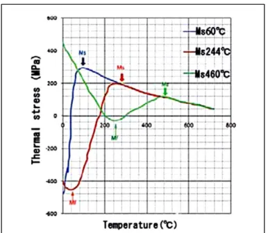
Phase diagrams show the equilibrium constituents of different alloys that are obtained at low heating and cooling rates. However, to form martensitic stainless steels, the alloy shouldn’t cool at the equilibrium conditions. For example, the phase diagram indicated that at ~1450°C, the liquid solidifies to δ-ferrite, then at ~1230°C, δ-ferrite transforms to γ. Consequently, at ~700°C, γ →α′ phase transformation occurs and α phase remains stable at room temperature. Actually, during welding, the alloy is supercooled, and other phases and microstructures may form, such as martensite, which is not predictable by the phase diagram. The other phases in martensitic stainless steels, which cannot be predicted by the phase diagram is the retained austenite at room temperature that may remain from γ → α′ phase transformation. Applying PWHT including tempering at ~600°C, might also form a finely dispersed reversed austenite in which tends to increase the toughness (Niederau, 1982). These phases that are present after welding are due to the non-equilibrium condition and aren’t accurately predicted by phase diagram, and the effect of the cooling rate on the microstructure may be investigated by means of a TTT diagram. An example of TTT diagram of 410 stainless steels is shown in Figure 2-8 (Atkins, 1980).
Figure 2-8 TTT diagram of 410 stainless steels (Atkins, 1980)
As Figure 2-8 shows, even at slow cooling rates, the final microstructure for the 410 stainless steel is predominantly martensite. By developing the steel manufacturing and producing a low carbon martensitic stainless steels, the nose of the transformation curve can be shifted to longer times in order to have martensite even at slow cooling rates.
2.2.3 Different zones in martensitic stainless steels weldment
Generally, the weld metal is exposed to the highest temperature during welding and on progress towards the HAZ, the temperature decreases until reaching the BM region where the microstructure is not affected. So, in the FZ the material is molten; however, in HAZ the transformations are in solid state. In fusion welding processes, the weldment is composed of three main zones including FZ, HAZ, and BM. The FZ of martensitic stainless steels contains predominantly martensite with up to 5% delta ferrite and up to 30% retained austenite that was observed in several studies with various welding processes (Carrouge, 2004; Enerhaug, 2001; Thibault, 2009). The fraction of each phase depends on the heat treatment of the as-received materials, chemical composition, PWHT, filler metal addition and welding process. The FZ micrograph of EB welded SMSS, as shown in Figure 2-9, reveals predominantly tempered martensite due to PWHT at 630°C ± 10°C for 30 min. Also a small amount of ferrite stringers are present.
Figure 2-9 Optical micrographs revealing tempered martensite in FZ: (a) with dendritic structure and (b) higher magnification of (a) (Srinivasan et al., 2004)
The HAZ of this group of materials can be divided to several zones based on the different microstructure and phases, distinctive microhardness values and various responses to the etchant. Srinivasan observed distinct HAZs in 20 mm thick EB welded SMSS, as shown in Figure 2-10 (Srinivasan et al., 2004) which were in agreement with other researchers who used other welding processes, such as FCAW (Thibault, 2009) and GTAW (Carrouge, 2004; Enerhaug, 2001). However, it’s noteworthy that these HAZs were identified differently in various research studies. The different regions of the HAZ in the EB weld of Srinivasan’s study were referred to as coarse-grained HAZ (CGHAZ) adjacent to the fusion boundary, fine-grained HAZ (FGHAZ) and HAZ next to the BM, as shown in Figure 2-10.
Figure 2-10 Optical micrographs of the EB SMSS weldment: (a) FZ and 3 HAZs, (b) FGHAZ and HAZ, (c) CGHAZ and
FGHAZ at higher magnification, (d) HAZ zone adjacent to BM at higher magnification (Srinivasan et al., 2004)
Considering previous findings on the microstructural evolution of the welded SMSS, the maximum number of regions that were recognized was in GTAW process performed by Enerhauge (Enerhaug, 2001) who described 5 distinct regions in the HAZs, HAZ1-5. Other researchers (Carrouge, 2004; Thibault, 2009) were unable to recognize HAZ1 and they defined only 4 HAZs in the weldment. In the present manuscript-based thesis, 4 HAZs were observed in the EB Weldment of the martensitic stainless steel and will be explained in Chapters 3 and 4. Based on the equilibrium phase diagram, as mentioned in previous section (Figure 2-6b), the HAZs of martensitic stainless steels can be divided into five distinctive zones (Enerhaug et al., 2001; Thibault et al., 2010) as below:
• Zone I: partially melted zone adjacent to fusion boundary that contains newly formed delta ferrite during heating.
• Zone II: completely transformation to delta ferrite on heating with significant grain growth and also referred to as coarse-grained HAZ or CG-HAZ.
• Zone III: partial transformation of austenite to delta ferrite on heating, and referred to as the high temperature dual-phase region.
• Zone IV: complete transformation of martensite to austenite on heating.
• Zone V: partial transformation of martensite to austenite on heating, and referred to as low temperature dual-phase region.
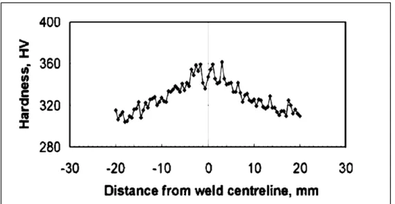
The microhardness evolution (Enerhaug et al., 2001; Thibault et al., 2010) proved the presence of various HAZs with the related microstructures. The microhardness profile in SMSS (Srinivasan et al., 2004) after PWHT is illustrated in Figure 2-11 and showed a maximum hardness value of 362 HV in the HAZ at a distance of about 5 mm from the weld centerline (adjacent to CGHAZ toward the BM) (Srinivasan et al., 2004).
Figure 2-11 Microhardness profile of the SMSS EB weld cross section after PWHT (Srinivasan et al., 2004) 2.2.4 Tensile properties in martensitic stainless steels
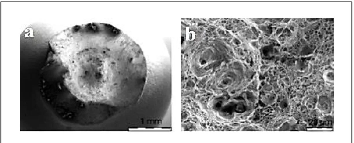
The cyclic stress induced by a turbine runner may lead to cracking in the components, thus the strength of the materials used in turbine runners has a significant effect on fatigue and rupture resistance. Generally, materials which have yield and ultimate strengths very close to each other, may fail in a brittle manner. Therefore, tensile properties must be considered as an important factor in material and weld metal selections for turbine runners. Commonly, the tensile properties mean the global tensile properties that depend on the failure zone of the weldment and may have a combination of BM, FZ, and HAZ properties. On the other hand, the global tensile properties only determine the properties at failure location which is affected by other zones. For instance, if the failure location is in BM, global properties are mostly related to the BM as well as the effects of the FZ or HAZs which are located outside of the failure location. Tensile fractographs of the EB welded SMSS (Srinivasan et al., 2004), as illustrated in Figure 2-12, showed the typical ductile fracture with dimple structure.
Figure 2-12 Fracture surface appearance of EB welded SMSS tested in air: (a) an overview of the fracture (showing the cup and cone fracture) and (b) fracture
surface showing dimples (Srinivasan et al., 2004)
The tensile samples of the EB weld failed in the BM and demonstrated lower ductility and tensile strength compared to BM which can be probably due to the composite-like structure of the tensile sample including FZ, HAZs, and BM. From global tensile test results, it can be concluded that the FZ tensile properties in EB welded SMSS are stronger than the BM tensile properties, but to understand the exact values it is necessary to test locally in different zones of the weldment.
Therefore, the idea of measuring the local tensile properties of each zone in the weldment developed to help understand the effect of different heat treatment conditions, welding properties and ductility in different locations of the weldment. By considering this idea, researchers interested in measuring local properties deliberately prepared miniature tensile samples which needed accurate machining and equipment (Cam et al., 1999). By developing technology and photography equipment, the DIC system was introduced as a new tool to measure the local properties during tensile testing (Abu et al., 2012; Dalgaard et al., 2012). By utilizing DIC, it becomes possible to measure the local tensile properties by only testing one tensile sample. To the best knowledge of the author, in spite of the availability of DIC for more than three decades, there hasn’t been any study about local properties of EB welded martensitic stainless steels without filler addition by only one pass.
2.3 Principles of DIC
DIC is an optical 2D or 3D non-contacting technique for measuring the surface displacements during mechanical testing and forming (Leclerc et al., 2009; Lockwood et Reynolds, 2003; Pan et al., 2009; Reynolds et Duvall, 1999). DIC requires capturing a set of images before (reference image) and after deformation (deformed image) from the measured surface which contain a random texture such as a speckle pattern (spraying black airbrush on white background) as shown in Figure 2-13. The speckle size, speckle density, type of algorithm, subset size, subset overlap, and gray level interpolation should be optimized obtain an accurate DIC results. Subsets are defined as small rectangular regions which consist of n╳n pixels in a reference image (Tang et al., 2012).
Figure 2-13 Speckle pattern on the measured surface
Basic theory of DIC that has been studied since 1980s (Ackermann, 1984; Leclerc et al., 2009; Moser et Lightner, 2007; Peters et Ranson, 1982), is to track a random gray pattern in a subset, between a reference image and a deformed image. The newer technique of DIC is 3D DIC method that is based on the stereovision system (Orteu et al., 2011) and utilizes two cameras from different angles at the same time to capture the 2D images at the same area of the object as shown in Figure 2-14. The calibration of cameras to determine the position and orientation of the camera and focal length of the lenses (Hild et Roux, 2006) are essential to have accurate results. The 3D contours of strain are then obtained using the best combination of two CCD cameras to match each point of the deformed images. As shown in Figure 2-15, points of each camera in a given stage are matched together in order to be a physical point. This matching procedure is called stereo match. Then, each point of the reference image and deformed image are matched together, which is called temporal match. After all matching processes are finished, 3D coordinates of all the point can be obtained through triangulation method using stereo and temporal matches. By comparing the coordinates of each point in
each stage with the reference stage, the displacement of that point can be calculated at the stage of interest (Bornert et al., 2009).
Figure 2-14 Typical schematic of the 3D DIC technique.
Figure 2-15 Schematic illustration of matching procedures of the 3D DIC
(Tang et al., 2012)
The 3D DIC methodology with two cameras and stereo-vision has been developed in different studies (Grytten et al., 2009; Kabir et al., 2012; Reynolds et Duvall, 1999; Wanjara et al., 2014) for various welded materials in order to determine full-field displacements during uniaxial tensile tests on the weldment as a heterogeneous material including FZ, HAZ, and BM. Utilizing two cameras provide the ability of observing the surface from different
directions and finding a 3D coordinate of any point. By comparing the changes between a reference images and series of images taken after load is applied, full-field three-dimensional displacements can be measured. This methodology has the advantage of determining the local properties of each zone of the weldment with minimum equipment along with a good repeatability and reliability of results.
2.3.1 Application of 3D DIC for local tensile properties in welded samples
Generally, the global strength of the weld depends on the distribution of properties across the different zones of the weldment including FZ, HAZ, and BM. Thus, weldment can be considered as a composite-like structure with distinct local properties. For many years mechanical characterisation of the weld has been addressed by the global properties of the weldment, however these global properties may not be a good representative for different locations across the weldment. Also, for achieving the local properties it was needed to extract miniature samples from each zone in order to characterize the weldment locally. Presently, by improving the imaging system such as DIC, there is possibility to use one standard sample and simultaneously obtain local properties in different zones. The 3D DIC has been increasingly used for close to 20 years as a very applicable tool for displacement measurements (Reynolds et Duvall, 1999) of mechanical testing such as tensile testing providing the local stress–strain curves across the weldment (Kabir et al., 2012; Leitão et al., 2012; Wanjara et al., 2014).
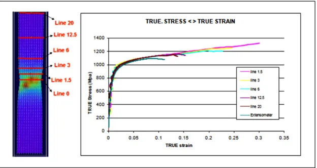
As abovementioned, the DIC can provide the local stress-strain curves with considering different gage lengths. Contrary to DIC, the extensometer usually used in tensile testing can only determine the displacement of the whole length and consequently provides a single stress-strain curve. However by DIC, different gage lengths can be evaluated per single test. Research done by (PI et al., 2010) showed that the result of DIC was in good agreement with the curve measured by extensometer with the same gage lengths as shown in Figure 2-16. In addition, by considering different gage lengths of 1.5, 3, 6, 12.5, 20 mm (line1.5, line3, line6, line12.5, and line20); the local true stress-strain curves were displayed for various gage lengths. The gage length of the sample which calculated by extensometer was 50 mm and therefore, the difference between the curves calculated by extensometer and DIC can be
attributed to the difference in gage length between in extensometer measurement and DIC measurement. Different curves shown in Figure 2-16, demonstrated that by increasing the gage length toward the whole gage length of sample, the DIC curve approaches the extensometer curve.
Figure 2-16 True strain-stress curves calculated by extensometer and DIC with different gage lengths (PI et al., 2010).
To the best of author knowledge, there isn’t any study on the local properties of EB welded low carbon martensitic stainless steel. Thus, in the present manuscript-based thesis, the procedure used for measuring tensile properties is similar to aforementioned procedure, with a little difference that there is combination of FZ and HAZs in the EB welded low martensitic stainless steel at the middle of tensile samples. Therefore, for measuring the local properties of each zone, the gage length must be defined the same as each zone of interest. For example, for local properties of the FZ, the gage length shall establish the same as the length of FZ. Therefore, before testing, the tensile samples on the opposite side of speckles side were etched and then each zone including FZ and HAZs was carefully measured as will be described in detail in Chapter 4.