Processor Family, Desktop Intel
®
Pentium
®
Processor Family, and
Desktop Intel
®
Celeron
®
Processor
Family
Datasheet – Volume 1 of 2
roadmaps.
The products described may contain design defects or errors known as errata which may cause the product to deviate from published specifications. Current characterized errata are available on request.
Copies of documents which have an order number and are referenced in this document may be obtained by calling 1-800-548-4725 or visit http:// www.intel.com/design/literature.htm.
Intel technologies’ features and benefits depend on system configuration and may require enabled hardware, software or service activation. Learn more at http://www.intel.com/ or from the OEM or retailer.
No computer system can be absolutely secure.
Intel® Hyper-Threading Technology (Intel® HT Technology) is available on select Intel® Core™ processors. It requires an Intel® HT Technology enabled system. Consult your PC manufacturer. Performance will vary depending on the specific hardware and software used. Not available on Intel® Core™ i5-750. For more information including details on which processors support Intel® HT Technology, visit http://www.intel.com/info/hyperthreading. Intel® High Definition Audio (Intel® HD Audio) requires an Intel® HD Audio enabled system. Consult your PC manufacturer for more information. Sound quality will depend on equipment and actual implementation. For more information about Intel® HD Audio, refer to http://www.intel.com/ design/chipsets/hdaudio.htm.
Intel® 64 architecture requires a system with a 64-bit enabled processor, chipset, BIOS and software. Performance will vary depending on the specific hardware and software you use. Consult your PC manufacturer for more information. For more information, visit http://www.intel.com/
content/www/us/en/architecture-and-technology/microarchitecture/intel-64-architecture-general.html.
Intel® Virtualization Technology (Intel® VT) requires a computer system with an enabled Intel® processor, BIOS, and virtual machine monitor (VMM). Functionality, performance or other benefits will vary depending on hardware and software configurations. Software applications may not be compatible with all operating systems. Consult your PC manufacturer. For more information, visit http://www.intel.com/go/virtualization.
The original equipment manufacturer must provide TPM functionality, which requires a TPM-supported BIOS. TPM functionality must be initialized and may not be available in all countries.
For Enhanced Intel SpeedStep® Technology, see the Processor Spec Finder at http://ark.intel.com/ or contact your Intel representative for more information.
Intel® AES-NI requires a computer system with an AES-NI enabled processor, as well as non-Intel software to execute the instructions in the correct sequence. AES-NI is available on select Intel® processors. For availability, consult your reseller or system manufacturer. For more information, see http://software.intel.com/en-us/articles/intel-advanced-encryption-standard-instructions-aes-ni/.
Intel® Active Management Technology (Intel® AMT) should be used by a knowledgeable IT administrator and requires enabled systems, software, activation, and connection to a corporate network. Intel AMT functionality on mobile systems may be limited in some situations. Your results will depend on your specific implementation. Learn more by visiting Intel® Active Management Technology.
No computer system can provide absolute security under all conditions. Intel® Trusted Execution Technology (Intel® TXT) requires a computer with Intel® Virtualization Technology, an Intel TXT-enabled processor, chipset, BIOS, Authenticated Code Modules and an Intel TXT-compatible measured launched environment (MLE). Intel TXT also requires the system to contain a TPM v1.s. For more information, visit http://www.intel.com/technology/ security.
Requires a system with Intel® Turbo Boost Technology. Intel Turbo Boost Technology and Intel Turbo Boost Technology 2.0 are only available on select Intel® processors. Consult your PC manufacturer. Performance varies depending on hardware, software, and system configuration. For more information, visit https://www-ssl.intel.com/content/www/us/en/architecture-and-technology/turbo-boost/turbo-boost-technology.html. Intel® Advanced Vector Extensions (Intel® AVX) are designed to achieve higher throughput to certain integer and floating point operations. Due to varying processor power characteristics, utilizing AVX instructions may cause a) some parts to operate at less than the rated frequency and b) some parts with Intel® Turbo Boost Technology 2.0 to not achieve any or maximum turbo frequencies. Performance varies depending on hardware, software, and system configuration and you should consult your system manufacturer for more information. Intel® Advanced Vector Extensions refers to Intel® AVX, Intel® AVX2 or Intel® AVX-512. For more information on Intel® Turbo Boost Technology 2.0, visit https://www-ssl.intel.com/content/www/us/en/ architecture-and-technology/turbo-boost/turbo-boost-technology.html
Intel, Intel Core, Celeron, Pentium, Intel SpeedStep, and the Intel logo are trademarks of Intel Corporation in the U.S. and/or other countries. *Other names and brands may be claimed as the property of others.
Contents
Revision History...9
1.0 Introduction...10
1.1 Supported Technologies...11
1.2 Interfaces... 12
1.3 Power Management Support...12
1.4 Thermal Management Support...13
1.5 Package Support...13
1.6 Terminology...13
1.7 Related Documents... 16
2.0 Interfaces... 18
2.1 System Memory Interface... 18
2.1.1 System Memory Technology Supported...19
2.1.2 System Memory Timing Support... 20
2.1.3 System Memory Organization Modes... 21
2.2 PCI Express* Interface... 23
2.2.1 PCI Express* Support...23
2.2.2 PCI Express* Architecture... 24
2.2.3 PCI Express* Configuration Mechanism... 24
2.3 Direct Media Interface (DMI)... 26
2.4 Processor Graphics...28
2.5 Processor Graphics Controller (GT)...28
2.5.1 3D and Video Engines for Graphics Processing... 29
2.5.2 Multi Graphics Controllers Multi-Monitor Support... 31
2.6 Digital Display Interface (DDI)...31
2.7 Intel® Flexible Display Interface (Intel® FDI)...37
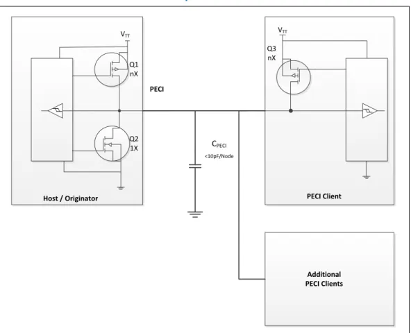
2.8 Platform Environmental Control Interface (PECI)... 37
2.8.1 PECI Bus Architecture...37
3.0 Technologies...39
3.1 Intel® Virtualization Technology (Intel® VT)... 39
3.2 Intel® Trusted Execution Technology (Intel® TXT)...43
3.3 Intel® Hyper-Threading Technology (Intel® HT Technology)... 44
3.4 Intel® Turbo Boost Technology 2.0...45
3.5 Intel® Advanced Vector Extensions 2.0 (Intel® AVX2)...45
3.6 Intel® Advanced Encryption Standard New Instructions (Intel® AES-NI)...46
3.7 Intel® Transactional Synchronization Extensions - New Instructions (Intel® TSX-NI)... 46
3.8 Intel® 64 Architecture x2APIC... 47
3.9 Power Aware Interrupt Routing (PAIR)...48
3.10 Execute Disable Bit...48
3.11 Supervisor Mode Execution Protection (SMEP)...48
4.0 Power Management... 49
4.1 Advanced Configuration and Power Interface (ACPI) States Supported... 50
4.2 Processor Core Power Management... 51
4.2.1 Enhanced Intel® SpeedStep® Technology Key Features...51
4.2.3 Requesting Low-Power Idle States...53
4.2.4 Core C-State Rules...54
4.2.5 Package C-States...55
4.2.6 Package C-States and Display Resolutions...59
4.3 Integrated Memory Controller (IMC) Power Management...60
4.3.1 Disabling Unused System Memory Outputs...60
4.3.2 DRAM Power Management and Initialization...61
4.3.3 DRAM Running Average Power Limitation (RAPL) ...63
4.3.4 DDR Electrical Power Gating (EPG)... 63
4.4 PCI Express* Power Management...63
4.5 Direct Media Interface (DMI) Power Management... 63
4.6 Graphics Power Management...64
4.6.1 Intel® Rapid Memory Power Management (Intel® RMPM)...64
4.6.2 Graphics Render C-State...64
4.6.3 Intel® Graphics Dynamic Frequency... 64
5.0 Thermal Management... 65
5.1 Desktop Processor Thermal Profiles... 67
5.1.1 Processor (PCG 2013D and PCG 2014) Thermal Profile... 68
5.1.2 Processor (PCG 2013C) Thermal Profile...69
5.1.3 Processor (PCG 2013B) Thermal Profile...70
5.1.4 Processor (PCG 2013A) Thermal Profile...72
5.2 Thermal Metrology... 73
5.3 Fan Speed Control Scheme with Digital Thermal Sensor (DTS) 1.1... 73
5.4 Fan Speed Control Scheme with Digital Thermal Sensor (DTS) 2.0... 75
5.5 Thermal Specifications...76
5.6 Processor Temperature...78
5.7 Adaptive Thermal Monitor... 78
5.8 THERMTRIP# Signal... 81
5.9 Digital Thermal Sensor... 81
5.9.1 Digital Thermal Sensor Accuracy (Taccuracy)...82
5.10 Intel® Turbo Boost Technology Thermal Considerations...82
5.10.1 Intel® Turbo Boost Technology Power Control and Reporting...82
5.10.2 Package Power Control...83
5.10.3 Turbo Time Parameter... 84
6.0 Signal Description... 86
6.1 System Memory Interface Signals... 86
6.2 Memory Reference Compensation Signals...88
6.3 Reset and Miscellaneous Signals... 89
6.4 PCI Express* Interface Signals... 90
6.5 Display Interface Signals... 90
6.6 Direct Media Interface (DMI)... 90
6.7 Phase Locked Loop (PLL) Signals...91
6.8 Testability Signals...91
6.9 Error and Thermal Protection Signals...92
6.10 Power Sequencing Signals... 92
6.11 Processor Power Signals...93
6.12 Sense Signals... 93
6.13 Ground and Non-Critical to Function (NCTF) Signals...93
7.0 Electrical Specifications... 94
7.1 Integrated Voltage Regulator...94
7.2 Power and Ground Lands ... 94
7.3 VCC Voltage Identification (VID)... 94
7.4 Reserved or Unused Signals... 99
7.5 Signal Groups...99
7.6 Test Access Port (TAP) Connection... 101
7.7 DC Specifications... 101
7.8 Voltage and Current Specifications... 102
7.8.1 Platform Environment Control Interface (PECI) DC Characteristics... 107
7.8.2 Input Device Hysteresis... 108
8.0 Package Mechanical Specifications... 109
8.1 Processor Component Keep-Out Zone... 109
8.2 Package Loading Specifications... 109
8.3 Package Handling Guidelines... 110
8.4 Package Insertion Specifications...110
8.5 Processor Mass Specification...110
8.6 Processor Materials... 110
8.7 Processor Markings... 111
8.8 Processor Land Coordinates...111
8.9 Processor Storage Specifications... 113
Figures
1 Platform Block Diagram ... 11
2 Intel® Flex Memory Technology Operations... 21
3 PCI Express* Related Register Structures in the Processor... 25
4 PCI Express* Typical Operation 16 Lanes Mapping... 26
5 Processor Graphics Controller Unit Block Diagram... 29
6 Processor Display Architecture...32
7 DisplayPort* Overview... 33
8 HDMI* Overview... 34
9 PECI Host-Clients Connection Example... 38
10 Device to Domain Mapping Structures... 42
11 Processor Power States... 49
12 Idle Power Management Breakdown of the Processor Cores ...52
13 Thread and Core C-State Entry and Exit...53
14 Package C-State Entry and Exit... 57
15 Thermal Test Vehicle Thermal Profile for Processor (PCG 2013D and PCG 2014)...68
16 Thermal Test Vehicle Thermal Profile for Processor (PCG 2013C)...69
17 Thermal Test Vehicle Thermal Profile for Processor (PCG 2013B)...70
18 Thermal Test Vehicle Thermal Profile for Processor (PCG 2013A)...72
19 Thermal Test Vehicle (TTV) Case Temperature (TCASE) Measurement Location...73
20 Digital Thermal Sensor (DTS) 1.1 Definition Points... 74
21 Digital Thermal Sensor (DTS) Thermal Profile Definition...76
22 Package Power Control... 84
23 Input Device Hysteresis... 108
24 Processor Package Assembly Sketch...109
25 Processor Top-Side Markings... 111
26 Processor Package Land Coordinates... 112
Tables
1 Terminology... 13
2 Related Documents...16
3 Processor DIMM Support by Product...19
4 Supported UDIMM Module Configurations...19
5 Supported SO-DIMM Module Configurations (AIO Only)... 20
6 DDR3 / DDR3L System Memory Timing Support...20
7 PCI Express* Supported Configurations in Desktop Products...23
8 Processor Supported Audio Formats over HDMI*and DisplayPort*... 35
9 Valid Three Display Configurations through the Processor...36
10 DisplayPort and embedded DisplayPort* Resolutions for 1, 2, 4 Lanes – Link Data Rate of RBR, HBR, and HBR2...36
11 System States...50
12 Processor Core / Package State Support... 50
13 Integrated Memory Controller States...50
14 PCI Express* Link States... 50
15 Direct Media Interface (DMI) States... 51
16 G, S, and C Interface State Combinations ... 51
17 D, S, and C Interface State Combination...51
18 Coordination of Thread Power States at the Core Level... 53
19 Coordination of Core Power States at the Package Level... 56
20 Deepest Package C-State Available... 59
21 Desktop Processor Thermal Specifications... 66
22 Thermal Test Vehicle Thermal Profile for Processor (PCG 2013D and PCG 2014) ... 68
23 Thermal Test Vehicle Thermal Profile for Processor (PCG 2013C)...69
24 Thermal Test Vehicle Thermal Profile for Processor (PCG 2013B)...71
25 Thermal Test Vehicle Thermal Profile for Processor (PCG 2013A)...72
26 Digital Thermal Sensor (DTS) 1.1 Thermal Solution Performance Above TCONTROL... 75
27 Thermal Margin Slope... 76
28 Boundary Conditions, Performance Targets, and TCASE Specifications... 77
29 Intel® Turbo Boost Technology 2.0 Package Power Control Settings... 84
30 Signal Description Buffer Types... 86
31 Memory Channel A Signals...86
32 Memory Channel B Signals...87
33 Memory Reference and Compensation Signals... 88
34 Reset and Miscellaneous Signals... 89
35 PCI Express* Graphics Interface Signals... 90
36 Display Interface Signals... 90
37 Direct Media Interface (DMI) – Processor to PCH Serial Interface... 90
38 Phase Locked Loop (PLL) Signals... 91
39 Testability Signals...91
40 Error and Thermal Protection Signals...92
41 Power Sequencing Signals... 92
42 Processor Power Signals... 93
43 Sense Signals... 93
44 Ground and Non-Critical to Function (NCTF) Signals... 93
45 Processor Internal Pull-Up / Pull-Down Terminations... 93
46 Voltage Regulator (VR) 12.5 Voltage Identification... 95
47 Signal Groups... 99
48 Processor Core Active and Idle Mode DC Voltage and Current Specifications...102
49 Memory Controller (VDDQ) Supply DC Voltage and Current Specifications... 103
50 VCCIO_OUT, VCOMP_OUT, and VCCIO_TERM ... 104
51 DDR3 / DDR3L Signal Group DC Specifications...104
52 Digital Display Interface Group DC Specifications... 105
54 CMOS Signal Group DC Specifications...106
55 GTL Signal Group and Open Drain Signal Group DC Specifications... 106
56 PCI Express* DC Specifications...107
57 Platform Environment Control Interface (PECI) DC Electrical Limits...107
58 Processor Loading Specifications... 110
59 Package Handling Guidelines... 110
60 Processor Materials... 111
61 Processor Storage Specifications... 113
Revision History
Revision Description Date
001 • Initial Release June 2013
002
• Added Desktop 4th Generation Intel® Core™ i7-4771, i5-4440,
i5-4440S, i3-4340, i3-4330, i3-4330T, i3-4130, and i3-4130T processors
• Added Desktop Intel® Pentium® G3430, G3420, G3220,
G3420T, G3220T processors
• Updated Section 4.2.4, Core C-State Rules • Updated Section 4.2.5, Package C-States • Minor edits throughout for clarity
September 2013
003 • Minor edits throughout for clarity November 2013
004
• Added Desktop Intel® Celeron® G1830, G1820, and G1820T
processors
• Added Section 4.2.6, "Package C-States and Display Resolutions"
December 2013
005 • Updated Table 39, "Testability Signals" March 2014
006
• Added Desktop 4th Generation Intel® Core™ i7-4790, i7-4790S,
i7-4790T, i7-4785T, i5-4690, i5-4690S, i5-4690T, i5-4590, i5-4590S, i5-4590T, i5-4460, i5-4460S, i5-4460T, i3-4360, i3-4350, i3-4350T, i3-4150, i3-4150T processors
• Added Desktop Intel® Pentium® G3450, G3440, G3440T,
G3240, G3240T processors
• Added Desktop Intel® Celeron® G1850, G1840, G1840T
processors
• Added Section 5.5, Thermal Specifications
May 2014
007
• Added Desktop 4th Generation Intel® Core™ i7-4790K, i5 4690K
processors
• Added Desktop Intel® Pentium® G3258 processor June 2014
008
• Added Desktop 4th Generation Intel® Core™ i3-4370, i5
i3-4360T, i3-4160, i3-4160T processors
• Added Desktop Intel® Pentium® G3460, G3450T, G3250,
G3250T processor • Added PCG 2014
• Updated Table 21, Desktop Processor Thermal Specifications • Updaed Table 26, Digital Thermal Sensor (DTS) 1.1 Thermal
Solution Performance Above TCONTROL
• Updated Table 27, Thermal Margin Slope.
• Updated Table 28, Boundary Conditions, Performance Tagets, and TCASE Specifications.
• Updaed Table 48, Processor Core Active and Idle Mode DC Voltage and Current Specifications.
July 2014
009 • Added Figure 27, 2014 Processor Package Land/Pin SideComponents. July 2014
010
• Added Desktop 4th Generation Intel® Core™ i3-4370T, i3-4170,
i3-4170T processors
• Added Desktop Intel® Pentium® G3470, G3460T, G3260,
G3260T processor
1.0
Introduction
The Desktop 4th Generation Intel® Core™ processor family , Desktop Intel® Pentium®
processor family, and Desktop Intel® Celeron® processor family are 64-bit, multi-core
processors built on 22-nanometer process technology.
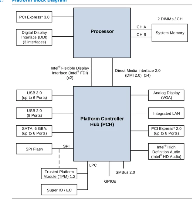
The processors are designed for a two-chip platform consisting of a processor and Platform Controller Hub (PCH). The processors are designed to be used with the Intel®
8 Series chipset. See the following figure for an example platform block diagram. Throughout this document, the Desktop 4th Generation Intel® Core™ processor family,
Desktop Intel® Pentium® processor family, and Desktop Intel® Celeron® processor
family may be referred to simply as "processor".
Throughout this document, the Desktop 4th Generation Intel® Core™ processor family
refers to the Desktop 4th Generation Intel® Core™ i7-4790, i7-4790S, i7-4790T,
i7-4790K, i7-4785T, i7-4771, i7-4770R, i7-4770K, i7-4770, i7-4770S, i7-4770T, i7-4765T, i5-4690, i5-4690S, i5-4690T, i5-4690K, i5-4670R, i5-4670K, i5-4670, i5-4670S, i5-4670T, i5-4670R, i5-4590, i5-4590S, i5-4590T, i5-4570R, i5-4570S, i5-4570T, i5-4570, i5-4460, i5-4460S, i5-4460T, i5-4440, i5-4440S, i5-4430,
i5-4430S, i3-4370, i3-4370T, i3-4360, i3-4360T, i3-4350, i3-4350T, i3-4340, i3-4330, i3-4330T, i3-4170, i3-4170T, i3-4150, i3-4160, i3-4160T, i3-4150T, i3-4130, and i3-4130T processors.
Throughout this document, the Desktop Intel® Pentium® processor family refers to
the Intel® Pentium® G3470, G3460, G3460T, G3450, G3450T, G3440, G3440T,
G3430, G3420, G3420T, G3258, G3260, G3260T, G3250, G3250T, G3240, G3240T, G3220, and G3220T processors.
Throughout this document, the Desktop Intel® Celeron® processor family refers to the
Intel® Celeron® G1850, G1840, G1840T, G1830, G1820, and G1820T processors.
Note: Some processor features are not available on all platforms. Refer to the processor Specification Update document for details.
Figure 1. Platform Block Diagram
Processor
PCI Express* 3.0 Digital Display Interface (DDI) (3 interfaces) System Memory 2 DIMMs / CH CH A CH BIntel® Flexible Display Interface (Intel® FDI)
(x2)
Direct Media Interface 2.0 (DMI 2.0) (x4)
Platform Controller
Hub (PCH)
SATA, 6 GB/s (up to 6 Ports) Analog Display (VGA) SPI Flash Super IO / EC Trusted Platform Module (TPM) 1.2 LPC Intel® High Definition Audio (Intel® HD Audio) Integrated LAN USB 3.0 (up to 6 Ports) USB 2.0 (8 Ports) PCI Express* 2.0 (up to 8 Ports) SPI SMBus 2.0 GPIOsSupported Technologies
• Intel® Virtualization Technology (Intel® VT)
• Intel® Active Management Technology 9.5 (Intel® AMT 9.5 )
• Intel® Trusted Execution Technology (Intel® TXT)
• Intel® Streaming SIMD Extensions 4.2 (Intel® SSE4.2)
• Intel® Hyper-Threading Technology (Intel® HT Technology)
• Intel® 64 Architecture
• Execute Disable Bit
• Intel® Turbo Boost Technology 2.0
1.1
• Intel® Advanced Vector Extensions 2.0 (Intel® AVX2)
• Intel® Advanced Encryption Standard New Instructions (Intel® AES-NI)
• PCLMULQDQ Instruction
• Intel® Secure Key
• Intel® Transactional Synchronization Extensions - New Instructions (Intel®
TSX-NI)
• PAIR – Power Aware Interrupt Routing
• SMEP – Supervisor Mode Execution Protection
• Enhanced Intel® Speedstep® Technology
Note: The availability of the features may vary between processor SKUs.
Interfaces
The processor supports the following interfaces:
• DDR3/DDR3L
• Direct Media Interface (DMI) • Digital Display Interface (DDI)
• PCI Express*
Power Management Support
Processor Core
• Full support of ACPI C-states as implemented by the following processor C-states: — C0, C1, C1E, C3, C6, C7
• Enhanced Intel SpeedStep® Technology
System • S0, S3, S4, S5 Memory Controller • Conditional self-refresh • Dynamic power-down PCI Express*
• L0s and L1 ASPM power management capability
DMI
• L0s and L1 ASPM power management capability
Processor Graphics Controller
• Intel® Rapid Memory Power Management (Intel® RMPM)
• Intel® Smart 2D Display Technology (Intel® S2DDT)
• Graphics Render C-state (RC6)
1.2
• Intel® Seamless Display Refresh Rate Switching with eDP port
• Intel® Display Power Saving Technology (Intel® DPST)
Thermal Management Support
• Digital Thermal Sensor
• Adaptive Thermal Monitor
• THERMTRIP# and PROCHOT# support
• On-Demand Mode
• Memory Open and Closed Loop Throttling
• Memory Thermal Throttling
• External Thermal Sensor (TS-on-DIMM and TS-on-Board)
• Render Thermal Throttling
• Fan speed control with DTS
Package Support
The processor socket type is noted as LGA1150. The package is a 37.5 x 37.5 mm Flip Chip Land Grid Array (FCLGA 1150). See the appropriate Processor Thermal
Mechanical Design Guidelines and LGA1150 Socket Application Guide for complete details on the package.
Terminology
Table 1. Terminology
Term Description
APD Active Power-down
B/D/F Bus/Device/Function
BGA Ball Grid Array
BLC Backlight Compensation
BLT Block Level Transfer
BPP Bits per pixel
CKE Clock Enable
CLTM Closed Loop Thermal Management DDI Digital Display Interface
DDR3 Third-generation Double Data Rate SDRAM memory technology
DLL Delay-Locked Loop
DMA Direct Memory Access
DMI Direct Media Interface
DP DisplayPort*
DTS Digital Thermal Sensor
continued...
1.4
1.5
Term Description
DVI* Digital Visual Interface. DVI* is the interface specified by the DDWG (Digital DisplayWorking Group)
EC Embedded Controller
ECC Error Correction Code
eDP* embedded DisplayPort*
EPG Electrical Power Gating
EU Execution Unit
FMA Floating-point fused Multiply Add instructions
FSC Fan Speed Control
HDCP High-bandwidth Digital Content Protection HDMI* High Definition Multimedia Interface
HFM High Frequency Mode
iDCT Inverse Discrete Cosine Transform IHS Integrated Heat Spreader
GFX Graphics
GSA Graphics in System Agent GUI Graphical User Interface IMC Integrated Memory Controller Intel® 64
Technology 64-bit memory extensions to the IA-32 architecture Intel® DPST Intel Display Power Saving Technology
Intel® FDI Intel Flexible Display Interface
Intel® TSX-NI Intel Transactional Synchronization Extensions - New Instructions
Intel® TXT Intel Trusted Execution Technology
Intel® VT Intel Virtualization Technology. Processor virtualization, when used in conjunctionwith Virtual Machine Monitor software, enables multiple, robust independent software
environments inside a single platform.
Intel® VT-d
Intel Virtualization Technology (Intel VT) for Directed I/O. Intel VT-d is a hardware assist, under system software (Virtual Machine Manager or OS) control, for enabling I/O device virtualization. Intel VT-d also brings robust security by providing protection from errant DMAs by using DMA remapping, a key feature of Intel VT-d.
IOV I/O Virtualization
ISI Inter-Symbol Interference ITPM Integrated Trusted Platform Module LCD Liquid Crystal Display
LFM Low Frequency Mode. LFM is Pn in the P-state table. It can be read at MSR CEh[47:40].
LFP Local Flat Panel
LPDDR3 Low-Power Third-generation Double Data Rate SDRAM memory technology
MCP Multi-Chip Package
Term Description
MFM Minimum Frequency Mode. MFM is the minimum ratio supported by the processor andcan be read from MSR CEh [55:48]. MLE Measured Launched Environment
MLC Mid-Level Cache
MSI Message Signaled Interrupt MSL Moisture Sensitive Labeling MSR Model Specific Registers
NCTF Non-Critical to Function. NCTF locations are typically redundant ground or non-criticalreserved, so the loss of the solder joint continuity at end of life conditions will not affect the overall product functionality.
ODT On-Die Termination
OLTM Open Loop Thermal Management
PCG Platform Compatibility Guide (PCG) (previously known as FMB) provides a designtarget for meeting all planned processor frequency requirements.
PCH Platform Controller Hub. The chipset with centralized platform capabilities includingthe main I/O interfaces along with display connectivity, audio features, power management, manageability, security, and storage features.
PECI The Platform Environment Control Interface (PECI) is a one-wire interface thatprovides a communication channel between Intel processor and chipset components to external monitoring devices.
Ψ ca
Case-to-ambient thermal characterization parameter (psi). A measure of thermal solution performance using total package power. Defined as (TCASE - TLA ) / Total
Package Power.
PEG PCI Express* Graphics. External Graphics using PCI Express* Architecture. It is ahigh-speed serial interface where configuration is software compatible with the existing PCI specifications.
PL1, PL2 Power Limit 1 and Power Limit 2
PPD Pre-charge Power-down
Processor The 64-bit multi-core component (package)
Processor Core The term “processor core” refers to Si die itself, which can contain multiple executioncores. Each execution core has an instruction cache, data cache, and 256-KB L2 cache. All execution cores share the L3 cache.
Processor Graphics Intel Processor Graphics
Rank A unit of DRAM corresponding to four to eight devices in parallel, ignoring ECC. Thesedevices are usually, but not always, mounted on a single side of a SO-DIMM. SCI System Control Interrupt. SCI is used in the ACPI protocol.
SF Strips and Fans
SMM System Management Mode
SMX Safer Mode Extensions
Storage Conditions
A non-operational state. The processor may be installed in a platform, in a tray, or loose. Processors may be sealed in packaging or exposed to free air. Under these conditions, processor landings should not be connected to any supply voltages, have any I/Os biased, or receive any clocks. Upon exposure to “free air” (that is, unsealed packaging or a device removed from packaging material), the processor must be handled in accordance with moisture sensitivity labeling (MSL) as indicated on the packaging material.
Term Description
SVID Serial Voltage Identification TAC Thermal Averaging Constant
TAP Test Access Point
TCASE The case temperature of the processor, measured at the geometric center of the top-side of the TTV IHS.
TCC Thermal Control Circuit TCONTROL
TCONTROL is a static value that is below the TCC activation temperature and used as a
trigger point for fan speed control. When DTS > TCONTROL, the processor must comply
to the TTV thermal profile.
TDP Thermal Design Power: Thermal solution should be designed to dissipate this targetpower level. TDP is not the maximum power that the processor can dissipate. TLB Translation Look-aside Buffer
TTV Thermal Test Vehicle. A mechanically equivalent package that contains a resistiveheater in the die to evaluate thermal solutions. TM Thermal Monitor. A power reduction feature designed to decrease temperature afterthe processor has reached its maximum operating temperature. VCC Processor core power supply
VDDQ DDR3/DDR3L power supply.
VF Vertex Fetch
VID Voltage Identification
VS Vertex Shader
VLD Variable Length Decoding VMM Virtual Machine Monitor
VR Voltage Regulator
VSS Processor ground
x1 Refers to a Link or Port with one Physical Lane x2 Refers to a Link or Port with two Physical Lanes x4 Refers to a Link or Port with four Physical Lanes x8 Refers to a Link or Port with eight Physical Lanes x16 Refers to a Link or Port with sixteen Physical Lanes
Related Documents
Table 2. Related Documents
Document Document
Number / Location Desktop 4th Generation Intel® Core® Processor Family, Desktop Intel® Pentium®
Processor Family, and Desktop Intel® Celeron® Processor Family Datasheet, Volume
2 of 2 328898
Desktop 4th Generation Intel® Core® Processor Family, Desktop Intel® Pentium®
Processor Family, and Desktop Intel® Celeron® Processor Family Specification
Update 328899
continued...
1.7
Document Document Number / Location Desktop 4th Generation Intel® Core® Processor Family, Desktop Intel® Pentium®
Processor Family, Desktop Intel® Celeron® Processor Family, and Intel® Xeon®
Processor E3-1200 v3 Product Family Thermal Mechanical Design Guidelines 328900
LGA1150 Socket Application Guide 328999
Intel® 8 Series / C220 Series Chipset Family Platform Controller Hub (PCH)
Datasheet 328904
Intel® 8 Series / C220 Series Chipset Family Platform Controller Hub (PCH)
Specification Update 328905
Intel® 8 Series / C220 Series Chipset Family Platform Controller Hub (PCH) Thermal
Mechanical Specifications and Design Guidelines 328906
Intel® 9 Series Chipset Family Platform Controller Hub (PCH) Datasheet 330550
Intel® 9 Series Chipset Family Platform Controller Hub (PCH) Specification Update 330551
Intel® 9 Series Chipset Family Platform Controller Hub (PCH) Thermal Mechanical
Specifications and Design Guidelines 330549
Advanced Configuration and Power Interface 3.0 http://www.acpi.info/
PCI Local Bus Specification 3.0 http://www.pcisig.com/
specifications
PCI Express Base Specification, Revision 2.0 http://www.pcisig.com
DDR3 SDRAM Specification http://www.jedec.org
DisplayPort* Specification http://www.vesa.org
Intel® 64 and IA-32 Architectures Software Developer's Manuals
http:// www.intel.com/ products/processor/ manuals/index.htm
2.0
Interfaces
System Memory Interface
• Two channels of DDR3/DDR3L Unbuffered Dual In-Line Memory Modules (UDIMM)
or DDR3/DDR3L Unbuffered Small Outline Dual In-Line Memory Modules (SO-DIMM) with a maximum of two DIMMs per channel.
• Single-channel and dual-channel memory organization modes
• Data burst length of eight for all memory organization modes
• Memory data transfer rates of 1333 MT/s and 1600 MT/s
• 64-bit wide channels
• DDR3/DDR3L I/O Voltage of 1.5 V for Desktop
• The type of the DIMM modules supported by the processor is dependent on the
PCH SKU in the target platform:
— Desktop PCH platforms support non-ECC UDIMMs only — All In One platforms (AIO) support SO-DIMMs
• Theoretical maximum memory bandwidth of:
— 21.3 GB/s in dual-channel mode assuming 1333 MT/s — 25.6 GB/s in dual-channel mode assuming 1600 MT/s
• 1Gb, 2Gb, and 4Gb DDR3/DDR3L DRAM device technologies are supported
— Using 4Gb DRAM device technologies, the largest system memory capacity possible is 32 GB, assuming Dual Channel Mode with four x8 dual ranked DIMM memory configuration
• Up to 64 simultaneous open pages, 32 per channel (assuming 8 ranks of 8 bank devices)
• Processor on-die VREF generation for DDR DQ Read and Write as well as CMD/ADD
• Command launch modes of 1n/2n
• On-Die Termination (ODT)
• Asynchronous ODT
• Intel Fast Memory Access (Intel FMA): — Just-in-Time Command Scheduling — Command Overlap
— Out-of-Order Scheduling
System Memory Technology Supported
The Integrated Memory Controller (IMC) supports DDR3/DDR3L protocols with two independent, 64-bit wide channels each accessing one or two DIMMs. The type of memory supported by the processor is dependent on the PCH SKU in the target platform.
Note: The IMC supports a maximum of two DDR3/DDR3L DIMMs per channel; thus, allowing up to four device ranks per channel.
Note: The support of DDR3/DDR3L frequencies and number of DIMMs per channel is SKU dependent.
Table 3. Processor DIMM Support by Product
Processor Cores Package DIMM per Channel DDR3 / DDR3L
Dual Core uLGA 1 DPC 1333/1600
2 DPC 1333/1600
Quad Core uLGA 1 DPC 1333/1600
2 DPC 1333/1600
DDR3/DDR3L Data Transfer Rates:
• 1333 MT/s (PC3-10600)
• 1600 MT/s (PC3-12800)
AIO platform DDR3/DDR3L SO-DIMM Modules:
• Raw Card B – Single Ranked x8 unbuffered non-ECC
• Raw Card F – Dual Ranked x8 (planar) unbuffered non-ECC
Desktop platform UDIMM Modules:
• Raw Card A – Single Ranked x8 unbuffered non-ECC
• Raw Card B – Dual Ranked x8 unbuffered non-ECC
• Standard 1Gb, 2Gb, and 4Gb technologies and addressing are supported for x8
devices. There is no support for memory modules with different technologies or capacities on opposite sides of the same memory module. If one side of a memory module is populated, the other side is either identical or empty.
Table 4. Supported UDIMM Module Configurations
Raw Card Version
DIMM
Capacity DeviceDRAM Technology DRAM Organization DRAM# of Devices # of Physical Devices Ranks # of Row / Col Address Bits # of Banks Inside DRAM Page Size Desktop Platforms
Unbuffered / Non-ECC Supported DIMM Module Configurations
A 1 GB 1 Gb 128 M X 8 8 1 14/10 8 8K
continued...
2.1.1
Raw Card Version
DIMM
Capacity DeviceDRAM Technology DRAM Organization DRAM# of Devices # of Physical Devices Ranks # of Row / Col Address Bits # of Banks Inside DRAM Page Size B 2 GB 1 Gb 128 M X 8 16 2 14/10 8 8K 4 GB 2 Gb 256 M X 8 16 2 15/10 8 8K 4 GB 4 Gb 512 M X 8 8 1 15/10 8 8K 8 GB 4 Gb 512 M X 8 16 2 16/10 8 8K
Note: DIMM module support is based on availability and is subject to change.
Table 5. Supported SO-DIMM Module Configurations (AIO Only)
Raw Card
Version CapacityDIMM OrganizationDRAM # of DRAMDevices # of Row/ColAddress Bits Inside DRAM# of Banks Page Size
B 1 GB 128 M x 8 8 14/10 8 8K 2 GB 256 M x 8 8 15/10 8 8K 4 GB 512 M x 8 8 16/10 8 8K F 2 GB 128 M x 8 16 14/10 8 8K 4 GB 256 M x 8 16 15/10 8 8K 8 GB 512 M x 8 16 16/10 8 8K
Note: System memory configurations are based on availability and are subject to change.
System Memory Timing Support
The IMC supports the following DDR3/DDR3L Speed Bin, CAS Write Latency (CWL), and command signal mode timings on the main memory interface:
• tCL = CAS Latency
• tRCD = Activate Command to READ or WRITE Command delay
• tRP = PRECHARGE Command Period
• CWL = CAS Write Latency
• Command Signal modes = 1N indicates a new command may be issued every
clock and 2N indicates a new command may be issued every 2 clocks. Command launch mode programming depends on the transfer rate and memory
configuration.
Table 6. DDR3 / DDR3L System Memory Timing Support
Segment Transfer Rate
(MT/s) tCL (tCK) (tCK)tRCD (tCK)tRP (tCK)CWL DPC ModeCMD All segments 1333 8/9 8/9 8/9 7 1 1N/2N 2 2N 1600 10/11 10/11 10/11 8 1 1N/2N 2 2N
2.1.2
Note: System memory timing support is based on availability and is subject to change.
System Memory Organization Modes
The Integrated Memory Controller (IMC) supports two memory organization modes – single-channel and dual-channel. Depending upon how the DIMM Modules are
populated in each memory channel, a number of different configurations can exist. Single-Channel Mode
In this mode, all memory cycles are directed to a single-channel. Single-channel mode is used when either Channel A or Channel B DIMM connectors are populated in any order, but not both.
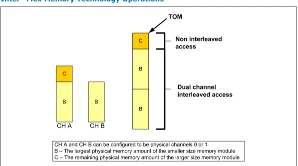
Dual-Channel Mode – Intel® Flex Memory Technology Mode
The IMC supports Intel Flex Memory Technology Mode. Memory is divided into
symmetric and asymmetric zones. The symmetric zone starts at the lowest address in each channel and is contiguous until the asymmetric zone begins or until the top address of the channel with the smaller capacity is reached. In this mode, the system runs with one zone of dual-channel mode and one zone of single-channel mode, simultaneously, across the whole memory array.
Note: Channels A and B can be mapped for physical channel 0 and 1 respectively or vice versa; however, channel A size must be greater or equal to channel B size. Figure 2. Intel® Flex Memory Technology Operations
CH B CH A B B C B B C Non interleaved access Dual channel interleaved access TOM
CH A and CH B can be configured to be physical channels 0 or 1
B – The largest physical memory amount of the smaller size memory module C – The remaining physical memory amount of the larger size memory module
Dual-Channel Symmetric Mode
Dual-Channel Symmetric mode, also known as interleaved mode, provides maximum performance on real world applications. Addresses are ping-ponged between the channels after each cache line (64-byte boundary). If there are two requests, and the second request is to an address on the opposite channel from the first, that request can be sent before data from the first request has returned. If two consecutive cache lines are requested, both may be retrieved simultaneously, since they are ensured to
be on opposite channels. Use Dual-Channel Symmetric mode when both Channel A and Channel B DIMM connectors are populated in any order, with the total amount of memory in each channel being the same.
When both channels are populated with the same memory capacity and the boundary between the dual channel zone and the single channel zone is the top of memory, the IMC operates completely in Dual-Channel Symmetric mode.
Note: The DRAM device technology and width may vary from one channel to the other.
System Memory Frequency
In all modes, the frequency of system memory is the lowest frequency of all memory modules placed in the system, as determined through the SPD registers on the memory modules. The system memory controller supports one or two DIMM connectors per channel. The usage of DIMM modules with different latencies is allowed, but in that case, the worst latency (among two channels) will be used. For dual-channel modes, both channels must have a DIMM connector populated and for single-channel mode only a single channel may have one or both DIMM connectors populated.
Note: In a two-DIMM Per Channel (2DPC) layout memory configuration, the furthest DIMM from the processor of any given channel must always be populated first.
Intel
®Fast Memory Access (Intel
®FMA) Technology Enhancements
The following sections describe the Just-in-Time Scheduling, Command Overlap, and Out-of-Order Scheduling Intel FMA technology enhancements.
Just-in-Time Command Scheduling
The memory controller has an advanced command scheduler where all pending requests are examined simultaneously to determine the most efficient request to be issued next. The most efficient request is picked from all pending requests and issued to system memory Just-in-Time to make optimal use of Command Overlapping. Thus, instead of having all memory access requests go individually through an arbitration mechanism forcing requests to be executed one at a time, the requests can be started without interfering with the current request allowing for concurrent issuing of
requests. This allows for optimized bandwidth and reduced latency while maintaining appropriate command spacing to meet system memory protocol.
Command Overlap
Command Overlap allows the insertion of the DRAM commands between the Activate, Pre-charge, and Read/Write commands normally used, as long as the inserted
commands do not affect the currently executing command. Multiple commands can be issued in an overlapping manner, increasing the efficiency of system memory protocol. Out-of-Order Scheduling
While leveraging the Just-in-Time Scheduling and Command Overlap enhancements, the IMC continuously monitors pending requests to system memory for the best use of bandwidth and reduction of latency. If there are multiple requests to the same open page, these requests would be launched in a back-to-back manner to make optimum use of the open memory page. This ability to reorder requests on the fly allows the IMC to further reduce latency and increase bandwidth efficiency.
2.1.3.1
Data Scrambling
The system memory controller incorporates a Data Scrambling feature to minimize the impact of excessive di/dt on the platform system memory VRs due to successive 1s and 0s on the data bus. Past experience has demonstrated that traffic on the data bus is not random and can have energy concentrated at specific spectral harmonics creating high di/dt, which is generally limited by data patterns that excite resonance between the package inductance and on die capacitances. As a result, the system memory controller uses a data scrambling feature to create pseudo-random patterns on the system memory data bus to reduce the impact of any excessive di/dt.
PCI Express* Interface
This section describes the PCI Express* interface capabilities of the processor. See the PCI Express Base* Specification 3.0 for details on PCI Express*.
PCI Express* Support
The PCI Express* lanes (PEG[15:0] TX and RX) are fully-compliant to the PCI Express Base Specification, Revision 3.0.
The processor with the PCH support the configurations shown in the following table (may vary depending on PCH SKUs).
Table 7. PCI Express* Supported Configurations in Desktop Products
Configuration Desktop
1x8, 2x4 GFX, I/O
2x8 GFX, I/O
1x16 GFX, I/O
• The port may negotiate down to narrower widths.
— Support for x16/x8/x4/x2/x1 widths for a single PCI Express* mode. • 2.5 GT/s, 5.0 GT/s and 8 GT/s PCI Express* bit rates are supported.
• Gen 1 Raw bit-rate on the data pins of 2.5 GT/s, resulting in a real bandwidth per pair of 250 MB/s given the 8b/10b encoding used to transmit data across this interface. This also does not account for packet overhead and link maintenance. Maximum theoretical bandwidth on the interface of 4 GB/s in each direction simultaneously, for an aggregate of 8 GB/s when x16 Gen 1.
• Gen 2 Raw bit-rate on the data pins of 5.0 GT/s, resulting in a real bandwidth per pair of 500 MB/s given the 8b/10b encoding used to transmit data across this interface. This also does not account for packet overhead and link maintenance. Maximum theoretical bandwidth on the interface of 8 GB/s in each direction simultaneously, for an aggregate of 16 GB/s when x16 Gen 2.
• Gen 3 raw bit-rate on the data pins of 8.0 GT/s, resulting in a real bandwidth per pair of 984 MB/s using 128b/130b encoding to transmit data across this interface. This also does not account for packet overhead and link maintenance. Maximum theoretical bandwidth on the interface of 16 GB/s in each direction simultaneously, for an aggregate of 32 GB/s when x16 Gen 3.
• Hierarchical PCI-compliant configuration mechanism for downstream devices. • Traditional PCI style traffic (asynchronous snooped, PCI ordering).
2.1.3.3
2.2
• PCI Express* extended configuration space. The first 256 bytes of configuration space aliases directly to the PCI Compatibility configuration space. The remaining portion of the fixed 4-KB block of memory-mapped space above that (starting at 100h) is known as extended configuration space.
• PCI Express* Enhanced Access Mechanism. Accessing the device configuration
space in a flat memory mapped fashion.
• Automatic discovery, negotiation, and training of link out of reset.
• Traditional AGP style traffic (asynchronous non-snooped, PCI-X Relaxed ordering). • Peer segment destination posted write traffic (no peer-to-peer read traffic) in
Virtual Channel 0: DMI -> PCI Express* Port 0
• 64-bit downstream address format, but the processor never generates an address above 64 GB (Bits 63:36 will always be zeros).
• 64-bit upstream address format, but the processor responds to upstream read transactions to addresses above 64 GB (addresses where any of Bits 63:36 are nonzero) with an Unsupported Request response. Upstream write transactions to addresses above 64 GB will be dropped.
• Re-issues Configuration cycles that have been previously completed with the Configuration Retry status.
• PCI Express* reference clock is 100-MHz differential clock.
• Power Management Event (PME) functions.
• Dynamic width capability.
• Message Signaled Interrupt (MSI and MSI-X) messages.
• Polarity inversion
Note: The processor does not support PCI Express* Hot-Plug.
PCI Express* Architecture
Compatibility with the PCI addressing model is maintained to ensure that all existing applications and drivers operate unchanged.
The PCI Express* configuration uses standard mechanisms as defined in the PCI Plug-and-Play specification. The processor PCI Express* ports support Gen 3. At 8 GT/s, Gen 3 operation results in twice as much bandwidth per lane as compared to Gen 2 operation. The 16 lanes PEG can operate at 2.5 GT/s, 5 GT/s, or 8 GT/s.
Gen 3 PCI Express* uses a 128b/130b encoding that is about 23% more efficient than the 8b/10b encoding used in Gen 1 and Gen 2.
The PCI Express* architecture is specified in three layers – Transaction Layer, Data Link Layer, and Physical Layer. See the PCI Express Base Specification 3.0 for details of PCI Express* architecture.
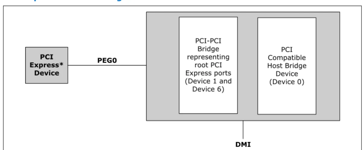
PCI Express* Configuration Mechanism
The PCI Express* (external graphics) link is mapped through a PCI-to-PCI bridge structure.
2.2.2
Figure 3. PCI Express* Related Register Structures in the Processor PCI-PCI Bridge representing root PCI Express ports (Device 1 and Device 6) PCI Compatible Host Bridge Device (Device 0) PCI Express* Device PEG0 DMI
PCI Express* extends the configuration space to 4096 bytes per-device/function, as compared to 256 bytes allowed by the conventional PCI specification. PCI Express* configuration space is divided into a PCI-compatible region (that consists of the first 256 bytes of a logical device's configuration space) and an extended PCI Express* region (that consists of the remaining configuration space). The PCI-compatible region can be accessed using either the mechanisms defined in the PCI specification or using the enhanced PCI Express* configuration access mechanism described in the PCI Express* Enhanced Configuration Mechanism section.
The PCI Express* Host Bridge is required to translate the memory-mapped PCI Express* configuration space accesses from the host processor to PCI Express* configuration cycles. To maintain compatibility with PCI configuration addressing mechanisms, it is recommended that system software access the enhanced
configuration space using 32-bit operations (32-bit aligned) only. See the PCI Express Base Specification for details of both the PCI-compatible and PCI Express* Enhanced configuration mechanisms and transaction rules.
PCI Express* Port
The PCI Express* interface on the processor is a single, 16-lane (x16) port that can also be configured at narrower widths. The PCI Express* port is being designed to be compliant with the PCI Express Base Specification, Revision 3.0.
PCI Express* Lanes Connection
Figure 4. PCI Express* Typical Operation 16 Lanes Mapping 0 1 2 3 4 5 6 7 8 9 10 11 12 13 14 15 1 X 16 C on tr ol le r Lane 0 0 1 2 3 4 5 6 7 8 9 10 11 12 13 14 15 Lane 1 Lane 2 Lane 3 Lane 4 Lane 5 Lane 6 Lane 7 Lane 8 Lane 9 Lane 10 Lane 11 Lane 12 Lane 13 Lane 14 Lane 15 0 1 2 3 4 5 6 7 1 X 8 C on tr ol le r 0 1 2 3 1 X 4 C on tr ol le r
Direct Media Interface (DMI)
Direct Media Interface (DMI) connects the processor and the PCH. Next generation DMI2 is supported.
Note: Only DMI x4 configuration is supported.
• DMI 2.0 support.
• Compliant to Direct Media Interface Second Generation (DMI2). • Four lanes in each direction.
• 5 GT/s point-to-point DMI interface to PCH is supported.
• Raw bit-rate on the data pins of 5.0 GB/s, resulting in a real bandwidth per pair of 500 MB/s given the 8b/10b encoding used to transmit data across this interface. Does not account for packet overhead and link maintenance.
• Maximum theoretical bandwidth on interface of 2 GB/s in each direction simultaneously, for an aggregate of 4 GB/s when DMI x4.
• Shares 100-MHz PCI Express* reference clock.
• 64-bit downstream address format, but the processor never generates an address above 64 GB (Bits 63:36 will always be zeros).
• 64-bit upstream address format, but the processor responds to upstream read transactions to addresses above 64 GB (addresses where any of Bits 63:36 are nonzero) with an Unsupported Request response. Upstream write transactions to addresses above 64 GB will be dropped.
• Supports the following traffic types to or from the PCH: — DMI -> DRAM
— DMI -> processor core (Virtual Legacy Wires (VLWs), Resetwarn, or MSIs only)
— Processor core -> DMI
• APIC and MSI interrupt messaging support:
— Message Signaled Interrupt (MSI and MSI-X) messages
• Downstream SMI, SCI and SERR error indication.
• Legacy support for ISA regime protocol (PHOLD/PHOLDA) required for parallel port DMA, floppy drive, and LPC bus masters.
• DC coupling – no capacitors between the processor and the PCH. • Polarity inversion.
• PCH end-to-end lane reversal across the link.
• Supports Half Swing “low-power/low-voltage”.
DMI Error Flow
DMI can only generate SERR in response to errors, never SCI, SMI, MSI, PCI INT, or GPE. Any DMI related SERR activity is associated with Device 0.
DMI Link Down
The DMI link going down is a fatal, unrecoverable error. If the DMI data link goes to data link down, after the link was up, then the DMI link hangs the system by not allowing the link to retrain to prevent data corruption. This link behavior is controlled by the PCH.
Downstream transactions that had been successfully transmitted across the link prior to the link going down may be processed as normal. No completions from
downstream, non-posted transactions are returned upstream over the DMI link after a link down event.
Processor Graphics
The processor graphics contains a generation 7.5 graphics core architecture. This enables substantial gains in performance and lower power consumption over previous generations. Up to 20 Execution Units are supported depending on the processor SKU. • Next Generation Intel Clear Video Technology HD Support is a collection of video
playback and enhancement features that improve the end user’s viewing experience
— Encode / transcode HD content
— Playback of high definition content including Blu-ray Disc* — Superior image quality with sharper, more colorful images
— Playback of Blu-ray* disc S3D content using HDMI (1.4a specification compliant with 3D)
• DirectX* Video Acceleration (DXVA) support for accelerating video processing — Full AVC/VC1/MPEG2 HW Decode
• Advanced Scheduler 2.0, 1.0, XPDM support
• Windows* 8, Windows* 7, OSX, Linux* operating system support
• DirectX* 11.1, DirectX* 11, DirectX* 10.1, DirectX* 10, DirectX* 9 support.
• OpenGL* 4.0, support
• Switchable Graphics support on AIO platforms with MxM solutions only
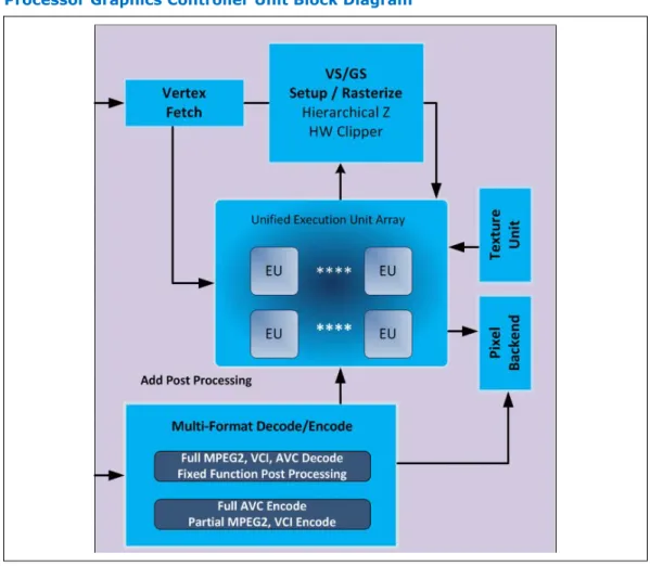
Processor Graphics Controller (GT)
The Graphics Engine Architecture includes 3D compute elements, Multi-format HW assisted decode/encode pipeline, and Mid-Level Cache (MLC) for superior high definition playback, video quality, and improved 3D performance and media. The Display Engine handles delivering the pixels to the screen. GSA (Graphics in System Agent) is the primary channel interface for display memory accesses and “PCI-like” traffic in and out.
2.4
Figure 5. Processor Graphics Controller Unit Block Diagram
3D and Video Engines for Graphics Processing
The Gen 7.5 3D engine provides the following performance and power-management enhancements.
3D Pipeline
The 3D graphics pipeline architecture simultaneously operates on different primitives or on different portions of the same primitive. All the cores are fully programmable, increasing the versatility of the 3D Engine.
3D Engine Execution Units
• Supports up to 20 EUs.The EUs perform 128-bit wide execution per clock. • Support SIMD8 instructions for vertex processing and SIMD16 instructions for
pixel processing. Vertex Fetch (VF) Stage
The VF stage executes 3DPRIMITIVE commands. Some enhancements have been included to better support legacy D3D APIs as well as SGI OpenGL*.
Vertex Shader (VS) Stage
The VS stage performs shading of vertices output by the VF function. The VS unit produces an output vertex reference for every input vertex reference received from the VF unit, in the order received.
Geometry Shader (GS) Stage
The GS stage receives inputs from the VS stage. Compiled application-provided GS programs, specifying an algorithm to convert the vertices of an input object into some output primitives. For example, a GS shader may convert lines of a line strip into polygons representing a corresponding segment of a blade of grass centered on the line. Or it could use adjacency information to detect silhouette edges of triangles and output polygons extruding out from the edges.
Clip Stage
The Clip stage performs general processing on incoming 3D objects. However, it also includes specialized logic to perform a Clip Test function on incoming objects. The Clip Test optimizes generalized 3D Clipping. The Clip unit examines the position of
incoming vertices, and accepts/rejects 3D objects based on its Clip algorithm. Strips and Fans (SF) Stage
The SF stage performs setup operations required to rasterize 3D objects. The outputs from the SF stage to the Windower stage contain implementation-specific information required for the rasterization of objects and also supports clipping of primitives to some extent.
Windower / IZ (WIZ) Stage
The WIZ unit performs an early depth test, which removes failing pixels and eliminates unnecessary processing overhead.
The Windower uses the parameters provided by the SF unit in the object-specific rasterization algorithms. The WIZ unit rasterizes objects into the corresponding set of pixels. The Windower is also capable of performing dithering, whereby the illusion of a higher resolution when using low-bpp channels in color buffers is possible. Color dithering diffuses the sharp color bands seen on smooth-shaded objects. Video Engine
The Video Engine handles the non-3D (media/video) applications. It includes support for VLD and MPEG2 decode in hardware.
2D Engine
The 2D Engine contains BLT (Block Level Transfer) functionality and an extensive set of 2D instructions. To take advantage of the 3D during engine’s functionality, some BLT functions make use of the 3D renderer.
Processor Graphics VGA Registers
The 2D registers consists of original VGA registers and others to support graphics modes that have color depths, resolutions, and hardware acceleration features that go beyond the original VGA standard.
Logical 128-Bit Fixed BLT and 256 Fill Engine
This BLT engine accelerates the GUI of Microsoft Windows* operating systems. The 128-bit BLT engine provides hardware acceleration of block transfers of pixel data for many common Windows operations. The BLT engine can be used for the following:
• Move rectangular blocks of data between memory locations
• Data alignment
• To perform logical operations (raster ops)
The rectangular block of data does not change, as it is transferred between memory locations. The allowable memory transfers are between: cacheable system memory and frame buffer memory, frame buffer memory and frame buffer memory, and within system memory. Data to be transferred can consist of regions of memory, patterns, or solid color fills. A pattern is always 8 x 8 pixels wide and may be 8, 16, or 32 bits per pixel.
The BLT engine expands monochrome data into a color depth of 8, 16, or 32 bits. BLTs can be either opaque or transparent. Opaque transfers move the data specified to the destination. Transparent transfers compare destination color to source color and write according to the mode of transparency selected.
Data is horizontally and vertically aligned at the destination. If the destination for the BLT overlaps with the source memory location, the BLT engine specifies which area in memory to begin the BLT transfer. Hardware is included for all 256 raster operations (source, pattern, and destination) defined by Microsoft*, including transparent BLT. The BLT engine has instructions to invoke BLT and stretch BLT operations, permitting software to set up instruction buffers and use batch processing. The BLT engine can perform hardware clipping during BLTs.
Multi Graphics Controllers Multi-Monitor Support
The processor supports simultaneous use of the Processor Graphics Controller (GT) and a x16 PCI Express* Graphics (PEG) device. The processor supports a maximum of 2 displays connected to the PEG card in parallel with up to 2 displays connected to the processor and PCH.
Note: When supporting Multi Graphics Multi Monitors, "drag and drop" between monitors and the 2x8PEG is not supported.
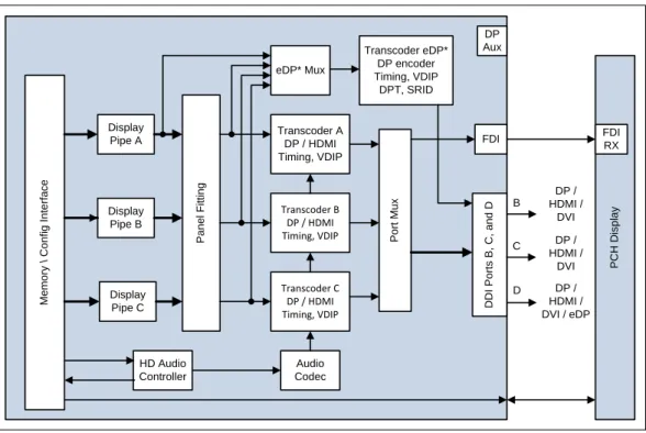
Digital Display Interface (DDI)
• The processor supports:
— Three Digital Display (x4 DDI) interfaces that can be configured as
DisplayPort*, HDMI*, or DVI. DisplayPort* can be configured to use 1, 2, or 4 lanes depending on the bandwidth requirements and link data rate of RBR (1.62 GT/s), HBR (2.7 GT/s) and HBR2 (5.4 GT/s). When configured as HDMI*, DDIx4 port can support 2.97 GT/s. In addition, Digital Port D ( x4 DDI) interface can also be configured to carry embedded DisplayPort* (eDPx4). Built-in displays are only supported on Digital Port D. — One dedicated Intel FDI Port for legacy VGA support on the PCH.
2.5.2
• The HDMI* interface supports HDMI with 3D, 4K, Deep Color, and x.v.Color. The DisplayPort* interface supports the VESA DisplayPort* Standard Version 1, Revision 2.
• The processor supports High-bandwidth Digital Content Protection (HDCP) for high-definition content playback over digital interfaces.
• The processor also integrates dedicated a Mini HD audio controller to drive audio on integrated digital display interfaces, such as HDMI* and DisplayPort*. The HD audio controller on the PCH would continue to support down CODECs, and so on. The processor Mini HD audio controller supports two High-Definition Audio streams simultaneously on any of the three digital ports.
• The processor supports streaming any 3 independent and simultaneous display
combination of DisplayPort*/HDMI*/DVI/eDP*/VGA monitors with the exception of 3 simultaneous display support of HDMI*/DVI . In the case of 3 simultaneous displays, two High Definition Audio streams over the digital display interfaces are supported.
• Each digital port is capable of driving resolutions up to 3840x2160 at 60 Hz through DisplayPort* and 4096x2304 at 24 Hz/2560x1600 at 60 Hz using HDMI*.
• DisplayPort* Aux CH, DDC channel, Panel power sequencing, and HPD are
supported through the PCH. Figure 6. Processor Display Architecture
M e m o ry \ C o n fi g I n te rf a c e Display Pipe A Display Pipe B Display Pipe C P a n e l F it ti n g HD Audio Controller Transcoder A DP / HDMI Timing, VDIP Transcoder B DP / HDMI Timing, VDIP Transcoder C DP / HDMI Timing, VDIP eDP* Mux Transcoder eDP* DP encoder Timing, VDIP DPT, SRID P o rt M u x Audio Codec DP Aux P C H D is p la y D D I P o rt s B , C , a n d D DP / HDMI / DVI DP / HDMI / DVI / eDP FDI FDI RX DP / HDMI / DVI D C B
Display is the presentation stage of graphics. This involves:
• Pulling rendered data from memory
• Converting raw data into pixels • Blending surfaces into a frame
• Organizing pixels into frames
• Optionally scaling the image to the desired size • Re-timing data for the intended target
• Formatting data according to the port output standard DisplayPort*
DisplayPort* is a digital communication interface that uses differential signaling to achieve a high-bandwidth bus interface designed to support connections between PCs and monitors, projectors, and TV displays. DisplayPort* is also suitable for display connections between consumer electronics devices, such as high-definition optical disc players, set top boxes, and TV displays.
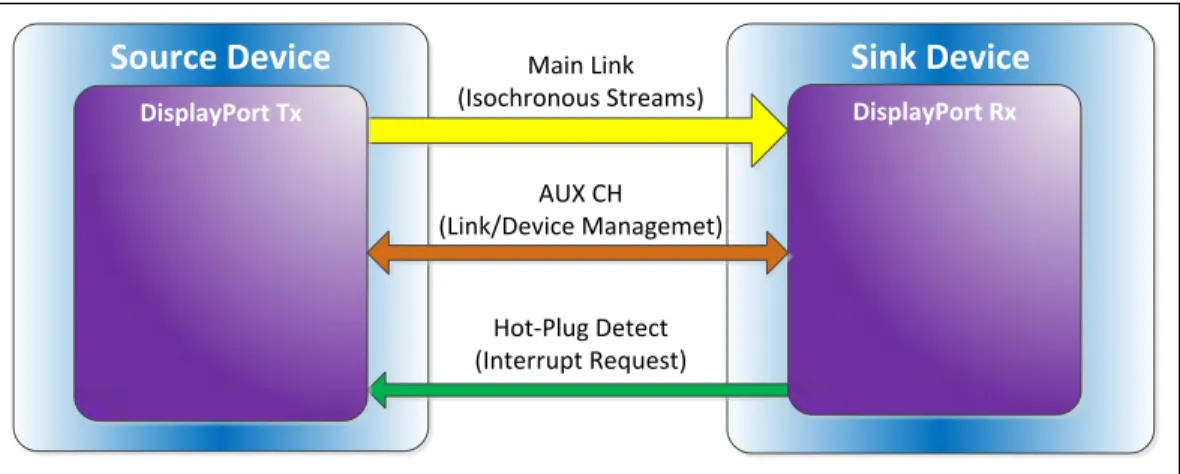
A DisplayPort* consists of a Main Link, Auxiliary channel, and a Hot-Plug Detect signal. The Main Link is a unidirectional, high-bandwidth, and low latency channel used for transport of isochronous data streams such as uncompressed video and audio. The Auxiliary Channel (AUX CH) is a half-duplex bidirectional channel used for link management and device control. The Hot-Plug Detect (HPD) signal serves as an interrupt request for the sink device.
The processor is designed in accordance with the VESA DisplayPort* Standard Version 1.2a. The processor supports VESA DisplayPort* PHY Compliance Test Specification 1.2a and VESA DisplayPort* Link Layer Compliance Test Specification 1.2a.
Figure 7. DisplayPort* Overview
Source Device
Main LinkSink Device
(Isochronous Streams) AUX CH (Link/Device Managemet) Hot-Plug Detect (Interrupt Request) DisplayPort Tx DisplayPort Rx
High-Definition Multimedia Interface (HDMI*)
The High-Definition Multimedia Interface* (HDMI*) is provided for transmitting uncompressed digital audio and video signals from DVD players, set-top boxes, and other audiovisual sources to television sets, projectors, and other video displays. It can carry high quality multi-channel audio data and all standard and high-definition consumer electronics video formats. The HDMI display interface connecting the processor and display devices uses transition minimized differential signaling (TMDS) to carry audiovisual information through the same HDMI cable.
HDMI includes three separate communications channels — TMDS, DDC, and the optional CEC (consumer electronics control). CEC is not supported on the processor. As shown in the following figure, the HDMI cable carries four differential pairs that
make up the TMDS data and clock channels. These channels are used to carry video, audio, and auxiliary data. In addition, HDMI carries a VESA DDC. The DDC is used by an HDMI Source to determine the capabilities and characteristics of the Sink.
Audio, video, and auxiliary (control/status) data is transmitted across the three TMDS data channels. The video pixel clock is transmitted on the TMDS clock channel and is used by the receiver for data recovery on the three data channels. The digital display data signals driven natively through the PCH are AC coupled and needs level shifting to convert the AC coupled signals to the HDMI compliant digital signals.
The processor HDMI interface is designed in accordance with the High-Definition Multimedia Interface with 3D, 4K, Deep Color, and x.v.Color.
Figure 8. HDMI* Overview
HDMI Source
HDMI Sink
TMDSDataChannel 0 Hot-Plug Detect HDMI Tx HDMI Rx TMDSDataChannel 1 TMDSDataChannel 2 TMDS Clock Channel
CEC Line (optional)
Display Data Channel (DDC)
Digital Video Interface
The processor Digital Ports can be configured to drive DVI-D. DVI uses TMDS for transmitting data from the transmitter to the receiver, which is similar to the HDMI protocol except for the audio and CEC. Refer to the HDMI section for more information on the signals and data transmission. To drive DVI-I through the back panel the VGA DDC signals are connected along with the digital data and clock signals from one of the Digital Ports. When a system has support for a DVI-I port, then either VGA or the DVI-D through a single DVI-I connector can be driven, but not both simultaneously. The digital display data signals driven natively through the processor are AC coupled and need level shifting to convert the AC coupled signals to the HDMI compliant digital signals.
embedded DisplayPort*
embedded DisplayPort* (eDP*) is an embedded version of the DisplayPort standard oriented towards applications such as notebook and All-In-One PCs. Digital Port D can be configured as eDP. Like DisplayPort, embedded DisplayPort also consists of a Main Link, Auxiliary channel, and an optional Hot-Plug Detect signal.
The eDP on the processor can be configured for 2 or 4 lanes.
The processor supports embedded DisplayPort* (eDP*) Standard Version 1.2 and VESA embedded DisplayPort* Standard Version 1.2.
Integrated Audio
• HDMI and display port interfaces carry audio along with video.
• Processor supports two DMA controllers to output two High Definition audio streams on two digital ports simultaneously.
• Supports only the internal HDMI and DP CODECs.
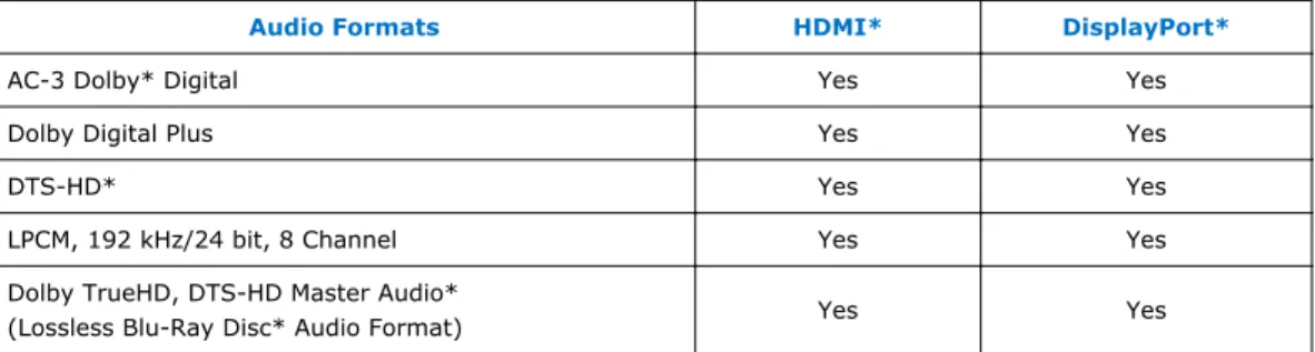
Table 8. Processor Supported Audio Formats over HDMI*and DisplayPort*
Audio Formats HDMI* DisplayPort*
AC-3 Dolby* Digital Yes Yes
Dolby Digital Plus Yes Yes
DTS-HD* Yes Yes
LPCM, 192 kHz/24 bit, 8 Channel Yes Yes
Dolby TrueHD, DTS-HD Master Audio*
(Lossless Blu-Ray Disc* Audio Format) Yes Yes
The processor will continue to support Silent stream. Silent stream is an integrated audio feature that enables short audio streams, such as system events to be heard over the HDMI and DisplayPort monitors. The processor supports silent streams over the HDMI and DisplayPort interfaces at 44.1 kHz, 48 kHz, 88.2 kHz, 96 kHz,
176.4 kHz, and 192 kHz sampling rates. Multiple Display Configurations
The following multiple display configuration modes are supported (with appropriate driver software):
• Single Display is a mode with one display port activated to display the output to one display device.
• Intel Display Clone is a mode with up to three display ports activated to drive the display content of same color depth setting but potentially different refresh rate and resolution settings to all the active display devices connected.
• Extended Desktop is a mode with up to three display ports activated to drive the content with potentially different color depth, refresh rate, and resolution settings on each of the active display devices connected.
The digital ports on the processor can be configured to support DisplayPort*/HDMI/ DVI. For Desktop designs, digital port D can be configured as eDPx4 in addition to dedicated x2 port for Intel FDI for VGA. The following table shows examples of valid three display configurations through the processor.
Table 9. Valid Three Display Configurations through the Processor
Display 1 Display 2 Display 3 Maximum Resolution Display 1 Maximum Resolution Display 2 Maximum Resolution Display 3 HDMI HDMI DP 4096x2304 @ 24 Hz 2560x1600 @ 60 Hz 3840x2160 @ 60 Hz DVI DVI DP 1920x1200 @ 60 Hz 3840x2160 @ 60 Hz DP DP DP 3840x2160 @ 60 Hz VGA DP HDMI 1920x1200 @ 60 Hz 3840x2160 @60 Hz 4096x2304 @ 24 Hz 2560x1600 @ 60 Hz eDP DP HDMI 3840x2160 @ 60 Hz 3840x2160 @60 Hz 4096x2304 @ 24 Hz 2560x1600 @ 60 Hz eDP DP DP 3840x2160 @ 60 Hz 3840x2160 @ 60 Hz
eDP HDMI HDMI 3840x2160 @ 60 Hz 4096x2304 @