Naoki Suzuki1, Asaki Hattori1, Makoto Hashizume2
1 Institute for High Dimensional Medical Imaging, The Jikei University School of Medicine,
4-11-1 Izumihoncho, Komae-shi, Tokyo, Japan {nsuzuki, hat}@jikei.ac.jp
2 Center for the Integration of Advanced Medicine and Innovative Technology, Kyushu
University Hospital, 3-1-1 Maidashi, Higashi-ku, Fukuoka, Japan [email protected]
Abstract. Various surgical robotics need augmented reality functions for the extension of their abilities. To enhance the benefit of augmented reality for robotic surgery, two research experiences are described. One is the loading of the augmented reality function onto the laparoscopic surgical robot. The results of the clinical case where the commercial surgical robot da Vinch loaded with augmented reality are described. The other is the endoscopic robot system which contained an augmented reality function. The results from an animal experiment where an EMR procedure on a pig was performed using augmented reality functions so that the location and direction of the robot’s tip, which is free to move in the stomach, are detailed.
1 Introduction
1-1 Augmented reality for surgery works
There are two reasons why the amount of research on navigation surgery using augmented reality technique and its clinical applications have recently increased. First is that the capability of computers has increased to the extent that they can now display accurate real-time 3D images of the internal parts of patients. In the past, only the larger computers or computers that specialized in displaying images could accomplish this task. But now, even the most standard type of lap-top computers can show 3D images that hold information that will satisfy clinical needs. This has moved navigation surgery closer to reality. Secondly, although we still need optical markers or plural registration points, the technology for detecting the position of the target in real-time has improved and the price of commercial equipment has become cheaper. This has resulted in an increase in the number of people doing applied research on navigation surgery[1-6].
control the surgical robot through a man-machine interface and can not see the operating field directly. Instead the vision is provided by a camera or some other optical system located near the operating field. Generally, the surgeon has to operate the surgical robot using this limited view compared with what is obtainable using the naked eye. Unfortunately, the detailed condition of the operation field and also the accurate direction of view are sometimes lost during this kind of operation. This happens frequently when an endoscopic surgical robot is used as it can bend its head to maneuver its robot arms and eyes (described in 2-2). That is, compared with other types of surgery such as open surgery or ordinary laparoscopic surgery, the robotic surgeon needs more information on the field of view. Safer and more rapid surgery can be achieved if the robotic surgeon has an indication of the targeted area or vessels near the operation field which were hidden from the real view. We describe the application of augmented reality technique for the laparoscopic robot and for the endoscopic robot, respectively, according to our research experience.
2 Method and results
2.1 Augmented reality for the laparoscopic robot (da Vinci)
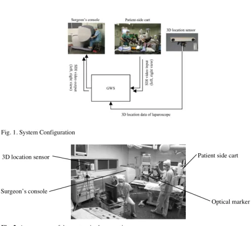
This augmented reality system is a combination of a commercial laparoscopic robot (da Vinci) and a developed augmented reality system (Figure 1). The da Vinci’s surgeon’s console system has a stereo display and handles that manipulate the robot arm on the patient side. The developed augmented reality system for this robot consists of two devices. One is the optical location sensor (POLARIS, Northern Digital, Inc.) that measures the location of the laparoscope. The other is a graphic workstation (GWS, OCTANE MXE, Silicon Graphics Inc.) that captures the laparoscopic image from the da Vinci system and superimposes 3D organ models to that image. The superimposed image is outputted to the stereo viewer of the surgeon's console as a stereo paired image in real time. The optical marker is attached away from the laparoscope’s tip so as not to interfere with the laparoscope’s movement. Using the data of the location sensor, the GWS transforms the coordinate system of the 3D organ model to the surgical field coordinate system and renders the 3D organ model image. Fig.2 shows the arrangement of these systems in the operating room.
Fig. 1. System Configuration
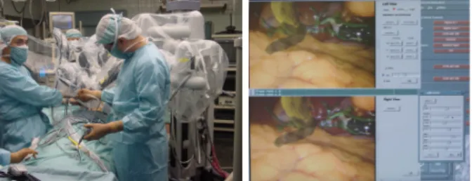
Fig. 2. Arrangement of the system in the operating room
For this system, we established following facilities. First, a display of organ models is updated in real-time following the movement of the laparoscope. Second, the surgeon is able to change the rendering style of the organ models according to the situation. Third, the system setup and calibration needs to be simple and quick to set up. Because the laparoscope needs to be sterilized, the location sensor marker can not be fixed to the laparoscope. Therefore, we attached the location sensor marker and calibrated the system just before the operation.
In order to fuse the laparoscope image and 3D organ models, the laparoscope and organ models coordinate system has to be transformed to a world coordinate system. After the laparoscope optical parameters were measured and registered the same locations on the organ model and the real organ, we calculated the transformation matrix for fusing the images. For the registration process, we measured four locations on the real organ by location sensor, and specified the same locations of the organ model on the GWS screen. Using the data from these locations, the transformation matrix was calculated.
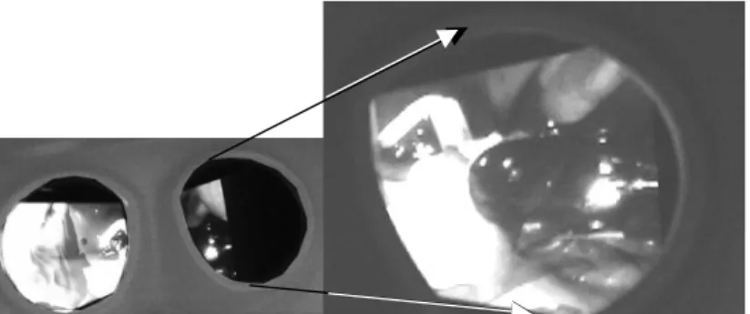
After the registration, the 3D organ model image is superimposed onto the laparoscope’s image. Figure 3 is the superimposed image of each (left and right) eye. Those 3D images are prepared for the cholecystectomy. The top window is the left eye's view and the bottom window is the right eye's view. Both are the view from under the liver. The gallbladder, common bile duct and hepatic duct model is
3D location sensor
Surgeon’s console
Patient side cart
change the organ model’s transparency and color for distinguishing the organ model from the laparoscope’s view.
Figure 4 shows a scene of the clinical experiment at a cholecystectomy. The superimposed image is shown in Figure 5. The gallbladder, common bile duct and hepatic duct model are superimposed onto the laparoscope’s surgical field image. The frame rate at this experiment was 7-9 fps for each eye respectively. Figure 6a and 6b show the surgeon's console displaying the superimposed image as a stereo paired image.
Fig. 3. Result images showing 3D organ models superimposed to the laparoscopic image; a: GWS display, top window: the left eye’s view, bottom window: the right eye’s view, b: a scene of the right eye’s viewer of the surgeon’s console
Fig. 4. A scene showing registration during a cholecystectomy (left). Superimposed images onto the GWS display (right). The patient’s organ models (gallbladder, common bile duct and hepatic duct) are superimposed onto the surgical field image; top window: the left eye’s view, bottom window: the right eye’s view
Fig. 5. Superimposed image on the surgeon’s console. a: a scene of the stereo viewer from surgeon’s console, b: a scene from the right eye’s viewer.
2-2 Augmented reality for an endoscopic robot
This system is composed of a developed endoscopic robot system and an augmented reality system. Figure 6 shows the system outline. The endoscopic robot system has a structure whose distal part of the elastic tube has endoscopic eyes and a pair of small sized two robot arms on the both side of the eye. The distal part of each arm has forceps shaped endo-effecter. A wire drive mechanism is applied to operate the robot arms. The diameter of a robot arm is 3 mm and the maximum size of the distal part of the robot is 21 mm so that it is able to reach the gastric tube via a esophagus. The component power of three stainless wires enclosed inside a thin elastic tube controls the endo-effecter. An endoscopist performs the operation of the endoscope shaped body of the robot to move it into the gastric tube, and a surgeon beside the endoscopist remotely controls both robot arms with the controller panel.
The augmented reality system consisted of two visual devices. One is a graphic workstation (GWS: OCTANE MXE, Silicon Graphics Inc.) that has a digital video processing board installed in it. The GWS captures the endoscopic video image and superimposes a 3D organ model onto the captured video image. The surgeon is able to watch the superimposed video on the endoscope’s monitor. One is the small magnetic location sensor (mini BIRD, Ascension Technology Co.) that always measures the location and the direction of the endoscopic robot’s tip. The sensor is fixed to the tip of the robot (Figure 6). Using the updated positional data from the location sensor, the GWS transforms the coordinate system of the 3D organ model to the surgical field coordinate system and renders the 3D organ model onto the endoscopic captured video image. The 3D organ models are previously reconstructed from the patient MRI or CT dataset.
Fig. 6. System outline (left). The appearance of the endoscopic robot when attached to a 3D location sensor (right).
Fig. 7. A scene from an animal experiment (the left monitor displays a normal endoscope view, the right monitor displays a superimposed endoscope view that has a navigation function)
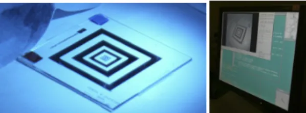
Fig. 8. Measurement of the endoscope’s optical parameters (a: the reference board that is captured by the GWS, b: the GWS display, the captured reference board image is processed on the GWS)
Figure 7 shows a scene from the animal experiment (A pig, total weight was 30 kg) for the verification of the developed system. First, we measured the endoscope’s optical parameters using the reference board (Figure 8). The captured reference board image was processed on the GWS, and the endoscope’s parameters were expressed numerically. Second, we registered the coordinate system of the surgical field and the 3D organ model. The surgeon pointed at the real body surface locations using the
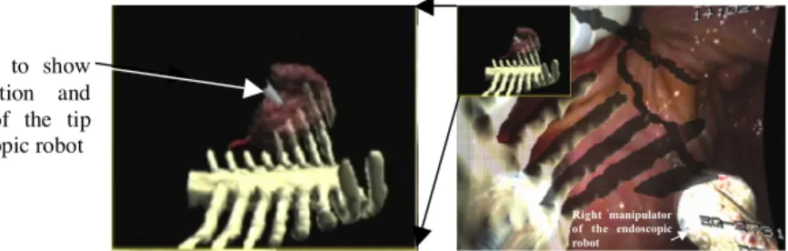
location sensor marker and specified the same locations on the 3D model on the GWS display. After registration, the surgeon inserted the endoscopic robot through the mouth cavity via the esophagus into the stomach. The 3D organ model that surrounded the stomach indicated the location and direction of the robot and was superimposed onto the endoscopic image (Figure 9). In this subjective image, the spine, ribs, liver and hepatic artery models were displayed. In this figure, the top left small window also shows an objective location of the robot’s tip in the coordinate system of the organ model. The viewpoint of this window could be set interactively. The surgeon was able to change the transparency and the color of the organ models and switch from superimposed video to non-superimposed video, depending on the situation of the surgical field. The frame rate for this experiment was 12-14 fps. In this verified experiment, EMR was performed using augmented reality technique. We made an ablation of a targeted gastric (5 cm in diameter) without perforation and severe bleeding. Wounds after the resection were closed using a clipping device, which was directed by a combined effort from the right and left manipulators.
Right manipulator of the endoscopic robot
Fig. 9. A superimposed image on the GWS display. (Organ models (spine, ribs and hepatic artery) are superimposed onto the endoscope’s image). Top left sub window shows the 3D location of the endoscope’s tip in the coordinate system of the organ models.
3 Conclusions and Future
We described the process of the loading of the augmented reality functions for robotic surgery. There are many advantages of the super imposed 3D image for future developments of this kind of system. First, there is no need to display all the volume data fully reconstructed from an acquired CT or MR scan for the rapid and easy recognition of the operation conditions. If all of the volume data acquired from measurements were overlaid at the time of the surgical operation, it would create a confusing display for the surgeons. Instead, there needs to be effective logic available so that excess data can be deleted effectively. There also needs to be an innovative display method so that structures which the surgeon wants will be distinctive in the operating field. In addition, there is a need to develop 3D positioning measurements without using engineering markers that need to be sterilized every time. If we can overcome these issues, we will be able to more easily capture the inner structure of the organ as it changes during the operation. One of the most desired things in augmented reality is the realization of technology which can update whole changes of
An arrow to show the direction and position of the tip of endoscopic robot
References
1.Devernay F, Mourgues F, Coste-Maniere E. Towards endoscopic augmented reality for robotically assistedminimally invasive cardiac surgery. Proc. of the International Workshop on Medical Imaging and Augmented Reality (MIAR2001); 16-20.
2.Birkfellner W, Figl M, Huber K, Watzinger F, Wanschitz F, Hummel J, Hanel R, Greimel W, Homolka P, Ewers R, Bergmann H. A head-mounted operating binocular for augmented reality visualization in medicine - design and initial evaluation. IEEE Trans. Med. Imag. 2002; 21(8): 991-7.
3.Shahidi R, Bax MR, Maurer CR Jr, Johnson JA, Wilkinson EP, Wang B, West JB, Citardi MJ, Manwaring KH, Khadem R. Implementation, calibration and accuracy testing of an image-enhanced endoscopy system. IEEE Trans. Med. Imag. 2002; 21(12): 1524-35. 4.Hattori A, Suzuki N, Hashizume M, Akahoshi T, Konishi K, Yamaguchi S, Shimada M,
Hayashibe M. A robotic surgery system (da Vinci) with image-guided function. Medicine Meets Virtual Reality 11 2003: 110-6.
5.Nicolau SA, Pennec X, Soler L, Ayache N. A Complete Augmented Reality GuidanceSystem for Liver Punctures: First Clinical Evaluation. MICCAI 2005, LNCS 3749, 539-47.
6.Giraldez JG, Caversaccio M, Pappas I, Kowal J, Rohrer U, Marti G, Baur C, Nolte LP, Ballester MAG. Design and clinical evaluation of an image-guided surgical microscope with an integrated tracking system. Int J CARS 2007; 1: 253-64.
7.Salisbury JK. The heart of microsurgery. Mechanical Engineering Magazine, ASME Int'l. 1998; 120(12): 47-51.
8.Reichenspurner H, Damiano RJ, Mack M, Boehm DH, Gulbins H, Detter C, Meiser B, Ellgass R, Reichart B. Use of the voice-controlled and computer-assisted surgical system ZEUS for endoscopic coronary artery bypass grafting. J Thorac Cardiovasc Surg 1999; 118: 11-6.
9.Guthart GS, Salisbury JK. The Intuitive Telesurgery System: Overview and Application. Proc. of the IEEE International Conference on Robotics and Automation (ICRA2000). San Francisco CA, April 2000.
10.Suzuki N, Sumiyama K, Hattori A, Ikeda K, Murakami EAY, Suzuki S, Hayashibe M, Otake Y, Tajiri H. Development of an endoscopic robotic system with two hands for various gastric tube surgeries. Medicine Meets Virtual Reality 11 2003: 349-53.