Research Journal
Volume 10, No. 30, June 2016, pages 84–88
DOI: 10.12913/22998624/62827 Research Article
SEISMIC BEHAVIOR OF BURIED PIPELINES SUBJECTED
TO NORMAL FAULT MOTION
Seyyed Ali Sabet1, Seyyed Mohammad Reza Nayyeri1
1 Department of Civil Engineering, Kashan Branch, Islamic Azad University, Kashan, Iran, e-mail: Sabet@ iaukashan.ac.ir
ABSTRACT
The one of the critical elements in infrastructure of today’s modern cities that cover large geographic distances is Network of buried pipelines. That is why they face a variety of natural hazards due to permanent ground replacements or wave emis-sions. Reports suggest that the main cause of damage to these lines is not seismic vibrations but large and permanent ground deformations are major causes of infra-structures’ demolition. Most recent studies are related to lines crossing the strike-slip faults, and only a few researchers have tried to study the behavior of structures against the normal fault. This article discusses the behavior and response of struc-tures and infrastrucstruc-tures against the movements of normal faults using the finite elements method. In this study, the interaction between soil-soil and soil-pipe has been considered in modeling terms.
Keywords: finite element method, interaction, normal fault, buried pipeline.
INTRODUCTION
Earthquake is a natural disaster that leaves a lot of life loses and property damages every year. In addition to the casualties and property loses in residential areas, earthquakes can have huge
in-dustrial, and environmental, financial impacts in
industrial areas. Researchers studied the behav-ior of these structures against the movements’ of faults using the analytical methods. But due to the use of simplifying assumptions the accuracy of responses was reduced [1]. Newmark and Hall
[1] were first to investigate the crossing of bur -ied pipelines. They considered lateral and axial deformation of pipe as the axial and lateral defor-mation of soil in their method, while they ignored the relative displacement between the soil and the pipes. Moreover, the model they delivered was applicable to pipes under traction and slip faults [1].Then in 1977, Kennedy et al. [2] developed Newmark and Hall model. In their model, they considered the interaction between the water and
the soil components [2].In recent years, finite
element methods have been booming more and more. For example, in 2001, Takada et al. [3] found out that pipes do not show shell behavior against the movement of fault, hence they mod-eled pipelines as shell elements. In 2011, Joshi et al.[4] analyzed pipes buried under reverse fault
displacement using a three-dimensional finite el -ement model. In this analysis pipe was studied by beam and soil elements and was modeled by using spring elements. Rafooii at al. [5] can be mentioned as one of the laboratory works
com-pared with the numerical results obtained from fi -nite element method. In his study, he investigated laboratory model of pipe buried under the normal fault movement. Then, using at
three-dimension-al finite element model, responses and results of
these two methods were surveyed and compared.
MODELING
This model has three main sections. Two sec-tions of soil are related to faults and one section
is related to pipe. Dimensions of the models made were chosen accurately, according to previous re-search and studies. A parametric study showed that a length of 60 times the diameter of the pipe in the longitudinal direction and the cube dimen-sions in height and lateral dimension equal to 10
and 5 times the pipe diameter is sufficient [6]. For
this reason, and given that the assumed diameter for the pipeline is equal to 0.9 meter the extent of the selected length, width and height for the model is respectively 80, 5, and 10.
Steel AIP5L-X65 is used for pipes.
More-over, due to the variety of different soils, two
kinds of soils, Sticky and non-sticky soil, were
used in this research. Technical specifications
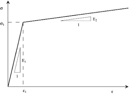
of soils used were presented in Table 2. Ram-berg – Osgood criteria is used for steel pipe-line. The stress-strain diagram of the given steel is shown in (Figure 1). The mechanical characteristics of the pipeline are presented in Table 1 Mohr-Coulomb elastic model is dedi-cated to Continuous element representing the soil around the pipe.
Table 1. Properties of AP15L-X65 pipe
Yield stress (σ1) 490 MPa
Failure stress (σ2) 531 MPa
Failure strain (ε2) 4.0%
Elastic Young’s modulus (E1) 210 GPa Yield strain (ε1 = σ1/E1) 0.233% Plastic Young’s modulus
(E2 = (σ2-σ1)/(ε2-ε1) 1.088 GPa
In the Table 2, according to Mohr-Coulomb criteria, the following signs are presented
respec-tively: (γ) is density, (E) is the Modulus of elastic
-ity, (ν) is the Poisson’s ratio, (φ) is the internal friction angle of soil, (ψ) is dilation angle, (C)
cohesion.
In this study interaction is specified as a sur -face to sur-face interaction. These sur-faces mean parts of two substances which are in contact with each other, so that these surfaces may be formed in any geometric shape [7].
Also, according to previous reports the
coef-ficient of friction between pipe and soil and ef -fective interaction between them is given by the equation (1):
(1)
The pipe’s internal pressure is also applied as a compressive force to the inner surfaces. Regard-ing the static motion of the fault movement, static displacement of each surface will be applied to the movable wall in order to simulate the movement of the fault completely. Also, the pipeline is a kind of shell element; it can be modeled by Four-node mesh (S4R). This element is used in large and non-linear deformations and follows Romberg Osgood relationship. Soil that is a kind of solid element is modeled with 6-sided 8-noded mesh (C3D8R). Having complex linear and nonlinear behavior, this element is suitable for plasticity and contact issues along with great deformations. After
select-ing the proper meshselect-ing, the smaller and finer mesh
is used in those areas due to stress concentration at
the confluence of the fault and pipes.
PARAMETRIC ANALYSIS
The forces of inertia caused by the mass of
pipes is insignificant, comparing with forces such
as hardness of soil and pipe system and the period
Table 2. Surrounding soil properties [8]
ν
E (MPa)
c (Kpa)
ψ φ
γ (KN/m3)
Soil type 0.35 25 50 0 0 18 Soft clay 0.35 100 200 0 0 18 Stiff clay 0.3 8 5 10 30 18 Loose granular 0.3 50 5 10 39 18 Dense granular
of the system is very small as well. Considering that the period of the system compared to the time of the displacement caused by fault is low, using static analysis in order to investigate the behavior of buried pipes against large faults movements would be logical. Besides, in researches conduct-ed so far, dynamic response is considerconduct-ed trivial and small Compared to the deformation caused by the fault [7]. Regarding the point mentioned in this article, it is assumed that nonlinear static
analysis offers acceptable result. In the other sec
-tion the following types of parameters affecting
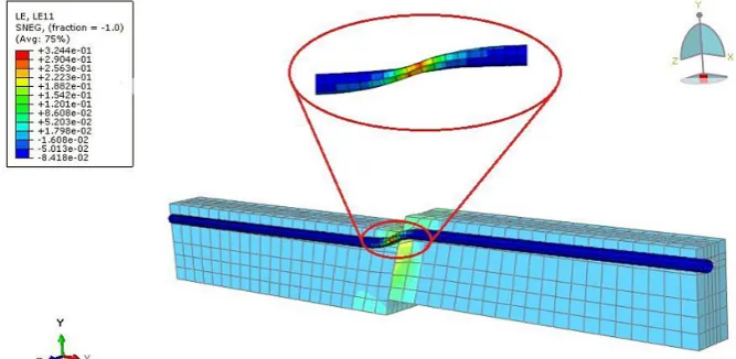
the pipeline’ response such as depth of the buried pipe, pipe thickness, pipe diameter, angle of in-clination of the fault, the type of soil around the pipe and soil internal friction angle are examined. Figure 2 shows the deformation and buckling the pipeline caused by the normal fault displacement.
The pipelines in the cohesive soils have the greatest impact compared to granular soils (Fig-ure 3).This is because of the larger central compo-nent of granular soils resistance. The extent of the
Fig. 2. The deformation and buckling in the pipeline caused by the normal fault displacement
Fig. 3. The effect of different types of soils on the axial strain of pipeline under the influence of the normal fault movement
Fig. 4. The effect of increase in the depth of burial pipeline under the influence of normal fault move
-ment in the loose granular soil
Fig. 6. The effect of the increase in the thicknesses of the pipe wall on the axial strain of pipeline under the influence of the normal fault movement in the loose granular soil
Fig. 7. The effect of the increase in the internal friction angle on the axial strain of pipeline under the influence of the normal fault movement in the loose granular soil
maximum strains in soft soils in both granular and cohesive ones is lower than the maximum strain in hard cohesive and granular soil.
By increasing the hardness of the soil around the pipeline the extent of the strain in the pile is increased as well. This can be assumed so that by reducing soil hardness compared to the hardness of the pipeline, interaction between the soil and the pipe is increased and this causes slip between the outer surfaces of the pipe and soil and reduces responses.
Figure 4 show that when the depth of the buried pipeline increases, axial strain increases as well. According to the results, we can say that with the rise of the burial depth, interaction
forc-es between soil and pipe is enhanced comparing with hardness of the pipeline and there by the re-sponse capacity of the piped is reduced.
In Figure 5, an increase in the diameter of the pipeline causes the reduction of the amount of ax-ial strain. Enhancing the pipe diameter increases
the flexural hardness of the pipe. The reason of reduction of axial strain is the reduction effect of increased flexural hardness of pipeline on the in -teraction between soil and pipe, which gradually leads into higher pipeline’s response capacity.
In the Figure 6, enhancement of the pipeline wall reduces axial strain in the pipeline. In oth-er words, by increasing the pipe wall thickness,
cross-sectional area and moment of inertia are in-creased as well. Therefore, levels of resistant an-chor is increased which in turn reduces the stress and strain in the pipeline.
According to the results of (Figure 7), it can be deduced that by increasing the angle of inter-nal friction the interaction between soil and pipe is also enhanced and this in turn increases the strain and stress in the pipeline.
The results of (Figure 8) show that with in-creasing normal fault angel the maximum axial
strain is decreased significantly. The reason is
reduction of central component of movement of
these faults that is having a significant impact on
results. So, the fault with higher angle, pipelines are much more vulnerable.
CONCLUSIONS
In this study was discussed the behavior and response of structures and infrastructures against
the movements of normal faults using the finite
elements method and the results are as follows: 1. In the fault area, pipelines with higher
thick-nesses and more formable materials should be
used and the use of reflective coatings to re -duce the interaction between the soil and the pipeline in the areas of fault is recommended. 2. Recommended in fault zones, smooth and cor-rosion resistant coatings used on the body of pipelines for reducing the friction between the soil and the body.
3. Given the very significant effect of soil type
on the response of these infrastructures, it is recommended to use loose granular soils at the
confluence of these pipes with faults.
4. The increasing the diameter of the pipeline will reduce the strain exerted on the pipeline and this will increase pipeline capacity and higher stability.
5. Reduction in the depth of the buried pipe-line increases pipepipe-line capacity; therefore, it is recommended to use lower burial depth as far as possible for the implementation of these structures considering environmental and geo-graphical conditions.
REFERENCES
1. Newmark N.M. and Hall W.J. Pipeline design to resist large fault displacement. Proceedings of U.S., national conference on earthquake engineer-ing, 1975, 416–425.
2. Kennedy R.P., Chow A.W. and Williamson R.A. Fault movement effects on buried oil pipeline. Transportation engineering journal of the American Society of Civil Engineers, 103(5), 1977, 617–633. 3. Takada S., Hassani N. and Fukuda K. A new pro-posal for simplified design of buried steel pipes crossing active faults. Earthquake engineering & structural dynamics, 30(8), 2001, 1243–1257. 4. Joshi S., Prashant A., Deb A. and Klain S. Analysis
of buried pipelines subjected to reverse fault mo-tion. Soil Dynamics and Earthquake Engineering, 31(7), 2011, 930–940.
5. Rofooei R, Hojat Jalali H, Atari N, Alavi M and Sa-madian M (). Assement of the Behaviour of Buried Gas Pipelines Subhect to Reverse Faulting, Pacific Earthquake Engineering Research Center (PEER), 2012, 105–117.
6. Vazouras P. and Karamanson S. Finite element anal-ysis of buried steel pipelines under strike-slip fault displacement, Journal of Soil Dynamics and Earth-quake Engineering, 30(11), 2010, 1361 –1376. 7. Bolvardi V. and Bakhshi A. A study on seismic
behavior of buried steel pipelines crossing active faults. ASCE, In Pipelines 2010@ sClimbing New Peaks to Infrastructure Reliability: Renew, Rehab, and Reinvest, 2010, 1–12.