INTRODUCTION
In recent decades, various techniques have been developed to store thermal energy [1, 2]. Such systems have a very high potential for use in thermal energy consuming equipment and, from an economic point of view, are a great alternative to helping large thermal energy consumers. The use of phase-changing material (PCM) in thermal storage tanks is very common. One of the benefits of these materials is high hidden energy, so they have capability of storing a lot of energy. One of the weaknesses of the phase-changing material is low thermal conductivity and therefore relatively low heat transfer. Square enclosures are one of the most commonly used enclosures to absorb solar energy by solar cells that absorb energy by phase-changing materials [3], the longer the melt-ing time or the so-called solar cell chargmelt-ing time, the thermal efficiency of this The solar cell will be better. Groulx [4] investigated a numerical study
for comparing the melting and freezing of the phase changing material with nanoparticles, the pure phase changing material, and the fin system, taking into account the same mass, they examined the effect of nanoparticles and observed that the problem The heat transfers by applying the phase changing material can be easily solved by using the easy and inexpensive method of using Fin as compared to nanoparticles. Gao et al. [5] inves-tigated the phase changing method using Leitz Boltzmann’s method inside porous environments in the presence of Fin. The results indicated that the melting rate increased significantly with the presence of Fin in a porous medium. Jung et al. [6] numerically investigated melting of phase chang-ing material in a fin tube. The results showed that, as the dominant mechanism of heat transfer in the melting of the phase changing material is natural convection, the use of Fins significantly improves the thermal performance. This phenomenon has been empirically investigated by the onset of
Application of Nanoparticles in the Process
of Phase Change Paraffin in a Chamber
As’ad Alizadeh
Department of Mechanical Engineering , College of Engineering , University of Zakho, Zakho City, Iraq e-mail: [email protected]
ABSTRACT
In this study, melting of a phase changing material enriched with nanoparticles in a circular ring-rectangular en-closure was investigated and the results were analyzed. At the beginning of the melting process in the absence of a natural displacement, the mechanism of conduction heat transfer around the hot cylinder is the dominant mecha-nism. Over time, natural displacement gradually appears and deforms the melting boundary above the cylinder.
Over time, when the thickness of the liquid phase grows, the thermal resistance increases, this can be verified by
reviewing the Nusselt chart. So this phenomenon reduces the rate of melting and temperature changes. The results show that increasing the nanoparticle volume fraction due to increased conductivity and decreasing latent heat causes an increase in the melting rate and the amount of energy absorbed. From the study of various volume frac-tions, it can be concluded that the use of a higher volume fraction of 3% is more appropriate both in terms of energy and in terms of the melting rate. However, it should be taken into account that if the melting rate exceeds this value,
it may cause agglomeration and deposition of nanoparticles and reducing system efficiency.
Keywords: aluminum oxide, phase change material, nusselt number, nanoparticles
Volume 13, Issue 3, September 2019, pages 113–119
https://doi.org/10.12913/22998624/110372
Research Journal
Accepted: 2019.08.15melting through homogeneous heating from one or more sides of the enclosure [7–11]. Zhang et al. [12] presented experimental results of the melting process of n-octadecane material in a rectangular enclosure under constant thermal flux conditions. The results show that natural convection has an important effect on the evolution of the solid-liquid interface, and this effect will be more dra-matic by increasing the Rayleigh and Stefan num-bers. Jianhua et al. [13] empirically investigated the n-octadecane melting process in a rectangular enclosure with three discrete heat sources, which are protruding at its lower level. Pal [14] numeri-cally and empirinumeri-cally investigated melting of the n-triacontane phase changing material in a long enclosure with an apparent ratio of 10 under con-stant flux thermal conditions on one side. They report that natural convection plays a decisive role during the early stages of melting. Analytical studies have been provided by Hamdan [15] for the melting of solid phase changing material in a rectangular enclosure heated by vertical walls un-der constant thermal flux conditions. The expan-sion and the slope of the solid-liquid interface, the gradual passage of time and the amount of melted matter, have been studied and evaluated. Faraji and Qarnia [16] numerically investigated melting of n-eicosane in a rectangular enclosure heated by three protruding sources on one side with pro-duction of same and constant volume. Qarnia et al. [17] have numerically investigated a similar model for testing the effect of several important parameters of the thermal well on the basis of phase changing materials on the cooling capacity. Samara et al. [18] have presented and compared two methods for enabling the simulation of phase changing materials melting In the case of natural mechanisms of conduction and convection exist together. In the present study, the melting pro-cess of a nanoparticle-enriched phase-changing material is numerically investigated. The pur-pose of this study was to investigate the effect of nanoparticle concentrations on the melting rate of a phase-change material inside a cavity.
Governing Equations
The governing survival equations for melting and freezing processes are as follows:
• Continuity equation:
(1)
• Momentum equation:
(2)
Where P is the static pressure, is the stress tensor, and and are gravity forces and exter-nal forces respectively.
• Energy equation:
(3) H is the enthalpy of the phase changing mate-rial, T is the temperature, ρ is the density of the phase changing material, K is the thermal con-ductivity of the phase changing material, veloc-ity, S is the volumetric heat source term, which is considered zero in the current research. The total enthalpy of matter H is equal to the sum of the sensible enthalpy h and the latent heat ΔH:
(4) Which:
(5) And is the reference enthalpy, is the reference temperature and is the specific heat at constant pressure.
We can write the latent heat with respect to volume ΔH, based on the components of the la-tent heat of material (L):
(6) Where β is a liquid fraction and is defined as:
𝛽𝛽 =
{
0 رگا 𝑇𝑇 < 𝑇𝑇𝑠𝑠𝑠𝑠𝑠𝑠𝑠𝑠𝑠𝑠𝑠𝑠𝑠𝑠
𝑇𝑇 − 𝑇𝑇𝑠𝑠𝑠𝑠𝑠𝑠𝑠𝑠𝑠𝑠𝑠𝑠𝑠𝑠
𝑇𝑇𝑠𝑠𝑠𝑠𝑙𝑙𝑠𝑠𝑠𝑠𝑠𝑠𝑠𝑠𝑠𝑠− 𝑇𝑇𝑠𝑠𝑠𝑠𝑠𝑠𝑠𝑠𝑠𝑠𝑠𝑠𝑠𝑠 رگا 𝑇𝑇𝑠𝑠𝑠𝑠𝑠𝑠𝑠𝑠𝑠𝑠𝑠𝑠𝑠𝑠< 𝑇𝑇 < 𝑇𝑇𝑠𝑠𝑠𝑠𝑙𝑙𝑠𝑠𝑠𝑠𝑠𝑠𝑠𝑠𝑠𝑠
1 رگا 𝑇𝑇 > 𝑇𝑇𝑠𝑠𝑠𝑠𝑙𝑙𝑠𝑠𝑠𝑠𝑠𝑠𝑠𝑠𝑠𝑠
𝛽𝛽 =
{
0 رگا 𝑇𝑇 < 𝑇𝑇𝑠𝑠𝑠𝑠𝑠𝑠𝑠𝑠𝑠𝑠𝑠𝑠𝑠𝑠
𝑇𝑇 − 𝑇𝑇𝑠𝑠𝑠𝑠𝑠𝑠𝑠𝑠𝑠𝑠𝑠𝑠𝑠𝑠
𝑇𝑇𝑠𝑠𝑠𝑠𝑙𝑙𝑠𝑠𝑠𝑠𝑠𝑠𝑠𝑠𝑠𝑠− 𝑇𝑇𝑠𝑠𝑠𝑠𝑠𝑠𝑠𝑠𝑠𝑠𝑠𝑠𝑠𝑠 رگا 𝑇𝑇𝑠𝑠𝑠𝑠𝑠𝑠𝑠𝑠𝑠𝑠𝑠𝑠𝑠𝑠< 𝑇𝑇 < 𝑇𝑇𝑠𝑠𝑠𝑠𝑙𝑙𝑠𝑠𝑠𝑠𝑠𝑠𝑠𝑠𝑠𝑠
1 رگا 𝑇𝑇 > 𝑇𝑇𝑠𝑠𝑠𝑠𝑙𝑙𝑠𝑠𝑠𝑠𝑠𝑠𝑠𝑠𝑠𝑠
(7)
The solution for temperature is necessarily the repetition between the energy equation, equa-tion (3), and the liquid fracequa-tion equaequa-tion, equaequa-tion (7). The direct use of equation (3) for updating the amount of liquid fraction leads to a weak con-vergence of the energy equation. In the fluent, the proposed model of Woller and Swaminathan [19] is used to update the amount of liquid fraction. In pure metals, the method given by Woller and Prakash [20] is used on the basis of specific heat.
𝜁𝜁 = {
0 IF 𝑇𝑇 < 𝑇𝑇𝑠𝑠𝑠𝑠𝑠𝑠𝑠𝑠𝑠𝑠𝑠𝑠𝑠𝑠
𝑇𝑇 − 𝑇𝑇𝑠𝑠𝑠𝑠𝑠𝑠𝑠𝑠𝑠𝑠𝑠𝑠𝑠𝑠
𝑇𝑇𝑠𝑠𝑠𝑠𝑙𝑙𝑠𝑠𝑠𝑠𝑠𝑠𝑠𝑠𝑠𝑠− 𝑇𝑇𝑠𝑠𝑠𝑠𝑠𝑠𝑠𝑠𝑠𝑠𝑠𝑠𝑠𝑠 IF 𝑇𝑇𝑠𝑠𝑠𝑠𝑠𝑠𝑠𝑠𝑠𝑠𝑠𝑠𝑠𝑠< 𝑇𝑇 < 𝑇𝑇𝑠𝑠𝑠𝑠𝑙𝑙𝑠𝑠𝑠𝑠𝑠𝑠𝑠𝑠𝑠𝑠
1 IF 𝑇𝑇 > 𝑇𝑇𝑠𝑠𝑠𝑠𝑙𝑙𝑠𝑠𝑠𝑠𝑠𝑠𝑠𝑠𝑠𝑠
The physical properties of solid paraffin as a base phase changing material are given in [21].The density of the phase change material enriched with nanoparticles is calculated as follows [22]:
(8) is the volume fraction of the nanoparti-cles added to the phase change material. and the
, and indices represent the phase change material, the nanoparticles, and the enriched phase change substance. The heat capac-ity of the enriched phase change material is as fol-lows [22]:
(9)
The hidden heat is considered as follows [22]: (10)
The corrected viscosity of the phase changing material enriched with nanoparticle is [23]:
(11)
Feature of the effective thermal conductivity of the enriched phase changing material Consid-ering that particles are exposed to Bernoulli mo-tion, Includes the effect of the size of the particle volume fraction, and also considering that this feature is a function of temperature as follows:
(12)
is the Boltzmann constant, and its value is: (13) And we also have:
(14)
which is the reference temperature and is equal to 273 K. The first part of equation 12 is obtained directly from the Maxwell model, while
the second part of the equation is calculated from the Bernoulli motion, which causes the effective thermal conductivity feature be a temperature function. Note that the in the Bernoulli com-ponent is the correction coefficient. Given that there is no Bernoulli motion in the solid phase,
is defined as:
𝜁𝜁 = {
0 IF 𝑇𝑇 < 𝑇𝑇𝑠𝑠𝑠𝑠𝑠𝑠𝑠𝑠𝑠𝑠𝑠𝑠𝑠𝑠
𝑇𝑇 − 𝑇𝑇𝑠𝑠𝑠𝑠𝑠𝑠𝑠𝑠𝑠𝑠𝑠𝑠𝑠𝑠
𝑇𝑇𝑠𝑠𝑠𝑠𝑙𝑙𝑠𝑠𝑠𝑠𝑠𝑠𝑠𝑠𝑠𝑠− 𝑇𝑇𝑠𝑠𝑠𝑠𝑠𝑠𝑠𝑠𝑠𝑠𝑠𝑠𝑠𝑠 IF 𝑇𝑇𝑠𝑠𝑠𝑠𝑠𝑠𝑠𝑠𝑠𝑠𝑠𝑠𝑠𝑠< 𝑇𝑇 < 𝑇𝑇𝑠𝑠𝑠𝑠𝑙𝑙𝑠𝑠𝑠𝑠𝑠𝑠𝑠𝑠𝑠𝑠
1 IF 𝑇𝑇 > 𝑇𝑇𝑠𝑠𝑠𝑠𝑙𝑙𝑠𝑠𝑠𝑠𝑠𝑠𝑠𝑠𝑠𝑠
(15)
Validation
For validation we compared our obtained melting times with the results of the research by Kumar et al. [24]. In Fig. 1 (liquid fraction con-tours), which shows the result of this comparison, The present simulation is in good agreement with the results of this paper. Black and white figures, paper results and color shapes present the results.
RESULTS
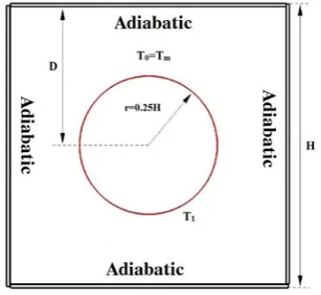
As shown in Figure 2, a circular-rectangular cross-sectional area is filled with paraffin wax and alumina nanoparticles, in which the center of the circle is located at the intersection of the rectangu-lar diameters. Circurectangu-lar-rectangurectangu-lar cross-section-al area is one of the common cross-sectioncross-section-al areas in engineering applications using the melting of a phase changing material, which is of interest to the present study. In this study, the initial temper-ature of the system is 298.15 degrees Kelvin. This operation is called “sub-cooling”. In this opera-tion, the phase changing material is cooled down prior to its melting temperature so that the melt-ing is not carried out instantaneously. The same can be seen in most of the previous work. In this research, the melting process of the internal wall is slowly applied. The purpose of this study was to study the different temperature contours, liquid fraction and to study the energy fraction diagrams to study the effect of nanoparticle fraction on the melting process and the melting mechanisms in its various stages. The research of the problem is phase changing from solid to liquid.
to investigate the effect of nanoparticle concen-trations on the melting rate of a phase chang-ing material enriched with nanoparticle, inside a cavity. For this purpose, different concentra-tions of nanoparticles are placed inside the en-closure, and from among different states, the best conditions are chosen of thermal performance of the compartment.
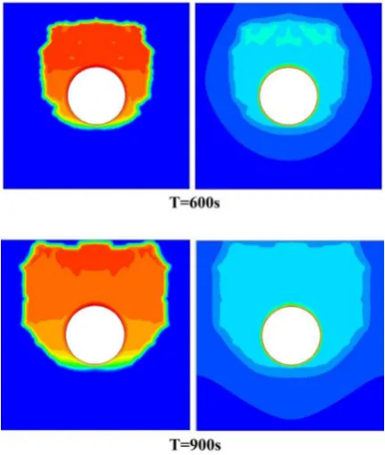
In this study, the heat transfers of heat con-duction in a not melted area with natural heat transfer of displacement is considered. Figs. 3 to 7 shows the temperature contours and liquid frac-tions for our problem. These formulas show the results for a paraffin wax phase changing mate-rial with a 1% volume fraction. Color contours on the right and liquid fraction contours appear on the left. In all liquid fraction contours, the blue section shows the not melted portion of the phase changing material. By analyzing the following figures, we start the analysis. The times that we have chosen to represent the contours are 30, 90,
240, 390, 600, 900, 1110, 1470, 1770 and 2220 seconds; the reason for these choices is the suit-ability of the melting pattern to justify the domi-nant melting processes in each stage.
At the beginning of the melting process, which is the dominant mechanism of heat con-duction transfer, and follows the Fourier rule, Gradual melting regularly and the temperature contour in the form of circles with same center occurs around the circular tube. In this phase, natural displacement does not play any role in the melting process, but this process does not last long, in our problem, up to 60 seconds, the dominant process is conduction. Gradually it by passing from the melting time, the melting pro-cess is slowly changing from conduction, this change can be seen with the observation of the temperature cluttered contours that have been re-moved from the circular state and have become irregularly shaped, This illustrates the change in the melting process from conduction to natu-ral displacement, which lasts from 90 seconds to 2000 seconds. If we look at the contour from 90 seconds later, we will notice that the melting process progresses to the top of the enclosure, the reason for this is natural displacement, because the density of melting material decreases. By de-creasing the density and lightening of the phase changing material, it moves slightly toward the top of the enclosure. As the contours show, after a certain period, the entire upper part of the tube in the liquid fraction contour becomes red, that is, all the phase changing material that is above the tube is melted. When all the phase changing material melts on the top of the tube, the heat transfer rate in this area is greatly reduced, because the heat Figure 1. Validation of the problem
with the research of Kumar [24]
transfers due to the difference in temperature be-tween the inner wall and the phase changing ma-terial while melted is greatly reduced, in this case, the melting process continues at the bottom of the tube, the difference between the melting process at the top and bottom of the tube in its dominant mechanism. The heat transfer mechanism is com-pletely different at the bottom and the top of the tube, when the phase changing material melts down the tube, the dominant mechanism of heat transfer is conduction, this can be verified by ex-amining temperature contours from 2000 seconds to the end of the melting process, at this stage, the melting continues as a completely horizontal line until it reaches the lower side of the rectangle until all the phase changing material is melted.
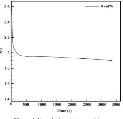
Diagram commonly considered in the process of melting phase changing material is the Nusselt chart of the circular wall in time. Figure 6 shows this graph for a zero percent volume fraction. At the beginning of the melting process, which is the dominant mechanism of heat transfer is conduc-tion, due to melting area with thin layer, a small thermal resistance has been created, so the Nus-selt number is at its highest, Over time, when the thickness of the layer increases, then the thermal resistance increases, so the Nusselt number de-creases over time, During the reduction of the Nusselt number, two mechanisms of heat transfer
and natural displacement are interacting, until the Nusselt number reaches a minimum point, Af-ter this point, the dominant mechanism is com-pletely natural displacement, this point is con-stant at least until the end of the melting process and does not change.
Figure 3. Temperature contours (right) and
liq-uid fraction (left) for 30 and 90 seconds Figure 4uid fraction (left) for 240 and 390 seconds. Temperature contours (right) and
CONCLUSIONS
In this study, melting of a phase changing material enriched with nanoparticles in a circu-lar ring-rectangucircu-lar enclosure was investigated and the results were analyzed. At the beginning of the melting process in the absence of a natu-ral displacement, the mechanism of conduction heat transfer around the hot cylinder is the domi-nant mechanism. Over time, natural displacement gradually appears and deforms the melting bound-ary above the cylinder. Over time, when the thick-ness of the liquid phase grows, the thermal resis-tance increases, this can be verified by reviewing the Nusselt chart. So this phenomenon reduces the rate of melting and temperature changes. The results show that increasing the nanoparticle vol-ume fraction due to increased conductivity and decreasing latent heat causes an increase in the melting rate and the amount of energy absorbed. From the study of various volume fractions, it can be concluded that the use of a higher volume frac-tion of 3% is more appropriate both in terms of energy and in terms of the melting rate. However, it should be taken into account that if the melting rate exceeds this value, it may cause agglomera-tion and deposiagglomera-tion of nanoparticles and reducing system efficiency.
REFERENCES
1. Dincer, I., & Rosen, MA. (2002). Thermal energy storage: systems and applications. Chichester,
2. Demirbas, MF. (2006). Thermal energy storage and phase change materials: an overview. Energy Sources Part B ,1, 85–95.
3. Mondal, S. (2008). Phase change materials for smart textiles – an overview. Appl Therm Eng, 28:15, 36–50.
4. Groulx, Dominic. “Numerical study of nano-en-hanced PCMs: are they worth it.” Proceedings of the 1st Thermal and Fluid Engineering Summer Conference, TFESC, New York City, USA. 2015. 5. Gao, Dongyan, et al. “Lattice Boltzmann
model-ing of meltmodel-ing of phase change materials in porous
media with conducting fins.” Applied Thermal En
-gineering 118 (2017): 315–327.
6. Jung, Uk-Hee, et al. “Numerical investigation on
the melting of circular finned PCM system using
CFD & full factorial design.” Journal of Mechani-cal Science & Technology 30.6 (2016).
7. Brent, A.D., Voller, V.R., & Reid, K.J. (1988). En-thalpy–porosity technique for modeling
convec-tion–diffusion phase change: application to the
melting of a pure metal, Numer. Heat Transfer, 13 (3), 297–318.
8. Beckermann, C., & Viskanta R. (1989). Effect of
solid subcooling on natural convection melting of a pure metal, ASME J. Heat Transfer 111, 416–424. 9. Asako, Y., Faghri, M., Charmchi, M., & Bahrami,
P.A. (1995). Numerical solution for melting of
unfixed rectangular phase-change material under
low-gravity environment, Numer. Heat Transfer, Part A 25, 191–208.
10. Wang, Y., Amiri, A., & Vafai, K. (1999). An ex-perimental investigation of the melting process in a rectangular enclosure, Int. J. Heat Mass Transfer 42, 3659–3672.
11. Gong, Z.X., Devahastin, S., & Mujumdar, A.S. (1999). Enhanced heat transfer in free convection-dominated melting in a rectangular cavity with an isothermal vertical wall, Appl. Therm. Eng. 19, 1237–1251.
12. Zhang, Y., Chen, Z., Wang, Q., & Wu Q. (1993). Melting in an enclosure with discrete heating at a constant rate. Exp. Fluid Therm. Sci. 6, 196–201. 13. Jianhua, Z., Zhongqi, C., Dengying, L., & Ji, L.
(2000). Experimental study on melting in a rect-angular enclosure heated below with discrete heat sources. J. Therm. Sci, 10 (3), 254–259.
14. Pal, D., & Joshi Y.K. (2001). Melting in a side heat-ed tall enclosure by a uniformly dissipating heat source. Int. J. Heat Mass Transfer 44, 375–387. 15. Hamdan, M.A., & Al-Hinti, I. (2004). Analysis of
heat transfer during the melting of a phase-change material. Appl. Therm. Eng., 24, 1935–1944.
of melting in an enclosure with discrete protruding heat sources. Appl. Math. Model, 34, 1258–1275. 17. Qarnia, H., Draoui, A., & Lakhal, E.K. (2013).
Computation of melting with natural convection inside a rectangular enclosure heated by discrete protruding heat sources. Appl. Math. Model, 37, 3968–3981.
18. Samara, F., Groulx, D., & Biwole, P.H. (2012). Natural convection driven melting of phase change material: comparison of two methods, in: Excerpt from the Proceeding of the COMSOL Conference. Boston, USA.
19. Voller, V. R., & Swaminathan, C. R. (1991).
Generalized Source-Based Method for Solidifi
-cation Phase Change. Numer. Heat Transfer B, 19(2),175–189.
20. Voller V. R., & Prakash, C. (1987). A Fixed-Grid Numerical Modeling Methodology for
Convec-tion-Diffusion Mushy Region Phase-Change Prob
-lems. Int. J. Heat Mass Transfer, 30, 1709–1720. 21. Kandasamy, R., Wang, X.Q, & Mujumdar, A.S.
(2008). Transient cooling of electronics using phase change material (PCM)-based heat sinks. Applied Thermal Engineering 28, 1047–1057. 22. Chow, L.C., & Zhong J.K. (1996). Thermal
con-ductivity enhancement for phase change storage media. International Communications in Heat an-dMass Transfer 23, 91–100.
23. Vajjha, R.S., Das, D.K., & Namburu, P.K. (2010).
Numerical study of fluid dynamic and heat trans
-fer performance of Al2O3 and CuO nanofluids in the flat tubes of a radiator. International Journal of
Heat Fluid Flow, 31, 613–621.
24. Kumar, Lokendra, et al. “Experimental investiga-tions on melting of lead in a cuboid with constant
heat flux boundary condition using thermal neutron