Research Journal
Volume 8, No. 21, March 2014, pp. 24–30
DOI: 10.12913/22998624.1091874 Original Article
Received: 2013.11.22 Accepted: 2014.02.04 Published: 2014.03.05
SIMULATION STUDY OF LONGITUDINAL FORCES IN THE COUPLING
DEVICE OF HEAVY FREIGHT TRAINS
Józef Stokłosa1, Marek Jaśkiewicz2
1 Faculty of Transport and Computer Science, University of Economics and Innovations, Projektowa 4, 20-209 Lublin, Poland, e-mail: [email protected]
2 Faculty of Mechatronics and Machine Building, Kielce University of Technology, 1000-lecia Państwa Polskiego 7, 25-314 Kielce, Poland, e-mail: [email protected]
ABSTRACT
On the LHS line (Broad-gauge Metallurgical Line), far out West of the railway line with a gauge of 1520 mm, heavy goods trains for a gross weight 5500 tons and a length of 850 m are operated. The article presents the results of a simulation study of the forces that occur in the automatic coupling device of SA-3 type of Russian produc-tion train consisting of 60 coal wagons of Russian construcproduc-tion of gross mass 91 tons each. The train moves on the 1520 mm gauge tracks curve S type (the radius of curva-ture of curves 300 m). Simulation studies were conducted using the Train Module of program to dynamic study multi-elements systems of Universal Mechanism UM 6.0. Keywords: heavy freight trains, the longitudinal forces in the coupling device, Nadal criterion, modeling, simulation, the theory of Kalker’s contact.
INTRODUCTION
The introduction of freight train operations with increased gross weight and increased length is one of the ways to improve railways capacity , especially one-track railways. Permissible length of freight trains shall not exceed the length of the usable main track and at least one master track additional on railway stations. In practice, the length of freight trains in Poland does not exceed 600 m, a weight of 3200 tons gross and depends
on factors such as a profile of the railway line,
power traction vehicle (or total power of all trac-tion vehicles), the length of statrac-tion track on inter-mediate stations [11,14].
On separated railways, both in Europe and on other continents, freight trains of mass gross much excess of 3200 tones are exploited. In Rus-sia and China the weight of heavy freight trains reaches 9000 and even 12 000 tones. In the USA, Canada trains weighing 15 000 gross tons operate. In Europe heavy freight trains with a gross weight exceeding 3200 tons are exploited among others
on Betuwe line of a length of 160 km, which leads from the port of Rotterdam to the German border.
The line is double track and electrified at 25 kV.
Maximum gross weight for trains on the Betuwe line is 5000 tons.
From the moment of the entry into opera-tion of the upgraded by Newag diesel locomo-tives of 311Da (modernized locomotive ST44) the company PKP LHS tried to conduct on the broad-gauge railway line no 65 (Polish/Ukrainian
border – South Sławków station) heavy trains of
mass gross 5500 tons and a length of 850 m. Train of the mass is drawn by two diesel locomotives 311Da.
SIMULATION MODEL
The experience of the countries in which heavy trains operate show that transitional pro-cesses have particular importance in the process of operation of such trains: acceleration and
-cantly increased thrust forces in coupling devices. Their amplitude is increased to a value that may result in rupture of the coupling [1, 4, 10, 12].
In the volume of cargo carried out by LHS line the largest share has iron ore which is imported from Ukraine to Dąbrowa Górnicza (Steelworks Katowice). LHS line is non-electrified monorail broad-gauge line (1520 mm), which allows the transport of cargo from Ukraine without reload-ing of the goods at the border from broad-gauge cars to normal cars.
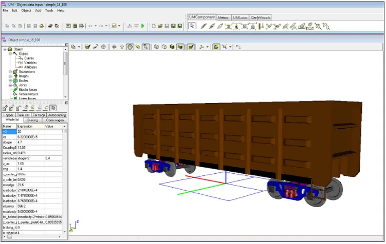
Ore Transport takes place in coal wagons of Russian construction (Figure 1) equipped with double-axle bogies type 18-100. Mass of unload-ed wagons is 22 000 kg, capacity 69 000 kg [3].
Simulation studies were conducted using the Train and Train3D modules as part of a program to simulate multi-elements systems called Uni-versal Mechanism v. 6.0 [13].
Universal Mechanism is the program oriented to practical engineers, students and teachers, in other words it is oriented to all people who are in-volved in problems of dynamics of machines and mechanisms. Mechanical systems are described by means of representing them as systems of rig-id bodies connected by various kinematical pairs and force elements, so-called multibody systems.
UM has advanced postprocessor, which in-cludes: linear analysis, statistics, multivariant cal-culation and optimization and export of results. UM is a useful tool for the computer-aided mod-eling of multibody and hybrid systems of various
types: complex aerospace structures, robots, rail-way vehicles, automobiles, cable systems, etc. It gives an opportunity to solve both direct and in-verse kinematic, dynamic, and control problems.
The program package includes module UM Loco, which is intended for simulation of dynam-ics of railway vehicles of different types (diesel and electric locomotives, passenger and freight wagons) in both straight and curve railroad tracks. The simulation is performed in time domain by means of numeric integration of differential or differential-algebraic equations of motion. UM Loco allows the user to create fully parameter-ized models of vehicles.
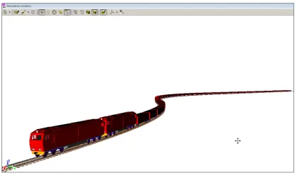
Model of train created with 60 coal wagons of gross weight 91 tones each was tested (Figure 2).
Wagons are connected by automatic couplers type SA-3 embedded in dampers Sh-2-T type of non-continuous draw gear (Figure 3).
This is a common construction used in freight wagons used by the railways of the Russian, Ukrainian, Belarusian, Kazakhstan. Automatic coupler SA-3 takes on longitudinal forces ex-tending during the drive of train, and compressive forces occurring during braking.
The schema of coupling device with damper was modeled as part of the elastic-frictional ele-ment placed in rigid frame-stepping of wagon ac-cording to schema: (spring + frictional element) + spring (Figure 4).
The research was conducted for the rail ve-hicle-track with the rails type R65 presenting a
basic type of rails on the LHS line (the standard type of rails on busy rail lines in Russia, and in the former Soviet republics) and the wheels of PU1Sz-950 profile and the diameter of the new wheel 950mm.
The composition is driven by two diesel loco-motives type 311Da (PKP ST40) operated from the driver’s cab of the first locomotive. The loco -motive ST40 is a heavy traction vehicle based on two three-axle trucks in a Co - Co system, devel-ops the power of 2133 kW (2900 KM) with total weight of 126,9 tons [6]. The driving force, fol-lowed by six traction motors type ED 118A GE, was asked in the form of the traction characteris-tics of the locomotive (Figure 5).
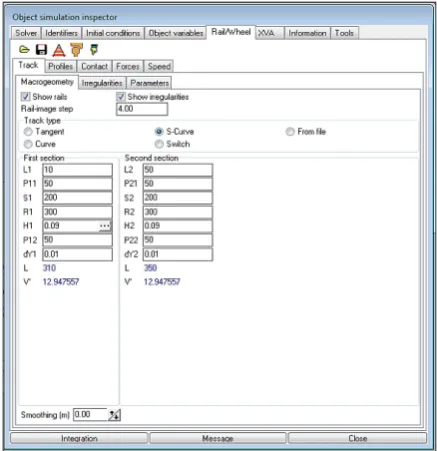
The train was moving on the track curve S. On the Figure 6 described the components of a
geometric system of the track and line profile is shown in Figure 7.
In addition, it is assumed that on the straight sections rails have not used profile, while in the curves and spirals external rail course has worn profile unilaterally on the inner side of the ongo -ing rail friction wheel flanges on roll-ing stock (Figure 8).
The model includes a basic resistance and re-sistance to motion in the curvature of the track. Due to the fact that in the test train composed of Russian construction wagons and moves along a wide track (1520 mm) to describe the resistance forces train traffic is based on fundamental pat -terns used on Russian railways [9].
The essential resistance to movement of die-sel locomotives and electric [9]:
Fig. 2. Model of freight train made in UM program.
Fig. 3. Automatic coupler SA-3 along with frictional damper Sh-2-T [13]
Fig. 5. Sample traction characteristics of electric locomotive
Fig. 6. Macro-geometry of railway line: L0, L – straight segment, P11, P12, P21, P22 – temporary curves, S1 – an arc of radius R1, H1 – superelevation
of track, dy – widening of the track in the arc Fig 7. Profile line specified in UM program
RESULTS OF SIMULATION STUDIES
The train was moving at a speed of v = 10 m/ sec. At the start of simulation the face on the first locomotive was at the beginning of the straight section of the track (the beginning of the line L0 in Figure 6). Simulation time has been chosen in such a way that the whole composition has trav-elled by the curved section of the track.
Braking process begins in the 5th second of
simulation. The train moves in braking mode. Let us assume that the speed of propagation of air in the brake line (the so-called wave speed braking) is 250 m/s. As a result the start or end of the brak-ing process is not simultaneous in all wagons.
Figure 10 shows a graph of longitudinal forces in the coupling in the middle wagon. significant compression force jumping to a value of 500 kN are visible.
In the last wagon of train there are also mo-mentary compressive forces of considerable val-ues up to 500 kN (Figure 11). As a result, the op-eration of such large compressive forces can lead to derailment of wagons.
(1)
The essential movement resistance four-axles wagons [9]:
(2)
where:
WoL – the essential resistance to movement of the locomotives in [N], QL – the mass of the locomotive in [t],
QW – the weight of load wagon in [t], v – the speed of train in [m/s].
The additional traffic resistance – resistance to motion in the curvature of the track [9]:
(3) where:
WŁ – resistance to motion in [N], R – the radius of the arc in [m],
Sk – the length of the curvature of the track in [m], L – the length of train in [m],
a – the empirical factor
The relationship of forces in the wheel/rail contact from micro-skids is evaluated by us-ing a simplified non-linear contact Kalker’s theory [5].
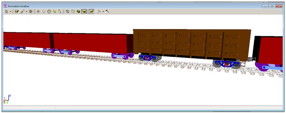
The UM Program allows to insert to a simpli-fied model of train wagon made in 3D technolo-gy anywhere in the train set (Figure 9). Inserting 3D wagon allow sets of forces that occur in the wheel/rail contact point and the designation of the value of the coefficient of Y/Q – criteria for safety against derailment based on designation of the transverse forces Y to the vertical Q at the point of wheel/rail contact.
Fig. 9. View of portion of the model train with inserted wagon model 3D to determine the forces
Fig. 10. The longitudinal force in compression coupling SA-3 in wagon No 33 (middle wagon)
CONCLUSIONS
The article gives the part carried out by the authors, research the dynamics of heavy freight train. In further research, according to the au-thors, should be taken into account the exact pa-rameters of the LHS line - the status of the track, the degree of wear of the rails, the inclination of the line. In addition, research should be subject to the status of the braking system. The authors are aware that the company PKP LHS is not the own-er of the moving wagons on the track wide from Hrubieszów to Slavkov, however, research on the dynamics of long trains serve to get to know the process of braking such heavy formations.
Fig. 11. A longitudinal forces in the coupling in the last wagon
REFERENCES
1. Delooz F. Heavy haul trains in Europe. 9th
Internatio-nal Heavy Haul Conference IHHA, Shanghai 2009.
2. EN 14363: Railway applications – Testing for the
acceptance of running characteristics of railway
vehicles. Testing of running behavior and station
-ary tests. European Committee For Standardiza
-tion, 2005.
3. Gruzowyje wagony kolei 1520 mm. Albom spra
-wochnik. Wydawnictwo Transport, Moskwa 1989. 4. Hongyan Zh. Dynamic Interact Heavy Haul Rail
-ways on Track Structures. Chinese Rail-ways, No. 1, 2005: 38-42.
5. Kalker J.J., Piotrowski J. Some New Results in Roll
6. Marciniak Z., Durzyński Z. Projekt modernizacji lokomotyw spalinowych serii ST44. TTS 9, 2005. 7. Pogorelov D.Yu. Computer Modeling of Rail
Vehi-cles Dynamics. Mechanics and Tribology of Trans-port Systems, Rostov-on-Don 2003: 226-231.
8. Pokropiński B. Lokomotywy spalinowe produkcji
polskiej. WKiŁ, Warszawa 2009.
9. Pravila tiagovyh raschiotov iz pojezdnoy raboty. M. Transport. 1995.
10. Pugi L, Fioravanti D, Rindi A. Modelling the lon-gitudinal dynamics of long freight trains during the
braking phase. 12th IFToMM World Congress, Be
-sançon (France) 2007.
11. Rozporządzenie Ministra Infrastruktury z dnia 18.07. 2005 r. w sprawie ogólnych warunków prowadzenia ru-chu kolejowego i sygnalizacji, Dz. U. Nr 172, poz. 1444. 12. Schmidt S. et al. ZEVrail, 9, 2009: 358-364. 13. Universal Mechanism 6.0, Simulation of
Longitu-dinal Train Dynamics. User’s manual, 2010.
14. Założenia techniczno-eksploatacyjne kierowania i stero-
wania ruchem (KSR) dla PKP, uzgodnione z PKP DG