Available Online At www.ijpret.com
INTERNATIONAL JOURNAL OF PURE AND
APPLIED RESEARCH IN ENGINEERING AND
TECHNOLOGY
A PATH FOR HORIZING YOUR INNOVATIVE WORK
EFFECT OF SHORT CARBON FIBRES ON FLEXURAL TENSILE STRENGTH OF
CONCRETE
HAFIZ ASFANDYAR AHMED1, KHAN SHAHZADA2, MOHAMMAD JAVED2, BASHIR ALAM2
1. Graduate student, Department of Civil Engineering, University of Engineering & Technology Peshawar, Peshawar 25120, Pakistan.
2. Faculty member, Department of Civil Engineering, University of Engineering & Technology
Peshawar, Peshawar 25120, Pakistan
Accepted Date:
18/10/2012
Publish Date:
01/11/2012
Keywords
Tensile strength
Carbon fibress
Modulus of rupture
Plain concrete
Corresponding Author
Mr. Mohammad Javed
Faculty member, Department of Civil Engineering, University of Engineering & Technology, Pakistan.
Abstract
Use of short carbon fibers in concrete improves some important properties (i.e. flexural tensile Strength, toughness etc.). The flexural tensile strength of concrete is specially very important property as it indicates the
limitation on the use of concrete in structural
Available Online At www.ijpret.com
INTRODUCTION
Flexural tensile strength of plain concrete, fr,
commonly known as modulus of rupture
(MOR) is an important property of concrete
and is used in the design of short span slabs,
road pavements, etc. In this investigation,
results of experimental work to study the
effect of short carbon fibers (type of fibers
with 98% carbon content and are available
in length of 5±1 mm) on fr is discussed.
Beams, moist cured for at least 28 days,
were subjected to MOR test. These beams
were fabricated using four types of mixes
designated as CC, Type A, Type B and Type C
on the basis of amount of short carbon
fibers. Type CC mix had no carbon fibers,
while types A, B and C contained carbon
fibers with amount of 0.35%, 0.5%, and
0.65%, respectively, by weight of cement.
RESEARCH SIGNIFICANCE
Concrete is a material which performs well
under compression and is best to use in
situation where compressive strength is of
prime importance. It also exhibits limited
tensile strength. MOR tests are performed
to measure flexural strength of plain
concrete. If the flexural tensile cracks,
during the test, are produced within the
middle third portion of the beam’s clear
span then the modulus of rupture, fr , is
determined by the Equation 1 as follows:
fr = Pl/bd2 …………. 1
Equation 1 is derived using equilibrium
conditions for simply supported beam
loaded at third point. Where
fr = Modulus of rupture ; P = Maximum
vertical load applied by the testing machine;
l = Length of the specimen between
supports; b = width of the beam; and d =
depth of the beam
However, if the cracks are produced outside
the middle third of the clear span of beam
by not more than 5% of the clear span
length, then the modulus of rupture is
determined by the following equation.
fr = 3Pa/bd2 ………. 2
Where ‘a’ is the average distance between
line of fracture to the nearest support
measured on tension side of the beam.
The test results of a sample is discarded if
Available Online At www.ijpret.com
the middle third of clear span by more than
5%,
MIX PROPORTION
Mix proportions for Normal Concrete were
made with a compressive strength of 28
MPa by using ACI 211.11. Results of mix
proportions are as follows in Table I:
Other materials that were used in the
concrete included Carbon fibers, Silica
Fume (8% by weight of cement),
Methylcellulose (0.4% by weight of cement)
and Plasticizers (1.5% by weight of cement).
Methylcellulose was used for dispersing the
fibres in the concrete. While silica fume was
used to increase the bond strength of
concrete with carbon fibers. Whereas,
Plasticizers were used to impart proper
workability as using the silica fume results
in a harsh concrete mix.
Four different types of concrete mixes were
used in the experimental work on the basis
of varying amount of short carbon fibers.
These mixes were designated as Controlled
Concrete (CC); Type A, Type B, Type C
having Carbon fibres by amount of 0%,
0.35%, 0.5%, and 0.65% respectively by
weight of cement. The details of mix
proportions are given in the Table II.
Table-1 Mix proportion Values
S. No. Material Quantity
(kg/m3)
1. Cement 364
2. Fine Aggregate 831
3. Coarse
Aggregate
906
Available Online At www.ijpret.com
MIXING PROCEDURE
Mixing of concrete was carried out at
normal temperature. Care was taken that
during mixing process, all the steps should
be taken in accordance with ASTM C11162.
The concrete batches were made by a
concrete Mixer Machine using following
procedure:
Coarse aggregates were first placed in the
mixer machine and water was added in a
nominal amount to wet the coarse
aggregate. Mixer machine was allowed to
start rotating.
Then Silica Fume as per ASTM C12403 was
added an an amount equal to 8% by weight
of cement to the mixer machine containing
wet aggregates.
Fine aggregates were added to the rotating
mixer machine.
Methylcellulose was dissolved in the water
and the solution was shaked for 2 minutes.
Carbon fibres were then added to the
solution. This resulted in a thick black paste
as shown in Figure 1.
Figure 1 Carbon fibres in Methylcellulose
Table I Details of Mix proportions Mix
type
Carbo n fibers (%)
Fine agg. (kg/m3)
Coarse agg. (kg/m3)
Cement (kg/m3)
w/c Silica
Fume (%)
Plasticiz er (%)
Methyl cellulose (%)
CC 0 831 906 364 0.57 8 1.5 0.0
Type A 0.35 831 906 364 0.57 8 1.5 0.4
Type B 0.50 831 906 364 0.57 8 1.5 0.4
Available Online At www.ijpret.com
This paste of methylcellulose and carbon
fibres was also added to the mixer machine.
Finally, plasticizers were added to the mixer
machine and all the material was allowed to
mix for 3 minutes.
TEST PROCEDURE
Beam samples with 450 mm x 100 mm x 100
mm size were made in the lab to determine
the modulus of rupture as per ASTM C78
standards4. All the beam specimens were
cast and cured in accordance with ASTM
C192 specifications5. Beams specimens,
tested using universal testing machine
(UTM), were supported on both sides. 75
mm length of beam from each face of the
support was supported on thick steel plates
as shown in Figure 2. The remaining 300 mm
length was divided in three equal portions
to accomplish the ASTM C78 requirements
that the intermediate distance between
points should be equal to depth of the
beam. Circular rods, with an overlying thick
steel plate, were used to equally transfer
the point load applied through UTM as
shown in Figure 2.
Figure 2 Setup for MOR test
Figure 2 Beam at failure
Care was taken during the testing to
observe the cracks generation i.e. whether
the cracks were produced within the middle
third of the beam clear span or otherwise. It
was observed that tensile cracks were
produced within middle third portion of all
the tested beams (Figure 3) and, therefore,
Equation 1 was used to determine fr
RESULTS AND DISCUSSIONS
Results of the experimental work are given
Available Online At www.ijpret.com
4.5 5 5.5 6
0 0.35 0.5 0.65
Amount of Carbon fibers (% weight of cement)
F le x u ra l te n s il e s tr e n g th ( M P a )
Figures 3 and 4 taking controlled concrete
(Type CC) as reference.
It can be seen from Figure 4 that the flexure
tensile strength of concrete increases with
an increase in the amount of short carbon
fibers. A direct relation between percent
increase in flexural tensile strength and the
amount of carbon fibers6, 7, 8 can also be
seen from Figure 5.
This increase in strength can be attributed
to the increase in bond strength of fibers
with cement due to silica fume.
Figure 3 Variation in flexural tensile strength with amount of carbon fibers
Figure 4 Percent increase in tensile strength w. r. t controlled specimen
CONCLUSSION
On the base of tests results, it can be
concluded that use of short carbon fibers in
plain concrete increase the tensile strength
of concrete. This increase in strength may
be credited to the reinforcing action
developed by the bond between fibers and
concrete. The reinforcing action increases by
increasing the amount of fibers that causes
the flexural tensile strength to increase
further.
FUTURE WORK
Effect of further increase of carbon fibers
amount on the flexural tensile strength shall
be investigated. The existing and additional
0 3 6 9 12 15
0 0.2 0.4 0.6 0.8
Amount of Carbon fibers (% weight of cement)
In c re a s e i n f le x u ra l te n s il e s tr e n g th ( % )
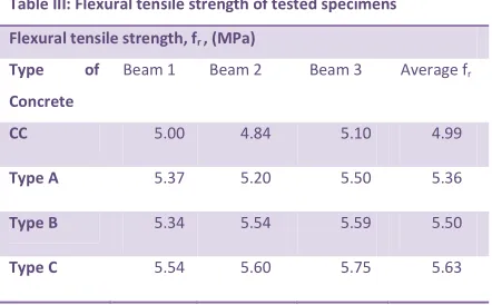
Table III: Flexural tensile strength of tested specimens
Flexural tensile strength, fr , (MPa)
Type of
Concrete
Beam 1 Beam 2 Beam 3 Average fr
CC 5.00 4.84 5.10 4.99
Type A 5.37 5.20 5.50 5.36
Type B 5.34 5.54 5.59 5.50
Available Online At www.ijpret.com
data may be used to develop empirical
relation between amount of carbon fibers
and flexural tensile strength. Similarly
influence of various fibers length on the
flexural tensile strength of concrete having
same amount of carbon fibers shall also be
studied.
ACKNOWLEDGMENT
I am thankful to the department of Civil
Engineering, University of Engineering &
Technology Peshawar for providing the
necessary assistance in conducting these
tests. I am also grateful to Dr. Deborah L.
Chung (Department of Mechanical and
Aerospace Engineering, State University of
New York at Buffalo) for providing me the
proper guidance. I am also thankful to Prof.
Dr. Jahangir Mirza, (Hydro Quebec,
Montreal, Quebec, Canada) for his amazing
help.
REFERENCES
1. ACI 211.1. Standard Practice for selecting
Proportions for Normal, Heavy weight and
Mass Concrete.
2. ASTM C1116, Standard Specification for
Fibre-Reinforced concrete and Shotcrete.
3. ASTM C1240, Standard Specification for
use of Silica Fumeas a Mineral admixture in
Hydraulic Cement Concrete, Mortar and
Grout.
4. ASTM C78, Standard Test Method for
Flexural Strength of Concrete.
5. ASTM C192, Standard Test Method for
Making and Curing Concrete Test Specimen
in the laboratory.
6. Dr. Deborah D.L. Chung, Carbon Fibre
Reinforced Concrete, SHRP-ID/UFR-92-605.
7. S. Furukawa, Y. Tsuji and S. Otani, Proc.
Jpn. Congr. Mater. Res., 1987; 30: 149- 152.
8. S. Akihama, T. Suenaga and T. Banno,
Int. J. of Cement Composites & Lightweight