Available Online at www.ijpret.com 410
INTERNATIONAL JOURNAL OF PURE AND
APPLIED RESEARCH IN ENGINEERING AND
TECHNOLOGY
A PATH FOR HORIZING YOUR INNOVATIVE WORK
CONTROLLING TECHNIQUES OF SHUNT ACTIVE POWER FILTER FOR POWER
QUALITY IMPROVEMENT
NISHIGANDHA V. JUMALE1, PROF. Y. H. KHAIR (SHAHAKAR)2 1. Student, Electrical Engineering, P. R. Pote (Patil) College of Engg. & Management Amt, India. 2. Asst. Professor, Electrical Engineering, P. R. Pote (Patil) College of Engg. & Management Amt, India
Accepted Date: 05/03/2015; Published Date: 01/05/2015
\
Abstract: The recent decades the world has seen an expansion in the used of power electronics equipment in modern electrical systems such as switch mode power supplies; non-linear characteristics load etc. but using such loads draw a non-sinusoidal current from the source and distribute them throughout the system. Therefore the recent effort developed for solving such problems active power filter is used. Basically there are two types of active power filter: series type and shunt type. This paper deal with the mitigation of harmonic problem and also for reactive power compensation using control of shunt active power filter (SAPF) from two different aspects Synchronous Detection Method (SDM) and digital control based on instantaneous power theory (p-q theory). The application of these two methods to the control of SAPF using MATLAB SIMULINK and simulation results are demonstrated. Moreover this paper also proves the digital control method improves power quality better than the SDM.
Keywords: Power Quality, Shunt Active Power filter, Synchronous Detection Method, digital control, p-q theory.
Corresponding Author: MS. NISHIGANDHA V. JUMALE
Access Online On:
www.ijpret.com
How to Cite This Article:
Available Online at www.ijpret.com 411 INTRODUCTION
In Modern electrical systems the tendency of connecting nonlinear load in industry as well as in domestic such as power converters, adjustable speed drives, fast switching devices etc. are increasing day by day. But using such power electronics devices and Loads are the sources of harmonics & reactive power which greatly affect the performance of the power system network [1].
These present of harmonic results the problems in power system such as power losses in distribution system, failure of protection devices, electromagnetic interference in communication system, over heat etc. and also quality of power supply to the end consumers is not suitable format. For reducing the harmonic distortion problem last decades uses a passive filter but passive filter have been many disadvantages as it only filters the frequency has previously tuned for, for the certain load operation cannot be limited, resonance occurs at interaction between passive filter and their load and gives unpredictable result [1]. Because of such disadvantage the recent development is active power filter. Active power filter have gained much more attention because of excellent performance to mitigate the harmonic and reactive power issues [1].
In this paper detail discussion about the main working principle of shunt active power filter in section II. Here the mathematical analysis of controlling methods of SAPF explains in section III. The simulation model developed for both controlling methods are explain in section IV and gets the simulation results which are shown in section V [1]. Here also comparing the simulation results of two methods and this comparison shows that power quality improvement using p-q theory gives better result than SDM.
II.OPERATING PRINCIPLE OF SAPF
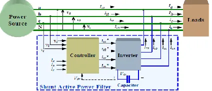
Available Online at www.ijpret.com 412 Figure 1: Operation of Three Phase Shunt Active
Power Filter
Basically the shunt active filter containing two blocks which is shown in figure 1 above. First block is a control block i.e. controller it generates a reference current as ica*, icb* , icc*, icn* from the measured value of phase voltages va, vb and vc and non linear load currents ia, ib and ic as shown in figure. Second block is a IGBT based voltage source inverter which is a bilateral converter and it is controlled in the current regulated mode. A dc capacitor is usually work as a source of power in voltage source inverter. This voltage source inverter calculates the compensating currents as ica, icb ,icc,icn from reference current. In this paper discuss the two methods of controlling the SAPF as SDM and p-q theory [2].
III.MATHEMATICAL ANALYSIS OF CONTROL METHODS
In this section discuss the mathematical analysis of two controlling methods of shunt active power filter as SDM and P-Q theory [2].
3.1Mathematical analysis using synchronous detection method
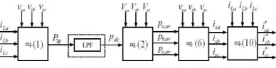
This method works under both balanced and unbalanced condition because the compensating current is calculating using per phase voltage magnitude of the line also it is assumed that after compensation the three phase main current is balanced and also it tries to determine the required amplitude of main current [3]. In this method firstly calculating the instantaneous power using instantaneous values of supply voltage as va(t), vb(t) and vc(t) and non linear load current as ia(t), ib(t) and ic(t) measured from line [3]. After calculating this real average power it is divided equally among the three phases. The real power p(t) is calculated from equation below,
Available Online at www.ijpret.com 413 Figure 2: block diagram of the synchronous detection calculation
After calculating the real power p(t) then calculate the average power pdc . This average power pdc is calculating by applying the real power p(t) to the low pass filter as seen in figure 3 above [4]. After calculating power this real power is split into three phases,
Pa=(Pdcvam)/(vam+vbm+ vcm) (2)
Pb=(Pdcvbm)/(vam+vbm+ vcm) (3)
Pc=(Pdcvcm)/(vam+vbm+ vcm) (4)
Where, vam, vbm and vcm are the amplitude of the instantaneous value of supply voltages va(t), vb(t) and vc(t) resp. By using this power the balanced per phase line current is determined as,
isa = (2vaPa)/v2am (5)
isb = (2vbPb)/v2bm (6)
isc = (2vcPc)/v2cm (7)
After calculating the balanced per phase line current compensation reference current is determine by subtracting the non linear load current ia,ib and ic from positive sequence current isa,isb and isc as follows,
I*ca = isa - ia (8)
I*cb = isb - ib (9)
I*cc = isb - ic (10)
The compensation per phase reference currents i*ca, i*cb and i*cc is given to the voltage source inverter it gives exact replica of these current i.e. ica, icb and icc. The voltage source inverter gives the compensating current which is of equal in magnitude of line current and phase opposition of harmonic current [3].
Available Online at www.ijpret.com 414
In 1983, Akagi et al. have proposed the generalize theory based on instantaneous reactive power theory also known as p-q theory [4]. The p-q theory consists of an Clarke transformation in which the three phase voltages and currents in a-b-c coordinate transform into α-β-0 coordinate for calculation of instantaneous value of active and reactive power as follows,
[vα vβ v0] = A*[va vb vc]’ (11)
[ i0 iα iβ ] = A* [ ia ib ic ]’ (12)
Where, A= √2 3
[ 1 √2
1 √2
1 √2 1 −1
2 −1
2
0 √3 2
−√3
2 ]
is a Clarke transformation matrix and
p0= v0 i0 (13)
p= vα iα + vβ iβ (14)
q= vα iβ - vβ iα (15)
This power component p and q are related to the α-β of the voltage and current which is written in matrix form as,
(16)
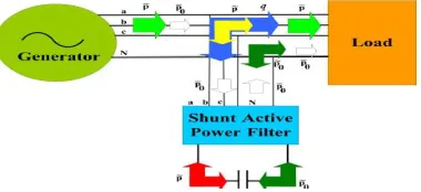
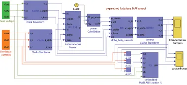
The figure below shows the p-q theory applied to the SAPF and also shows the desirable power components in p-q theory.
Available Online at www.ijpret.com 415
In p-q theory only p is a desirable quantity because it corresponds to energy transferred from power supply to the load. All other power components obtain from the p-q theory is less desirable and it is compensated by SAPF. The Watanabe et al. [4] proposed a convenient way to compensate the p0 without the any need of power supply to the SAPF. Using this theory all the power components are compensated and deliver from source to the load through the SAPF [4].
The figure above shows that the dc capacitor is connected to the active power filter to compensated P͠0 and P͠ alternating power component of p-q theory. The remaining power component is instantaneous reactive power compensated without the use of dc capacitor. This means that the size of dc capacitor is not depends up on the reactive power to be compensated. Because of this the size of capacitor is reduce and also cost is less.
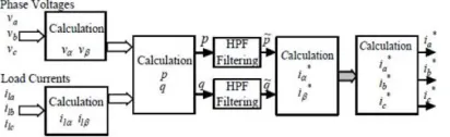
Figure 4: Control diagram for SHAF using p-q control theory
The figure above shows the control diagram for shunt active power filter using p-q theory. After calculating the power component using p-q theory the next important component is high pass filter for calculating the reference compensating current [6]. The high pass filter used with cut off frequency of 50Hz which takes the input as instantaneous real power from equation 13, 14, 15 & filters all the frequency of power greater than the fundamental power. The output waveforms of the high pass filter containing harmonic which is in current form [5]. To calculating compensation reference current icα* and icβ* using power component as follows,
[icα ∗
i𝑐𝛽∗ ] = 1 vα2+vβ2
[vv𝛼 −v𝛽
𝛽 v𝛼 ] [
pz
qz] (17)
Where, Pz and qz are the power component which is compensated.
Pz = P͠ - ∆P͞ (18)
∆P͞ = P͞0 (19)
Available Online at www.ijpret.com 416
The compensation reference current in zero sequence is equal to the zero sequence current i0 itself i.e. i*c0 = i0. After calculating the reference current, the compensation current is calculated by using the inverse Clarke transformation is applied as follows,
[ ica∗ icb∗ icc∗
] = √2 3
[ 1
√2 1 0
1 √2 −1 2 √3 2 1 √2 −1 2 −√3 2 ] [ i0∗ i𝛼∗ iβ∗
] (21)
icn = -(i*ca + i*cb + i*cc) (22)
After calculating the compensating reference current, it gives to the voltage source inverter. The voltage source inverter determine exact replica of this current which is of equal magnitude of line current and opposite magnitude of harmonic current [5].
IV.SIMULATION MODELS FOR CONTROL METHODS OF SAPF
In this paper used the matlab simulink tool for developed simulation model for both controlling methods as SDM & p-q theory. Here the main components are as overall three phase system of 230v 50Hz having maintained the voltage of 230v per phase supplying to the nonlinear load which is of resistive type and inductive type shown in figure and compensated by SAPF [6].The figure 5 & 6 below shows the simulation model developed for SDM and digital control method [6].
Figure 5. Simulation model developed for SDM calculation
Available Online at www.ijpret.com 417 V.SIMULATION RESULT
The balance three phase system is consider for the calculation having sinusoidal supply voltage presented as figure 7. Also consider various type of load are used for each phase which are for set A load as phase a: consider a typical single phase half wave rectifier with resistive load on dc side, for phase b: consider the linear RL load which gives the sinusoidal current wave forms but delayed by the phase voltage and for the phase c: consider the other non linear load as single phase full wave bridge rectifier with dc motor load is connected [6]. These per phase load current are shown in figure 8.
Figure 7. The three phase balanced line voltages (a)va,(b)vb and (a)vc
Figure 8. The three phase load currents for load set A (a)ia,(b)ib and (a)ic
According to this non linear load current both SDM and p-q theory generates the compensation current for set A load which is shown in figure 9 and 10 resp. [6].
Figure 9. Three phase compensation currents for load set A (SDM-SAPF) (a)ica, (b)icb and (c)icc
Available Online at www.ijpret.com 418
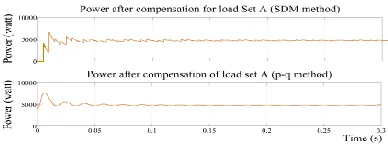
The SAPF also compensated the undesirable power component by turning the instantaneous supply power into the constant values [7]. The instantaneous power for load A shown in figure 11 below.
Figure 11. Overall source power after compensation for load set A
The table I shows the values of total harmonic distortion, power factor and displacement power factor before and applying the SAPF [7]. By application of SAPF the value of power factor is maintain to unity and percentage of total harmonic distortion reduce from some value to zero.
Table I. THD, PF and DPF after and before compensation
Condition Phase
Before Compensation After Compensation
a b c a b c
THD% 43.52 0.00 48.34 0.0 0.0 0.0
PF 0.3925 0.7036 0.9004 1.0 1.0 1.0
DPF 1.0 0.7036 1.0 1.0 1.0 1.0
After the calculation of compensation current using both the methods comparing the performance of two methods it shows that the digital control method gives a faster result than SDM. It means that p-q theory shows that compensate the undesirable current component from resultant supply current require 1 cycle whereas SDM compensated this current takes about 14 cycles i.e. approximately 0.23 sec is required for 50 Hz system [7]. This shows that p-q theory required less time than SDM to clear the harmonic current and for power quality improvement. So the digital control method is preferable than SDM.
VI.CONCLUSION
Available Online at www.ijpret.com 419
and power factor correction solution. This paper also calculated results using matlab simulation and proves that p-q theory implemented to control shunt active power filter that faster power quality improvement than the SDM. So that preferred the digital control method than SDM for power quality improvement.
REFERANCES
1. Chandra, A., B. Singh, B.N. Singh and K. A. Haddad, 2000. An Improved ControlAlgorithm of Shunt Active Filter for Voltage Regulation, Harmonic Elimination, Power-factor Correction, and Balancing of Nonlinear loads: IEEE Trans. Power Electronics, 15(3): 495-507.
2. A. Emadi, A. Nasiri, and S. B. Bekiarov, Uninterruptible power supplies and active filters: CRC, 2005.
3. S. Round, H. Laird, R. Duke, and C. Tuck, "An improved three-level shunt active filter." vol. 1: Power Electronic Drives and Energy Systems for Industrial Growth International Conference, 2004, pp. 87-92.
4. A. N. H. Akagi, Y. Kanazawa, “Generalized theory of the instantaneous reactive power in three-phase circuits,” IPEC’83 - Int. Power Electronics Conf., Tokyo, Japan, 1983
5. H. Lev-Ari and A. M. Stankovic, "Hilbert space techniques for modeling and compensation of reactive power in energy processing systems." vol. 50: IEEE Transactions on Circuits and System Part 1: Regular Papers, 2003, pp. 540-556.
6. Bhim Singh, Kamal Al-Haddad, Senior Member, IEEE, and Ambrish Chandra, Member, IEEE “A Review of Active Filters for Power Quality Improvement” ieee transactions on industrial electronics, vol. 46, no. 5, october 1999.