Available Online at www.ijpret.com 1184
INTERNATIONAL JOURNAL OF PURE AND
APPLIED RESEARCH IN ENGINEERING AND
TECHNOLOGY
A PATH FOR HORIZING YOUR INNOVATIVE WORK
PERFORMANCE EVALUATION OF GRID CONNECTED 5-LEVEL AND 7-LEVEL
INVERTERS
SAPNA B. VERMA1, M. J. KATIRA2, S. S. AMBEKAR3
1.Student M. Tech., Department of Electrical Engineering, G.H. Raisoni Institute of Engineering and Technology for Women, Nagpur. 2.H.O.D., Department of Electrical Engineering, G.H. Raisoni Institute of Engineering and Technology for Women, Nagpur.
3.H.O.D., Department of Electrical Engineering, K. D. K. College of Engineering, Nagpur.
Accepted Date: 05/03/2015; Published Date: 01/05/2015
\
Abstract: Inverter is basically a power electronic device used for DC to AC conversion. A multilevel inverter is an advanced form of inverter which is used for high voltage and high power applications. It gives high power quality improved waveform and reduced total harmonic distortion (THD) than the conventional inverters thus it reduces the bulkiness and size of passive filters. As the level of multilevel inverter increases we get more and more improved output waveform and reduced THD which is an advantage on the other hand the cost and complexity of circuit increases thus producing disadvantage of using higher levels. For this reason to make proper choice between various levels in this paper comparison is made between 5-Level and 7-Level inverter using a developed H-bridge circuit connected to grid. This circuits are simulated using Sinusoidal Pulse Width Modulation Technique (SPWM), one of the PWM technique used. The circuits are modelled and simulated using MATLAB/Simulink.
Keywords: 5 level inverter, 7 level multilevel inverter, H bridge Inverter, Diode clamped
Inverter, Cascaded multilevel inverter, Flying Capacitor.
Corresponding Author: MS. SAPNA B. VERMA
Access Online On:
www.ijpret.com
How to Cite This Article:
Available Online at www.ijpret.com 1185
INTRODUCTION
Inverters are in great demand in today’s world because of its usefulness in case of emergency. Lot of work is already done on it to get more and more developed form which would consume less power and give maximum output.. Multilevel inverter is an advanced form of inverter which gives stepped output thus reduces the voltage stress. As we increase the level of multilevel inverter it gives more and more improved output waveform i.e. the output waveform approaches towards nearly sinusoidal with the increase in level hence the total harmonic distortion also low, reduced switching losses and the filter needed to smooth the output voltage is small hence, the system is compact, lighter and much cheaper..
There are different types of multilevel circuits that are evolved with the time and demand. The first topology introduced was diode clamped converter, which utilized a bank of series capacitors. A later invention detailed the flying capacitor design in which the capacitors were floating rather than series-connected. Another multilevel design involves parallel connection of inverter phases through inter-phase reactors. In this design, the semiconductors block the entire dc voltage, but share the load current. The cascaded multilevel control method is very easy when compare to other multilevel inverter because it doesn’t require any clamping diode and flying capacitor thus superior than the conventional one.
In this paper PV Arrays is used in place of DC input. Solar panel refers to a photovoltaic module made up of semiconducting materials electrically connected and mounted on a supporting structure. A single solar module can produce only a limited amount of power therefore most installations contain multiple modules. A photovoltaic system typically includes a panel or an array of solar modules, an inverter, and sometimes a battery and/or solar tracker and interconnection wiring. The electrons knocked from the atom due to absorption of solar energy flows through the material and thus electricity is produced. Each module is rated by its DC output power under standard test conditions STC), and typically ranges from 100 to 320 watts.
The circuit which is introduced in this paper for comparison is developed H-bridge having less number of switching devices than the cascaded one but giving the same output and levels. Further it is shown that the 7-Level is superior than the 5- Level in terms of efficiency and reduced Total harmonic distortion but the cost and complexity increases thus the comparison of two multilevel inverters is necessary before its purchase
COMPARISON OF 5-LEVEL WITH 7-LEVEL INVERTER
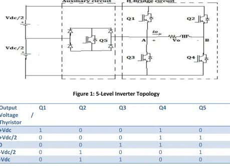
Available Online at www.ijpret.com 1186 The figure 1. shows the 5-level inverter topology which is basically like a conventional inverter with an extra auxiliary circuit which have switch Q5 and four diodes connected to it which is
responsible for producing extra two levels over the conventional inverter which normally gives 3-Levels for the same input thus 5-Level reduces the voltage stress as steps is increased in its case. If single DC input used than to make it two, capacitor can be used as voltage divider, as shown in figure but if separate DC input (Two) used as in figure 1. then there is no need to use capacitor. In this paper PV arrays is used in place of DC input. The 5Levels ie Vdc, +Vdc/2, 0, -Vdc & --Vdc/2 is created using the 5 switches and 4 diodes present in circuit. The operation of the circuit and the voltage levels is decided using particular combination of switches which is explained in table below :
Figure 1: 5-Level Inverter Topology
Output
Voltage /
Thyristor
Q1 Q2 Q3 Q4 Q5
+Vdc 1 0 0 1 0
+Vdc/2 0 0 0 1 1
0 0 0 1 1 0
-Vdc/2 0 1 0 0 1
-Vdc 0 1 1 0 0
Available Online at www.ijpret.com 1187
7-level Multilevel Inverter
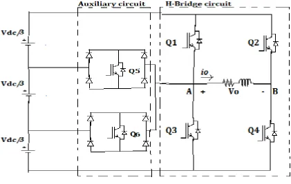
The Figure 2. Shows the 7-level inverter topology. it consist of an additional switch Q6 and four
more diodes which is responsible for producing extra 2 levels than the 5-Level Inverter so in total it had 6 switches and 8 diodes. If single DC input used than 3 capacitor used as voltage divider and if separate DC used as shown in Figure 2, then no need to use capacitor. In this paper PV Arrays used in place of separate DC source. The 7-Levels i. e. +Vdc, +2Vdc/3, +Vdc/3, 0, -Vdc, -Vdc/3 & -2Vdc/3 is created using the 6 switches and 8 diodes present in circuit. The operation of the circuit and the voltage levels is decided using particular combination of switches which is explained in table below:
Figure 2: 7-Level Inverter Topology
Output
Volage/Thyristor
Q1 Q2 Q3 Q4 Q5 Q6
+Vdc 1 0 0 1 0 0
+Vdc/3 0 0 0 1 0 1
+2Vdc/3 0 0 0 1 1 0
Available Online at www.ijpret.com 1188
-2Vdc/3 0 1 0 0 0 1
-Vdc/3 0 1 0 0 1 0
-Vdc 0 1 1 0 0 0
Table 2: Various output obtained by ON/OFF Switching Conditions of Switches in 7-Level inverter
MODULATION TECHNIQUE
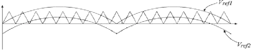
Modulate means to change the quality and here the width of output waveform is changed. To change the width of output pulse, Pulse Width Modulation (PWM) Technique is adopted. In this paper Sinusoidal Pulse Width Modulation Technique out of several PWM Technique is used were instead of maintaining the width of all pulses the same as in the case of multiple-pulse modulation, the width of each pulse is varied in proportion to the amplitude of a sinewave evaluated at the center of the same pulse. In SPWM technique reference sinusoidal wave is compared with carrier triangular wave whenever the reference signal goes above the carrier signal, pulse is generated. No of carrier wave per sinusoidal wave and the amplitude of sinusoidal wave decides the pulse width and number of pulses per cycle. In this paper two sinusoidal waves having different offset value are compared with one triangular wave to get 5-Levels in Inverter and three sinusoidal waves having different offset value are compared with one triangular wave to get 7 levels in Inverter.
Figure 3: Comparison of two sinusoidal reference waves and a triangular wave to get 5-Levels in Inverter
SIMULATION RESULTS
Available Online at www.ijpret.com 1189 complexity, THD and Efficiency. Simulation is done using Sinusoidal Pulse Width Modulation (SPWM) Technique.
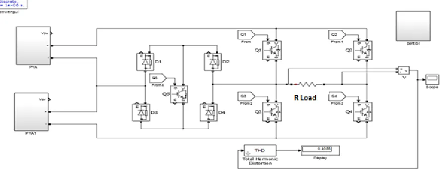
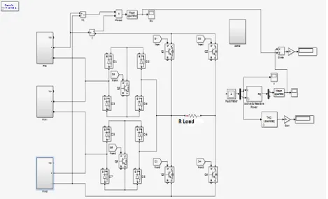
Figure 4: Simulated circuit of 5-Level Inverter
Available Online at www.ijpret.com 1190
Figure 6: Simulated circuit of 7-Level Inverter
Figure 7: 7-Levels obtained after simulation
Inverters/Parameters 5-Level Inverter 7-Level Inverter
THD 40.85% (more) 23.21% (less)
Efficiency 93.53% 97.11%
No. Of Switches In Cascaded H- Bridge
8 12
Available Online at www.ijpret.com 1191
No. Of Diodes 4 8
Cost Low High
Complexity of Circuit Low High
Table 3: Comparative results of 5-Level and 7-Level Inverter
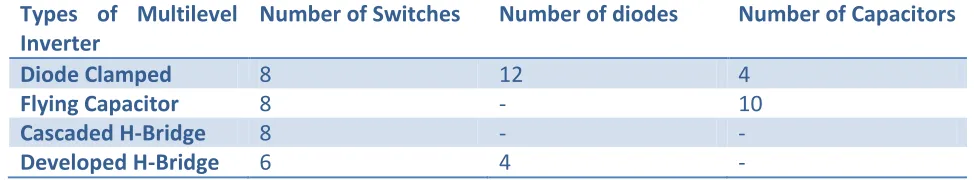
Types of Multilevel Inverter
Number of Switches Number of diodes Number of Capacitors
Diode Clamped 8 12 4
Flying Capacitor 8 - 10
Cascaded H-Bridge 8 - -
Developed H-Bridge 6 4 -
Table 4: Comparison of different types of inverters and the components used to obtain 5-Level in Inverter
CONCLUSION
Study of Multilevel Inverter specifies the different topologies which have been introduced. The comparison of 5-Level and 7-Level shows that with the increase in level multilevel inverters promises various advantages like efficiency, lower THD etc but it have certain drawbacks also like complexity and cost which increases with the increase in levels but this drawback can be eliminated with the help of new topology used.
REFERENCES
1. Muhammad H. Rashid, Power Electronics circuits, devices, and applications 2004 by Pearson education Inc
2. Divya Subramanian, Rebiya Rasheed, “Nine-Level Cascaded H-Bridge Multilevel Inverter”, International Journal of Engineering and Innovative Technology (IJEIT) Volume 3, Issue 3, September 2013
Available Online at www.ijpret.com 1192 4. T. Porselvi and Ranganath Muthu, “SEVEN-LEVEL THREE PHASE CASCADED H- BRIDGE INVERTER WITH A SINGLE DC SOURCE”, ARPN Journal of Engineering and Applied Sciences, VOL. 7, NO. 12, DECEMBER 2012 ISSN 1819-6608
5. Hong Zheng, Baohua Zhang and Lingkui Chen. 2010. “Carrier Overlapping- switching Frequency optional PWM Method for Cascaded Multilevel Inverter”. In: International Conference on Electrical and Control Engineering. 25-27 June. pp. 3450-3453.
6. Gobinath.K1 , Mahendran.S2, Gnanambal.I, “NEW CASCADED H-BRIDGE MULTILEVEL INVERTER WITH IMPROVED EFFICIENCY”, International Journal of Advanced Research in Electrical, Electronics and Instrumentation Engineering Vol. 2, Issue 4, April 2013
7. G. Laxminarayana1,K.pradeep,Comparative Analysis of 3-, 5- and 7-Level Inverter Using Space Vector PWM”, International Journal of Advanced Research in Electrical, Electronics and Instrumentation Engineering Vol. 2, Issue 7, July 2013
8. Rajesh Kr Ahuja1, Lalit Aggarwal2, Pankaj Kumar3, “Simulation of Single Phase Multilevel Inverters with Simple Control Strategy Using MATLAB”, International Journal of Advanced Research in Electrical, Electronics and Instrumentation Engineering (An ISO 3297: 2007 Certified rganization) Vol. 2, Issue 10, October 2013.
9. Prof.A.S MANE , “PERFORMANCE ANALYSIS OF MULTILEVEL INVETER” , Journal of Electronics and Communication Engineering (IOSR- JECE) ISSN: 2278-2834-, ISBN: 2278-8735, PP: 47-51
10.P. Thongprasri, “A 5-Level Three-Phase Cascaded Hybrid Multilevel Inverter”, International Journal of Computer and Electrical Engineering, Vol. 3, No. 6, December 2011
11.T. Singaravelu1, M.Balasubramani2, J .Gowrishankar3S, “Design and Implementation of Seven Level Cascaded H-Bridge Inverter Using Low frequency transformer with Single DC Source”, International Journal of Engineering and Technology (IJET)
12.Saipadhma.S1 Sangeetha.S2 Kannabiran.A3, “Comparison of Modulation Techniques for Cascaded and Reverse Voltage Multilevel Inverter Topologies”, International Journal of Advanced Trends in Computer Science and Engineering, Vol.2 , No.2, Pages : 261- 266 (2013)
Available Online at www.ijpret.com 1193 14.Alexander Varschavsky, Juan Dixon, Senior Member, IEEE, Mauricio Rotella,and Luis Morán, Fellow, IEEE, “Cascaded Nine-Level Inverter for Hybrid-Series,Active Power Filter, Using Industrial Controller”, IEEE TRANSACTIONS ON INDUSTRIAL ELECTRONICS, VOL. 57, NO. 8, AUGUST 2010
15.José Rodríguez, Senior Member,IEEE, Jih-Sheng Lai, Senior Member, IEEE, and Fang Zheng Peng, Senior Member, IEEE, “Multilevel Inverters: A Survey of Topologies, Controls, and Applications”, IEEE TRANSACTIONS ON INDUSTRIAL ELECTRONICS, VOL. 49, NO. 4, AUGUST 2002
16.Roberto González, Eugenio Gubía, Member, IEEE, Jesús López, Member, IEEE, and Luis Marroyo Member, IEEE, “Transformer less Single-Phase Multilevel-Based Photovoltaic Inverter”, IEEE TRANSACTIONS ON INDUSTRIAL ELECTRONICS, VOL. 55