Criticality Analysis of the Elements of the Light Commercial
Vehicle Steering Tie-Rod Joint
Ćatić, D. – Jeremić, B. – Djordjević, Z. – Miloradović, N.
Dobrivoje Ćatić* – Branislav Jeremić – Zorica Djordjević – Nenad Miloradović University of Kragujevac, Faculty of Mechanical Engineering, Serbia
The introduction of the paper gives the basic concepts of Failure Modes, Effects and Criticality Analysis - FMECA. Features of elements of mechanical systems regarding failure intensity demand a special approach of quantitative FMECA. The paper presents this approach, applied to the elements of mechanical systems and used for the design of a software package. Criticality analysis of failure modes of light commercial vehicle’s steering tie-rod joint elements was conducted based on the exploitation results and with the use of the previously mentioned method and program. In conclusion, the possibilities of application of the obtained results are presented.
© 2011 Journal of Mechanical Engineering. All rights reserved.
Keywords: reliability, FMECA, steering system of a light commercial vehicle, tie-rod joint
0 INTRODUCTION
According to the IEC standard [1], Failure Modes and Effects Analysis (FMEA) is a method for analysis of technical systems reliability. FMEA may be defined as a systematic set of data intended for [2] and [3]: identification and assessment of potential product failures and their effects; determination of measures and activities for elimination or reduction of the possibility for failure to occur and documentation of the previous two procedures.
FMEA was developed for USA military purposes as a technique for the assessment of reliability through the determination of effects of different failure modes of technical systems.
This method dates from November 9th, 1949, as an official document in a form of an American military standard, denoted as MIL-P 1629 and named as “Procedure for conduction of analysis of modes, effects and acuteness of failures” [3]. Application of FMEA in automotive industry projects followed no sooner than in the second half of the 1980’s and it was related with the introduction of quality regulations Q-101 by American Ford Company. Different extensions of FMEA and customizations of the FMEA method for application in automotive industry were conducted within these activities.
FMEA is a procedure for the evaluation of reliability of a technical system that may be applied in all phases of its lifetime [4]. FMEA is generally an inductive method. It is based
on the consideration of all potential failures of constitutive parts of the system and effects they have on the system. Criticality Analysis (CA) is a procedure for the evaluation of criticality rating for all constitutive parts, where, by criticality, a relative measure of item failure modes influence on reliable and safe operation of the system is meant. Joint FMEA and CA analysis are called Failure modes, effects and criticality analysis - FMECA. According to previous considerations, the application of FMECA based on exploitation data is founded on the assumption that the intensity of all failure modes of system elements is constant, which is valid for electronic systems [5]
and [6]. This assumption considerably simplifies
the procedure for criticality assessment. However, the application of this methodology in cases when failure intensity is a function of time may lead to distortion of the real picture of elements’ criticality. A proposal for the procedure of quantitative FMECA of machine system elements, originating from modification of the existing method, is given in book [7].
Element criticality analysis is extremely important for the systems with serial connection between elements (as in the vehicle steering system), where failure of any element leads to a
failure of the entire system. The steering system is
one of the vital parts of a motor vehicle complex
mechanical system [8]. Together with the braking
system and the tires, it has a crucial significance for safety of motor vehicles and people in traffic.
that are set before the steering system regarding reliability.
1 QUANTITATIVE FMECA PROCEDURE FOR MACHINE SYSTEMS’ ELEMENTS
Depending on the requirements and the possibilities for supplying the corresponding data, FMECA may be performed quantitatively and qualitatively [5]. Uniqueness of the machine system elements regarding failure intensity and objective impossibility to determine failure intensity for every possible element failure as the function of time, require special treatment during quantitative FMECA. Quantitative FMECA of machine system elements is defined in four steps:
1. Determination of criticality of failure mode j of element i is to be done by categories of failure effects k (k = 1, ..., 4), using:
C
t
t
ijk ij ij
k i
sri
( )
=
α β
⋅
( )⋅
,
(1)where αij is a relative rate (frequency measure) of
failure mode j of element i (0 ≤ αij ≤ 1, αij j
∑
=1),βij( )k is conditional probability that failure mode
j of element i will cause category k failure effect according to the adopted classification (values are
taken from Table 1, according to recommendations
from [5] and [6]), ti is operating time of element
i and tsri is mean operating time until failure of
element i occurs.
Table 1. Values of conditional probabilities
Degree of occurrence of the kth
failure effect category βij( )k [-]
Certain event 1
Probable event 0.1 ... 1
Most probably would not happen 0 ... 0.1 Practically does not happen 0
The calculated values of Cij( )k are the initial basis for determining other quantitative properties
of element criticality. They make it possible to
rank element failure modes according to effects in order to evaluate the most critical system’s failure modes from the aspect of safety.
2. Determination of failure criticality of element i, which causes the kth category of failure effects:
Cik Cijk j
( )=
∑
( ). (2)The calculation of Ci( )k enables the isolation of the most important elements whose failures lead to certain categories of effects.
3. Determination of “absolute criticality” of element i according to:
C a Ci = 1 i( )1 +a C2 i( )2 +a C3 i( )3 +a C4 i( )4, (3)
where ak is “weight” of the kth category of effects
(values may be determined using subjective evaluation of the effect’s “weight” for each case, from the interval between 0 and 1) and Ci( )k is the
ith element criticality for the kth category of effects. System element criticality rate may be evaluated indirectly, by ranking of acquired values; there is no need for additional complicated analysis when safety and duration aspects are in scope.
4. Determination of criticality of the kth category of the system’s effects, by summation of criticalities of all elements failure modes for the specified effect category:
Ck Cijk
j i
=
∑
∑
( ). (4)Calculated values of Ck are statistical
indicators of the representation rating of the individual category of effects.
According to the suggested methodology, mean operating time until element failure occurs is one of the basic parameters for determining element criticality. Differences between machine elements in regard to reparability, the percentage of failure occurrence in the system’s total operating time, belonging to appropriate structural set, etc., require a special approach in the definition of mean operating time until failure; the calculated element criticalities according to this parameter will then be comparable [7].
Fortran 77 software package was developed
for FMECA of machine system elements. This
2 TIE-ROD JOINT AS A COMPONENT PART OF MOTOR VEHICLE’S STEERING SYSTEM
The motor vehicle steering system is a
mechanical system that has to meet high demands of reliability [8]. Importance of the motor vehicle steering system for human safety requires a detailed analysis of structural components in view of occurrence of their failure during exploitation.
The steering system of the wheeled vehicle
contains two basic subsystems: the steering mechanism (group of steering wheel’s column) and the steering linkage (group of tie-rods and steering arms).
In addition to connecting the steering mechanism and the steered wheels, steering linkage has a very important task to provide
proper kinematics of the wheel turn. This means
that the steering linkage must be completely in accord with the suspension system of the steered wheels, so the motion of the wheels relative to the vehicle frame, does not influence the safety
of steering. The previously given task is obtained
by designing the linkage system in the form of trapeze.
The steering linkage of a light commercial
vehicle’s steering system with one-piece cross tie-rod is presented in Fig. 1 [9].
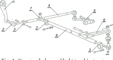
Fig. 1. Steering linkage of light truck’s steering system
Torque is transmitted from the output shaft
of the steering gear, through the steering arm (1) and the drag arm (consisting of a drag arm joint (2), a clamp (3) and a drag link with joint (4)), to a drag link steering arm (5) on the front left wheel. Drag link steering arm is connected to the wheel spindle by bolts. On the lower side of the left wheel spindle, there is an arm (6) that transfers the force through a cross-link (consisting of joints (7),
clamps (3) and cross tube (8)), to the identical link
at the right wheel spindle. The front axle, wheel
arms (6) and the cross tube form the steering trapeze.
In order to achieve the basic function of the steering system - turning the wheels at a given angle, the linkage mechanisms must never be rigid constructions. Spherical joints are the most convenient links between the elements due to a complex relative motion of the elements of the steering linkage system during turn.
Spherical joints provide mobility in all
three planes. There must not be any clearance
in the tie-rod joint in order to preserve proper steering kinematics. Cancelation of clearance is achieved by designing the joint cup in two parts, so the upper moving part of the cup presses the ball pin sphere with the help of a spring.
The elements of the tie-rod joint used in the
light truck steering systems are shown in Fig. 2.
Fig. 2. Tie-rod joint: 1 - Joint’s body, 2 - Ball pin,
3 - Cup, 4 - Spring, 5 - Cover, 6 - Sealing cap,
7 - Nut
By analysis of modes, effects and criticality
of failures of the steering system elements built in light commercial vehicles, it has been established that the tie-rod joints are the most critical elements from the aspect of reliability and safety [7].
3 CRITICALITY DEGREE ANALYSIS OF THE TIE-ROD JOINT’S ELEMENTS
Due to indisputable importance that the tie-rod joint has in a reliable and safe operation of the motor vehicle steering system, quantitative criticality analysis of this structure was conducted
starting at the level of elements. The basis for
this analysis was a complex data structure in the
form of a table data sheet. The procedure for the
of the tie-rod joint of the light commercial vehicle steering system consisted of the following steps: 1. Structural system division, identification and
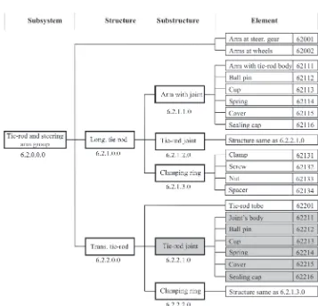
coding of constitutive elements of the tie-rod joint was done within the structural division of the group of tie-rods and steering arms of light commercial vehicle steering system (Fig. 3);
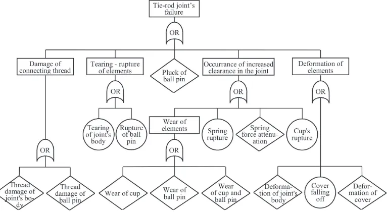
2. Identification and recording of the most tie-rod joint elements failure modes were performed by forming the fault tree shown in Fig. 4;
3. Determination of relative share of individual element failure modes;
4. A category definition of final failure effects (all failure mode effects of the steering system tie-rod joint elements are classified in four categories: the first category is of the highest rank, and the fourth category is of the lowest rank);
5. Categorization of element failure modes according to effects and determination of conditional probabilities of final effects occurrence;
6. Determination of mean operating time until element failure occurs and
7. The calculation of total operating time of an
element (equal for all tie-rod joint elements).
The fault tree of the tie-rod joint presented
in Fig. 4 was obtained using symbols for events and logical gates [2]. A rectangle represents the peak or intermediary event in the fault tree, a triangle - primary basic event and a rhomb - secondary basic event. Of all logical gates, only
a symbol for logical gate OR was used, which
produces an output event if one or more input events occur.
Systems and elements of a motor vehicle are loaded with variable loads in the course of
time. The total number of load variation cycles
is proportional to the distance passed. Thus,
time until failure of the most elements of motor vehicles occurs is measured in kilometres of
distance passed. Tie-rod joints belong to the
group of machine elements whose durability is limited by durability of the critical elements in the structure. Durability of the tie-rod joint is limited by durability of the sliding surfaces of the ball pin
and the cup. The estimated mean operation time
until failure occurs is 100,000 km [10].
Elements of the tie-rod joint belong to the group of machine elements in which failure modes occur only in a certain number of them. In that case, it is assumed that the rest of elements that did not fail have the mean time before the failure occurs equal to the mean time until failure of structure occurs. Eq. (5) was used for the calculation of mean time until failure of the tie-rod joint element occurs in kilometres of distance travelled [7].
ssr p sj srj p s
j n
j j
n
srs
= ⋅ + −
⋅
= =
∑
∑
1
100 1 100 1
, (5)
where ssrj is mean operation time of the tie-rod
joint elements that have failed in the jth mode, n is the number of different element’s failure modes,
pj is percentage rate of the jth failure mode in total
number of structure elements failures, ssrs is mean
time before structure failure occurs.
Operation time, ti, from Eq. (1), is usually
expressed in hours. Since criticality is a non-dimensional value, it is necessary to express the mean time until element failure occurs in the same units as ti. Transformation of mean time
until failure of the tie-rod joint elements occur expressed in kilometres of the distance travelled into mean operation time in hours is conducted by the adoption of mean vehicle velocity of 60 km/h.
Table 2 contains data used to form input files for FMECA.FOR program. To calculate
the elements absolute criticality, the following weighting factors of effect categories are adopted:
a1 = 1; a2 = 0.5; a3 = 0.3; a4 = 0.2. Weighting factors were adopted by subjective assessment of the experts from the subject area.
Designation Q in Table 2 is for quantity or
number of identical elements within the scope of discussed object of analysis.
By processing the acquired data and by
using the computer program, output lists are gained for the degree of criticality of the tie rod joint elements failure modes without taking
into account the effects (Table 3), the degree of
criticality of the tie rod joint elements with taking
into account the effects (Table 4), the degree of
absolute criticality of the tie rod joint elements
(Table 5) and the degree of criticality of final failure effects of the tie rod joint elements (Table
6).
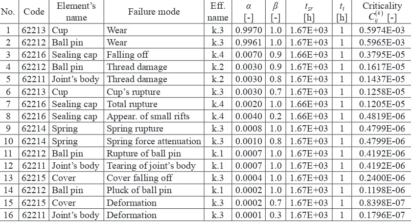
The total number of 16 different failure
modes was discussed during estimation of criticality degree of the failure mode of
tie-rod joint elements. Based on Table 3, the most
critical failure mode of the tie-rod joint elements regardless the effects is wear of the cup and the ball pin. Its criticality is almost 160 times higher
than criticality of the next failure mode in the
descending order from the Table 3.
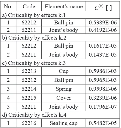
Based on criticality degree of the tie-rod
joint elements with taking into account the effects
(Table 4), it may be seen that, in severe categories
of effects, only failure modes of the ball pin and the joint’s body occur, but with relatively small
Table 2. Basics of the FMECA procedure for elements of the tie rod joint for light commercial vehicles
Element’s
name Elem. code [-]Q Failure mode
Failure mode
code
Rel.
rate
αij[-]
Loss prob.
βij [-]
Final effect
ssri
×103 [km]
ssr
×103 [km]
tsr
×103 [h] Joint’s
body 62211 1 DeformationTearing of joint’s body Thread damage
N.02 N.06 N.07
0.0001 0.0007 0.003
0.3 1.0 0.8
k.3 k.1 k.2
200 200 100
100 1.67
Ball pin 62212 1 Rupture of ball pin Thread damage
Pluck of ball pin Wear
N.06 N.07 N.29 N.77
0,0007 0.0030 0.0002 0.9961
1.0 0.9 1.0 1.0
k.1 k.2 k.1 k.3
200 100 100 100
100 1.67
Cup 62213 1 Cup’s rupture
Wear N.06N.77 0.0030.997 0.71.0 k.3k.3 150100 100 1.67 Spring 62214 1 Spring rupture
Spring force attenuation N.06N.12 0.00080.001 1.00.8 k.3k.3 20020 100 1.67 Cover 62215 1 Deformation
Cover falling off N.02N.29 0.00020.0004 0.71.0 k.3k.3 100200 100 1.67 Sealing
cap 62216 1 Total ruptureFalling off
Appearance of small rifts
N.06 N.29 N.37
0.002 0.007 0.004
1.0 0.9 0.2
k.4 k.4 k.4
30 150
20
99.89 1.66
Table 3. Criticality of elements’ failure modes without taking into account the effects
No. Code Element’s name Failure mode nameEff. [-]α [-]β tsr
[h] [h]ti CriticalityCij( )k [-]
1 62213 Cup Wear k.3 0.9970 1.0 1.67E+03 1 0.5974E-03
2 62212 Ball pin Wear k.3 0.9961 1.0 1.67E+03 1 0.5965E-03
3 62216 Sealing cap Falling off k.4 0.0070 0.9 1.66E+03 1 0.3795E-05 4 62212 Ball pin Thread damage k.2 0.0030 0.9 1.67E+03 1 0.1617E-05 5 62211 Joint’s body Thread damage k.2 0.0030 0.8 1.67E+03 1 0.1437E-05
6 62213 Cup Cup’s rupture k.3 0.0030 0.7 1.67E+03 1 0.1258E-05
7 62216 Sealing cap Total rupture k.4 0.0020 1.0 1.66E+03 1 0.1205E-05 8 62216 Sealing cap Appear. of small rifts k.4 0.0040 0.2 1.66E+03 1 0.4819E-06 9 62214 Spring Spring rupture k.3 0.0008 1.0 1.67E+03 1 0.4799E-06 10 62214 Spring Spring force attenuation k.3 0.0010 0.8 1.67E+03 1 0.4799E-06 11 62212 Ball pin Rupture of ball pin k.1 0.0007 1.0 1.67E+03 1 0.4192E-06 12 62211 Joint’s body Tearing of joint’s body k.1 0.0007 1.0 1.67E+03 1 0.4192E-06 13 62215 Cover Cover falling off k.3 0.0004 1.0 1.67E+03 1 0.2400E-06 14 62212 Ball pin Pluck of ball pin k.1 0.0002 1.0 1.67E+03 1 0.1198E-06
15 62215 Cover Deformation k.3 0.0002 0.7 1.67E+03 1 0.8398E-07
values of criticality. For effect k.3, the cup and the pin-ball have criticality degree of order 10-3, while criticality degrees of other elements have orders of 10-6 and less. Generally, element failure modes with effect k.4, regardless of occurrence, are not authoritative for determining the most critical parts of the observed object.
Table 4. Criticality of elements with taking into account the effects
No. Code Element’s name Ci( )k [-] a) Criticality by effects k.1
1 62212 Ball pin 0.5389E-06
2 62211 Joint’s body 0.4192E-06 b) Criticality by effects k.2
1 62212 Ball pin 0.1617E-05
2 62211 Joint’s body 0.1437E-05 c) Criticality by effects k.3
1 62213 Cup 0.5986E-03
2 62212 Ball pin 0.5965E-03
3 62214 Spring 0.9598E-06
4 62215 Cover 0.3239E-06
5 62211 Joint’s body 0.1796E-07 d) Criticality by effects k.4
1 62216 Sealing cap 0.5482E-05
Table 5. Absolute criticality of elements
No. Code Element’s name ci [-]
1 62212 Ball pin 0.1803E-03
2 62213 Cup 0.1796E-03
3 62211 Joint’s body 0.1143E-05 4 62216 Sealing cap 0.1096E-05
5 62214 Spring 0.2879E-06
6 62215 Cover 0.9718E-07
Table 6. Criticality of final failure effects
No. Final effect Ck [-] Rel. crit. [%]
1 k.3 0.1196E-02 99.21
2 k.4 0.5482E-05 0.45
3 k.2 0.3054E-05 0.25
4 k.1 0.9581E-06 0.08
Table 5 contains elements of the tie-rod ranked by absolute criticality. The ball pin and the
joint’s cup have the highest absolute criticality,
followed by the joint’s body, the sealing cap, the spring and the cup.
The other way of determining the most
critical elements of the steering tie-rod joint is
comparative analysis of Tables 6 and 4. In Table
6, there is obvious predominant occurrence of elements’ failure modes with category of effect
equal to three. 99.21% of total sum of elements’
criticality are elements’ failure modes with third
category of effects. Table 4 contains the elements
ranked by criticality and by category of effects. For effect k.3, the most critical elements are the cup and the ball pin of the tie-rod joint. Fig. 5 shows distribution of criticality degree of the tie-rod elements for effect category k.3.
Fig. 5. Distribution of degree of criticality for
elements of the steering system’s tie rod joint for category of effects k.3
As it may be seen in Fig. 5, failure of the tie-rod joint in the largest number of cases appears due to failure of the cup or the ball pin, while
only 0.11% is due to other elements. A similar
conclusion may be reached by analysis of absolute
criticality of elements (Table 5).
4 CONCLUSIONS
A lot of the information necessary for taking measures in order to eliminate detected defects may be obtained by forming the databases of machine system element failures during exploitation and by their processing. Determining critical elements of mechanical systems that limit reliable and safe operation of the system and taking corrective measures in order to reduce the acuteness, present the fastest and the cheapest way to increase reliability and, accordingly, the product‘s quality.
The use value of FMECA results is in
proportion to volume and credibility of the
initial data. This points to the need that every
company should form an information system for the acquisition and processing of data on errors, defects and failures of company‘s products. An organised system for data acquisition must provide continuous flow of data, their processing and availability. In order to get complex and credible database on modes, causes, effects and operation periods before failure of mechanical systems or elements occurs, data must be acquired in the design phase, development phase and in product‘s exploitation.
Parameters of durability (relative frequency of failure occurrence and mean operation time until failure) and parameters of safety (probability of failure effect occurrence - quantitative in nature and failure effect categories - qualitative in nature) have an influence on the criticality of machine system elements in exploitation. As far as quantitative indices are concerned, by analysis of intervals of possible parameter values, it may be concluded that parameters of durability have a dominant influence on the criticality of
elements. This is another reason for the criticality
of elements, defined according to the given methodology, to be the basis for determination of critical elements that have limiting effect on machine system’s reliability.
Generally, the machine system level
of reliability can be increased by increasing the reliability of constitutive components or by introducing the parallel connections. Due to space limitations in motor vehicles steering systems, it is not possible to introduce parallel connections, so the only possibility to increase the
system’s reliability is through the increase of each component’s reliability.
5 REFERENCES
[1] IEC 60812. (2006). Analysis techniques for system reliability - Procedure for failure mode and effects analysis (FMEA). 2nd ed., Geneva, International Electromechanical Commission. [2] Lazor, D.J. (1995). Failure mode and effects
analysis (FMEA) and fault tree analysis
(FTA). Handbook of Reliability Engineering and Management, McGraw-Hill, New York,
p. 6.1-6.46.
[3] Stamatis, D.H. (2003). Failure mode and effect analysis. 2nd ed., American Society for Quality, Milwaukee.
[4] Popović, V., Vasić, B., Petrović, M. (2010). The possibility for FMEA method
improve-ment and its impleimprove-mentation into bus life cycle. Strojniški vestnik - Journal of
Mechanical Engineering, vol. 56, no. 3, p. 179-185.
[5] Military standard MIL-STD-1629A (1980).
Procedures for Performing a Failure Mode.
Effects and Criticality Analysis Department of Defense, Washington.
[6] Mtain Inc. Reliability, maintainability,
logi-stics support, engineering services, reliability failure modes, effects and criticality analysis, from http://www.mtain.com/relia/relfmeca. htm, accessed on 2010-06-08.
[7] Ćatić, D. (2005). Development and
applica-tion of reliability theory methods, Faculty of Mechanical Engineering, Kragujevac.
[8] Janićijević, N., Janković, D., Todorović, J.
(1998). Design of motor vehicles. Faculty of
Mechanical Engineering, Belgrade.
[9] Service manuals. (1991). Zastava Iveco
trucks, Kragujevac.
[10] Ćatić, D., Krstić, B., Miloradović, D. (2009).
Determination of reliability of motor vehicle’s steering system tie-rod joint. Journal of the
Balkan Tribological Association, vol. 15, no.
3, p. 309-322.
[11] Soković, M., Jovanović, J., Krivokapić, Z., Vujović, A. (2009). Basic quality tools in
continuous improvement process. Strojniški
vestnik - Journal of Mechanical Engineering,