Trans. Phenom. Nano Micro Scales, 7(1): 1-8, Winter and Spring 2019 DOI: 10.7508/tpnms. 2019.01.001
.
Multi-objective optimization of nanofluid flow in microchannel heat sinks with
triangular ribs using CFD and genetic algorithms
Hamed Safikhani1,2,*, Saeed Mahdavifar1,2
1Department of Mechanical Engineering, Faculty of Engineering, Arak University, Arak 38156-88349, Iran
2Institue of Nanosciences & Nanotechnolgy, Arak University, ARAK, Iran
Received 24 November 2016; revised 13 March 2017; accepted 1 May 2017; available online 30 January 2019
ABSTRACT: In this paper, multi-objective optimization (MOO) of Al2O3-water nanofluid flow in microchannel heat sinks (MCHS) with triangular ribs is performed using Computational Fluid Dynamics (CFD) techniques and Non-dominated Sorting Genetic Algorithms (NSGA II). At first, nanofluid flow is solved numerically in various MCHS with triangular ribs using CFD techniques. Finally, the CFD data will be used for Pareto based multi-objective optimization of nanofluid flow in MCHS with triangular ribs using NSGA II algorithm. In the MOO process there are seven geometrical and non-geometrical parameters and the conflicting objective functions are to simultaneously maximize the amount of heat transfer and minimize the pressure drop. Five optimum designs are determined and discussed for both nanofluid and base fluid flows. Details of design variables for each of five optimum points are deeply discussed. It is shown that the achieved Pareto solution includes important design information on nanofluid flow in MCHS with triangular ribs.
KEYWORDS: Microchannel heat sink (MCHS); multi-objective optimization (MOO); nanofluid; NSGA II
INTRODUCTION
The developing mechanisms of cooling technique for high heat flux electronic modules was started with Tuckerman's first applied on microchannel heat sink (MCHS) using silicon device around 1980s [1]. The traditional rectangular MCHS has the characteristics of small mass and volume, large convective heat transfer coefficient and high surface area to volume ratio. However, the lowly fluid mixing and boundary layer thickening in the flow direction of conventional MCHS give growth to the need for enhancing the heat transfer [2]. Recently researchers are developing new cooling techniques that are capable of enhancing high-heat flux rate for microelectronic applications [2-15]. The heat transfer coefficient could be enhanced by achieving thinner fluid boundary layer thickness, promoting mixing of main flow at near wall region, and raising the turbulence intensity by creating rotating secondary flow. However, the techniques that were employed to enhance these effects usually result in high pressure drop [3]. In recent years, Xu et al. [4, 5] had investigated the microscale heat transfer enhancement using the thermal boundary layers redeveloping concept. The research composed of parallel longitudinal microchannels and several transverse microchannels. The transverse microchannel is used to separate the whole flow length into several independent zones. They found out that the computed hydraulic and thermal boundary layers were redeveloping in each separated zonedue to shortened overall flowlength for the interrupted MCHS.dary
*Corresponding Author Email: [email protected]
Tel.: +989120686211; Note. This manuscript was submitted on November 24, 2016; approved on May 1, 2017; published online January 30, 2019.
The pressure drop characteristics and the heat transfer performance were shown to be enhanced with the interrupted MCHS design as compared to the conventional MCHS design.
Among others, Cheng [6] investigated the flow characteristics and heat transfer of a stacked two-layer MCHS with multiple MEMS easy-processing passive microstructures. The effect of the ratio of embedded structure height to microchannel height was studied. It is found out that with the boundary layer redevelopment concept, the proposed MCHS with passive structures has better performance than straight rectangular MCHS. Investigation on three-dimensional interrupted MCHS with rectangular ribs in the transverse microchambers has also been successfully demonstrated by Chai et al. [9] through experiment and numerical methods. They inspected the pressure drop and heat transfer characteristics of various dimensions and positions of the rectangular ribs in the transverse microchambers. Wong and Lee [2] investigated the numerical simulation of flow field in MCHS with triangular ribs in the transverse microchamber. They performed a parametric study and finally presented a microchannel with optimum performance.
One of the other effective ways for increasing the heat transfer in tubes is to use the nanofluid instead of base fluid. Nanofluid is a mixture created from adding nanoparticles, such as Al2O3 or CuO to a base fluid and it gives rise to increasing the mixture thermal conductivity as well as heat transfer in tubes.
ORIGINAL RESEARCH PAPER
Nomenclature
Greek Symbols
a Acceleration (m s-2) α Thermal diffusivity (=k/ρC
p),(m2 s-1) p
C Specific heat (J kg-1 K-1) β Volumetric expansion coefficient (K-1) f
C Skin friction coefficient (-) δ Distance between particles (m) C Constant in eq. 14 Φ Nanoparticles volume fraction (-)
p
d Diameter of nanoparticles (m) λf Mean free path of water molecular (m) g Gravitational acceleration (m s-2) μ Dynamic viscosity (N s m-2)
k Thermal conductivity (W m-1 K-1) ν Kinematic viscosity (m2 s-1) B
k Boltzmann constant (=1.3807
×
10-23 J/ K) ρ Density (kg m-3) 1L Length of the triangular ribs τw Wall shear stress (Pa) 2
L Half of the rectangular fin thickness Subscripts
3
L Half of the triangular rib width BF Base fluid 4
L Axial space between two following fin CT Circular tube
5
L Half of micro channel duct dr Drift Nu Nusselt Number (= hDh/k),(-) f Fluid
P Pressure (Pa) i Inlet conditions
Pr Prandtl number (=αm/νm), (-) k Indices Re Reynolds number (=VDh/νm), (-) m Mixture
T Temperature (K) BF Base fluid
V Velocity (m s-1) CT Circular tube
In recent years, many experimental and numerical studies have been done in the field of nanofluids [16-25].
Using nanofluids flowing in microchannel heat sinks with triangular ribs will result in increasing the heat transfer and pressure drop; hence, by doing a multi-objective optimization, optimal design points should be identified. In this paper, the multi-objective optimization procedure for nanofluids flow in microchannel with triangular ribs will be performed using Computational Fluid Dynamics (CFD) techniques and NSGA II algorithm.
In recent years, many researchers have applied neural networks for modeling various parameters in engineering issues [26-28]. One of the most complete and the best multi-objective optimization algorithms also used in this paper is NSGA II algorithm. This algorithm proposed by Deb [29] for the first time has been applied abundantly for the multi-objective optimization of engineering issues in recent years [30-32].
Based on our information, so far, no multi-objective optimization of micro channel heat sinks with triangular ribs cooled by nanofluid flow has been performed, with the goal of increasing amount of heat transfer and decreasing the pressure drop.
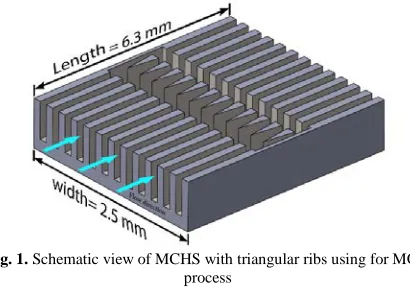
In this paper, by employing the Computational Fluid Dynamics (CFD) and applying the NSGA II algorithm, the cooling of a microchannel heat sinks with triangular ribs subjected to Al2O3-water nanofluid flow is multi-objectively optimized. Schematic of geometry and computational domain is shown in Figures 1 and 2 respectively.
In the optimization process, seven different design variables (five geometrical and two non-geometrical) are changed so as to simultaneously maximize the amount of heat transfer and minimize the pressure drop.
In the results section, the Pareto front, which simultaneously displays the changes of the heat transfer and pressure drop, will be presented, and it will be demonstrated that the Pareto front conveys very important results for the thermal designing of microchannel heat sinks with triangular ribs subjected to nanofluid flow.
Fig. 1. Schematic view of MCHS with triangular ribs using for MOO
process
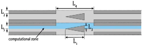
DEFINING THE DESIGN VARIABLES
In the present study there are seven independent design variables: length of the triangular ribs (L1), half of the
rectangular fin thickness (L2), half of the triangular rib width
(L3), axial space between two following fin (L4), half of the
micro channel duct (L5), inlet velocity (Vi) and nanoparticle
volume fraction (Φ).
The geometrical design variables are shown in Figure 2 and the variation range of each one is shown in Table 1.
Fig. 2. Computational domain used in MOO process
By changing the design variables according to the Table 1, various designs will be created and simulated by CFD which will be further used for Pareto based multi objective optimization of nanofluid flow parameters in microchannels with triangular heat sinks.
Table 1
Design variables and their range of variations.
Design Variables From To
m)
μ
( 1
L 100 1000
(μm)
2
L 15 200
(μm)
3
L 15 300
(μm)
4
L 100 1500
(μm)
5
L 15 150
(m/s) i
V 0.001 12.00
(%)
Φ 0 3
MATHEMATICAL MODELING
Mixture model
In the present study, numerical simulation of nanofluid flow is performed using two phase mixture model. The mixture model is a two phase numerical method that assumes local equilibrium over short spatial length scales. The two phases are treated to be interpenetrating continua, meaning that each phase has its own velocity vector field, and within a given control volume there is a certain fraction of each phase.
Instead of utilizing the governing equations of each phase separately, it solves the continuity, momentum and energy equations for the mixture, and the volume fraction equation for the secondary phases, as well as algebraic expressions for the relative velocities.
The equations for the steady state conditions and mean flow are:
Continuity equation
0
)
V
.(
m m=
∇
ρ
(1)Momentum equation
)
(
)
.(
)
.(
)
.(
, , 1, drk mi m i n k k dr k k m m m m m
T
T
g
V
V
V
P
V
V
−
−
∇
+
∇
∇
+
−∇
=
∇
∑
=β
ρ
ρ
φ
µ
ρ
(2) Energy equation)
T
k
.(
))
P
H
(
V
.(
m n 1 k k k kk
+
=
∇
∇
∇
∑
=ρ
φ
(3) Volume fraction)
V
.(
)
V
.(
φ
Pρ
P m=
−∇
φ
Pρ
P dr,P∇
(4)Where Vm is the mass average velocity and defined as
follows: m n 1 k k k k m
V
V
ρ
ρ
φ
∑
==
(5)In equation 2, Vdr,k is the drift velocity for the secondary phase k, i.e. the nanoparticles in the present paper and defined as follows:
m k k ,
dr
V
V
V
=
−
(6)The slip velocity (relative velocity) is defined as the velocity of nanoparticles relative to the velocity of base fluid:
f p
pf
V
V
V
=
−
(7)The relation between drift velocity and relative velocity is as follows: fk n 1 k m k k pf p ,
dr
V
V
V
∑
=−
=
ρ
ρ
φ
(8)The relative velocity and drag function are calculated using Manninen et al. [33] and Schiller and Naumann [34] relations respectively, as follows:
a
)
(
f
18
d
V
P m P drag f 2 P P pfρ
ρ
ρ
µ
ρ
−
=
(9) 0.6871 0.15 Re Re 1000
0.0183 Re Re 1000
P P drag P P for f for + ≤ = > (10)
The acceleration (a) in equation 9 is
m m
.
)
V
V
(
g
a
=
−
∇
(11)Nanofluid mixture properties
The mixture properties for Al2O3-water nanofluid are calcu
calculated based on following expressions:
Density [35]
f p
m
φρ
(
1
φ
)
ρ
ρ
=
+
−
(12)Specific heat capacity [36]
f p p
p m
p
)
(
C
)
(
1
)(
C
)
C
(
ρ
=
φ
ρ
+
−
φ
ρ
(13)Dynamic viscosity [37]
δ
ρ
µ
µ
C
72
d
V
2 p B p fm
=
+
(14)Where VB and δ are Brownian velocity of nanoparticles
and distance between particles respectively, which can be calculated from: p p B p B
d
T
k
18
d
1
V
πρ
=
(15) p 3d
6φ
π
δ
=
(16)C in equation 14 is defined as:
f 4 p 3 2 p
1d C ) (C d C )
C ( C
µ
φ
+ ++
= (17)
Where C1, C2, C3 and C4 are given as:
000000393 . 0 , 00000009 . 0 , 000002771 . 0 , 000001133 . 0 4 3 2 1 − = = = − − = C C C C (18)
Thermal conductivity [38]
2321 . 1 9955 . 0 7476 . 0 3690 . 0 7460 . 0
Re
Pr
)
(
)
(
7
.
64
1
f f f p p f f mk
k
d
d
k
k
=
+
φ
(19)
Where Prf and Ref are defined as:
f f f
Pr
α
ρ
η
=
(20) f 2 B f3
T
k
Re
λ
πη
ρ
=
(21)Where λf is mean free path of water molecular (λf = 0.17
nm), kB is Boltzmann constant (kB= 1.3807 × 10⁻²³ J/K) and
η has been calculated by the following equation:
140 , 8 . 247 , 10 414 . 2 , 10 . 5 = = × = = − − C B A
A T C
B
η
(22)
Thermal expansion coefficient [39]
f f p f p p f m 1 1 1 ) 1 ( 1 1
β
ρ
ρ
φ
φ
β
β
φρ
ρ
φ
β
− + + − + = (23)BOUNDARY CONDITIONS
For numerical simulation, the equations of previous sections should be solved subject to the following boundary conditions:
Tubes inlet
i
V
V
=
(24a)i T
T= (24b)
i
φ
φ
=
(24c)Fluid-wall interface
0
=
V
(25a) w m wn
T
k
q
∂
∂
−
=
′′
(25b)Tubes outlet: Zero gradient is applied to hydrodynamic variables and constant gradient is applied to temperature [19, 40]:
0 dz
dVz = (26a)
Numerical methods
The numerical simulation is performed using the finite volume method. A second order upwind method is used for the convective and diffusive terms and the SIMPLE algorithm is employed to solve the coupling between the velocity and pressure fields. In the generated grid, because of the large hydrodynamic and thermal gradients, smaller grid is used near the walls and also at the tube inlet. To make sure that the obtained results are independent of the size and the number of generated grids, several grids with different sizes along different directions has been tested for each MCHS; and it has been attempted to consider for each one the best grid, with the highest accuracy and the lowest computation cost. A sample of grid generation for MOO process is shown in Figure 3.
Fig. 3. A sample of grid generation for the MCHS with triangular ribs
Moreover some other operating conditions which are used in the CFD simulations are shown in Table 2.
Table 2
Dimensions and some operating conditions for CFD simulations.
Parameter Value
MCHS length (mm) 6.3
MCHS width (mm) 2.5
) 3
Water density (kg/m 998.2 )
3 density (kg/m 3
O 2
Al 3720
Water thermal conductivity (W/m K) 0.6028 thermal conductivity (W/m K)
3 O 2
Al 35
Inlet temperature (K) 300
Validations of the numerical simulations
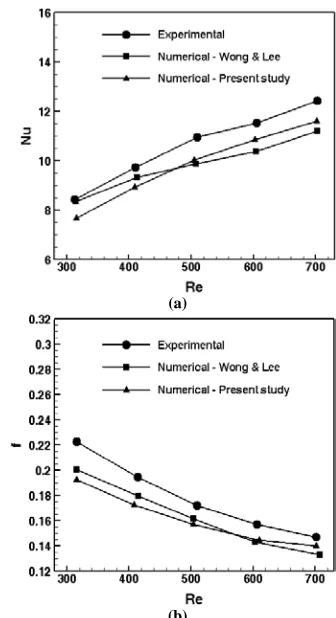
To attain the confidence about the simulations, it is necessary to compare the simulation results with the available data. Figure 4 compares the 𝑁𝑁𝑁𝑁���� and 𝑓𝑓̅ versus Re number in the present study with the experimental data of Chai et al. [9] and numerical simulations of Wong and Lee [2] for base fluid. As shown good agreement between the present simulation results and the reported experimental and numerical ones are observed.
(a)
(b)
Fig. 4. Validation of the results of (a) average Nusselt number (b)
friction factor for the MCHS with rectangular ribs
RESULTS AND DISCUSSION
In order to investigate the optimal performance of nanofluid flow in MCHSc as mentioned in Table 1, a multi-objective optimization procedure using NSGA II algorithm is used [29-30]. In all runs a population size of 60 has been chosen with crossover probability (PRcR) and mutation probability (PRmR) as 0.7 and 0.07 respectively. The two conflicting objectives in this study are QRtotalR and ∆P that should be optimized simultaneously with respect to the design variables LR1R, LR2R, LR3R, LR4R, LR5R, VRiR and Φ (Table 1). The multi-objective optimization problem can be formulated in the following form:
≤
≤
≤
≤
≤
≤
≤
≤
≤
≤
≤
≤
≤
≤
=
∆
=
(%)
3
0
)
/
(
12
001
.
0
)
(
10
2
)
(
10
2
:
)
(
10
2
)
(
10
2
)
(
10
2
)
,
,
,
,
,
,
(
)
,
,
,
,
,
,
(
5 4 3 2 1
5 4 3 2 1 2
5 4 3 2 1 1
φ
φ
φ
s
m
V
mm
L
mm
L
to
Subject
mm
L
mm
L
mm
L
V
L
L
L
L
L
f
P
Minimize
V
L
L
L
L
L
f
Q
Maximize
i
i i total
(27)
Figure 5 shows the Pareto fronts of the mentioned objective functions for both of the base fluid and nanofluid flows.
Fig. 5. Pareto optimal points for Qtotal and ∆P for base fluid and
nanofluid flows
It is clear that in both Pareto fronts the points have no dominancy over one another, meaning that no two points can be found where one of their objective functions is the same and the other one is different.
In other words, as we move from one point to another, definitely, one objective function gets better and the other one gets worse.
In each Pareto fronts (base fluid and nano fluid) five optimal points, designated by A, B, C, D and E for base fluid and An, Bn, Cn, Dn and En for nanofluid flow can be
observed in this figure, whose corresponding design variables have been presented in Table 3.
The points illustrated in Figure 5 have unique features. Points A and E (and also An and En) exhibit the least pressure
drop and the highest heat transfer value, respectively. Points B and D (and also Bn and Dn), known as the break points, are
also interesting points in the design. In fact, as we go from point A (or An) to point B (or Bn), Δpincreases very little,
while Qtotalincreases considerably. Similarly, as we go from
point E (or En) towards point D (or Dn), Qtotal increases a
little, while Δp improves by a higher value.
Table 3
The values of objective functions and their associated design variables of the optimum points.
In general, it would be ideal to find a point at which both objective functions are adequately satisfied. To find such a point, we use the mapping method [30].
For this purpose, we assume the values of both objective functions to be between 0 and 1, and calculate the norm of these functions; the point with the highest norm value constitutes the ideal design point. Points C (base fluid) and Cn (nanofluid) are the points that have been obtained from
this approach, and it can be said that they adequately satisfy both objective functions of heat transfer and pressure loss.
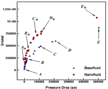
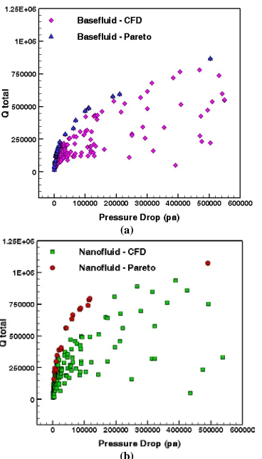
Finally, it would be interesting and useful to compare the 360 primary data obtained from the CFD simulations (180 data for nanofluid and 180 for base fluid flow) with the extracted Pareto fronts in this section. Figure 6 shows the overlap of the Pareto fronts of nanofluid and base fluid flows and the initial CFD data. This Figure indicates that the Pareto fronts have recognized very accurately the best boundary of the CFD data with respect to the lowest pressure drop and highest heat transfer value. This point also verifies the validity of the MOO process.
Point
Design Variables Objective Functions Other Parameters
L1(μm) L2(μm) L3(μm) L4(μm) L5(μm) Vi(m/s) Φ(%) Qtotal(W) ΔP(pa) ΔT(K) n
Ba
se
fl
u
id A 909 140 27 1271 75 0.083 - 16013 416.7 49.3 5
B 654 39 23 719 47 1.054 - 196943 15083 36.9 14
C 454 30 23 1331 37 7.53 - 578983 188384 20.1 18
D 451 30 16 1331 16 8.18 - 594710 211161 19.38 18
E 431 29 16 910 29 11.441 - 868275 504122 19.1 21
Na
n
o
f
lu
id An 372 29 26 1475 74 0.69 0 160390 2451 34.6 11
Bn 336 27 80 552 76 1.83 3 409119 26556 31.6 12
Cn 517 23 57 149 58 5.14 3 786425 114423 28.17 15
Dn 690 64 16 855 28 11.28 3 818772 367457 26.38 18
En 378 136 148 604 24 12.00 3 1076720 489682 26.2 27
(a)
(b)
Fig. 6. Overlap graph of the obtained optimal Pareto front with the
CFD simulation data for base fluid and nanofluid flows
CONCLUSION
In this paper, MOO of the Al2O3-water nanofluid flow in microchannel heat sinks with triangular ribs has been successfully implemented using the combination of CFD and NSGAII algorithm. The design variables were L1, L2, L3, L4,
L5, Vi and Φ and the ultimate goal was to simultaneously
increase the heat transfer and reduce the pressure drop in microchannels. First, CFD techniques were used to solve the nanofluid flow in several MCHS with triangular ribs using two phase mixture model. After validating the results, the CFD data of this step were used for MOO of the nanofluid flow in MCHS with triangular ribs and the extraction of the Pareto front by means of the NSGAII algorithm. The Pareto front contained important design information regarding the nanofluids and MCHS with triangular ribs, which could not be obtained except by combining CFD and the MOO method.
REFERENCES
[1] Tuckerman DB, Pease RF. High-performance heat sinking for VLSI. IEEE Electron device letters. 1981 May; 2(5):126-9.
[2] Wong KC, Lee J H. Investigation of thermal performance of microchannel heat sink with triangular ribs in the transverse microchambers. Int. Commun. Heat Mass Transfer. 2015; 65:103–10.
[3] Xia G, Chai L, Zhou, Wang HM. Effects of structural parameters on fluid flow and heat transfer in a microchannel with aligned fan-shaped reentrant cavities. Int. J. Therm. Sci. 2011; 50:411–19.
[4] Xu JL, Gan YH, Zhang DC, Li XH. Microscale heat transfer enhancement using thermal boundary layer redeveloping concept. Int. J. Heat Mass Transf. 2005; 48:1662–74.
[5] Xu J, Song Y, Zhang W, Zhang H, Gan Y. Numerical simulations of interrupted and conventional microchannel heat sinks. Int. J. Heat Mass Transf. 2008; 51:5906–17.
[6] Cheng YJ. Numerical simulation of stacked microchannel heat sink with mixingenhanced passive structure. Int. Commun. Heat Mass Transfer. 2007; 34 :295–303.
[7] Korichi A, Oufer L. Heat transfer enhancement in oscillatory flow in channel with periodically upper and lower walls mounted obstacles, Int J Heat Fluid Flow. 2007; 28:1003–12.
[8] Chai L, Xia G, Zhou M, Li J. Numerical simulation of fluid flow and heat transfer in a microchannel heat sink with offset fan-shaped reentrant cavities in sidewall. Int. Commun. Heat Mass Transfer 2011; 38:577–84. [9] Chai L, Xia G, Zhou M, Li J, Qi J. Optimum thermal
design of interrupted microchannel heat sink with rectangular ribs in the transverse microchambers. Appl. Therm. Eng. 2013; 51:880–89.
[10] Chai L, Xia G, Wang H, Zhou M, Cui Z. Heat transfer enhancement in microchannel heat sinks with periodic expansion–constriction cross-sections. Int. J. Heat Mass Transf. 2013; 62:741–51.
[11] Xia G, Chai L, Wang H, Zhou M, Cui Z. Optimum thermal design of microchannel heat sink with triangular re-entrant cavities. Appl. Therm. Eng. 2011; 31:1208–19.
[12] Hong F, Cheng P. Three dimensional numerical analyses and optimization of offset strip-fin microchannel heat sinks. Int. Commun. Heat Mass Transfer. 2009; 36:651–56.
[13] Foong A.J, Ramesh N, Chandratilleke T.T. Laminar convective heat transfer in a microchannel with internal longitudinal fins. Int. J. Therm. Sci. 2009; 48:1908–13. [14] Yang S.M, Tao W.Q, Third ed. Heat Tran.High. Educ.
Press. Beijing 1998.
[15] Karwa R, Sharma C, Karwa N. Performance evaluation criterion at equal pumping power for enhanced performance heat transfer surfaces. J. Sol. Energy. 2013; 1–9.
[16] Murshed S, Leong K, Yang C. A combined model for the effective thermal conductivity of nanofluids. Appl. Therm. Eng. 2009; 29:2477-83.
[17] Teng T, Hung Y, Teng T, Mo H, Hsu H. The effect of alumina/water nanofluid particle size on thermal conductivity. Appl. Therm. Eng. 2010; 30:2213-18. [18] Das S, Putra N, Thiesen P, Roetzel R. Temperature
dependence of thermal conductivity enhancement for nanofluids. J. Heat Transfer. 2003; 125:567-74. [19] Ebrahimnia-Bajestan E, Niazmand H, Duangthongsuk
W, Wongwises S. Numerical investigation of effective parameters in convective heat transfer of nanofluids flowing under a laminar flow regime. Int. J. Heat Mass Transfer. 2010; 54:4376–88.
[20] Kalteh M, Abbassi A, Saffar-Avval M, Harting J. Eulerian–Eulerian two-phase numerical simulation of nanofluid laminar forced convection in a microchannel. Int. J. Heat Fluid Flow. 2011; 32:107–16.
[21] Lotfi R, Saboohi Y, Rashidi A. Numerical study of forced convective heat transfer of Nanofluids Comparison of different approaches. Int. Commun. Heat Mass Transfer. 2010; 37:74–8.
[22] Shariat M, Akbarinia A, HosseiNezhad A, Behzadmehr A, Laur R. Numerical study of two phase laminar mixed convection nanofluid in elliptic ducts. Appl. Therm. Eng. 2011; 31:2348-59.
[23] Razi P, Akhavan-Behabadi M, Saeedinia M. Pressure drop and thermal characteristics of CuO–base oil nanofluid laminar flow in flattened tubes under constant heat flux. Int. Commun. Heat Mass Transfer. 2011; 38:964–71.
[24] Vajjha R, Das D, Namburu P. Numerical study of fluid dynamic and heat transfer performance of Al2O3 and CuO nanofluids in the flat tubes of a radiator. Int. J. Heat Fluid Flow. 2010; 31: 613–21.
[25] Safikhani H, Abbassi A. Effects of tube flattening on the fluid dynamic and heat transfer performance of nanofluid flow. Adv. Powder Technolog.
[26] Amanifard N, Nariman-Zadeh N, Farahani and A. Khalkhali M H. Modeling of multiple short-length-scale stall cells in an axial compressor using evolved GMDH neural networks. Energy Convers. Manage. 2008; 49:2588–94.
[27] Nariman-Zadeh N, Darvizeh A. and Ahmad-Zadeh R. Hybrid genetic design of GMDH-type neural networks using singular value decomposition for modeling and prediction of the explosive cutting process. J. Eng. Manufacture. 2003; 217:779–90.
[28] Amanifard N, Nariman-Zadeh N, Borji M, Khalkhali A , Habibdoust A. Modeling and Pareto optimization of heat transfer and flow coefficients in micro channels using GMDH type neural networks and genetic algorithms. Energy Convers. Manage. 2008; 49:311-25.
[29] Deb K, Agrawal S, Pratap A , Meyarivan T. A fast and elitist multi-objective genetic algorithm: NSGA-II. IEEE Trans Evolutionary Computation. 2002; 6:182-97.
[30] Safikhani H, Akhavan-Behabadi MA, Nariman-Zadeh N, Mahmoodabadi MJ. Modeling and multi-objective optimization of square cyclones using CFD and neural networks. Chem. Eng. Res. Des 2011; 89:301–9.
[31] Sanaye S , Hajabdollahi H. Thermal-economic multi-objective optimization of plate fin heat exchanger using genetic algorithm. Appl. Energy. 2010; 87 :1893–1902.
[32] Sanaye S, Dehghandokht M. Modeling and multi-objective optimization of parallel flow condenser using evolutionary algorithm. Appl. Energy. 2011; 88:1568– 77.
[33] Manninen M, Taivassalo V, Kallio S. On the mixture model for multiphase flow VTT Publications. 1996.
[34] Schiller L, Naumann A. A drag coefficient correlation. Z. Ver. Deutsch. Ing. 1935; 77:318-20.
[35] Pak B, Cho Y. Hydrodynamic and heat transfer study of dispersed fluids with submicron metallic oxide particles. Exp. Heat Transfer. 1998; 11:151–70.
[36] Xuan Y, Roetzel W. Conceptions for heat transfer correlation of nanofluids. Int. J. Heat Mass Transfer.
2000; 43:3701–7.
[37] Masoumi N, Sohrabi N, Behzadmehr A. A new model for calculating the effective viscosity of nanofluids. J. Appl. Physics. 2009; 42:055501.
[38] Chon C, Kihm K, Lee S, Choi S. Empirical correlation finding the role of temperature and particle size for nanofluid (Al2O3) thermal conductivity Enhancement. J. Appl. Physics. 2005; 87:153107.
[39] Khanafer K, Vafai K, Lightstone M. Buoyancy driven heat transfer enhancement in a two dimensional enclosure utilizing nanofluids. Int. J. Heat Mass Transfer. 2003; 46: 3639-53.
[40] Bejan A. Convective heat transfer John Wiley & Sons Inc. 2004.