© Shiraz University
SMART FLEXIBLE DISPATCHABLE TRANSMISSION SERVICES
AND FLOWGATE
BIDDING IN SECURITY CONSTRAINT UNIT COMMITMENT
*R. AAZAMI
1AND M. R. HAGHIFAM
2**1,2
Faculty of Electrical and Computer Engineering, Tarbiat Modares University, Tehran, I. R. of Iran Email: [email protected]
Abstract– To attract more investments for developing smart transmission networks and increasing their flexibility and efficiency, recently policies have been suggested which provide financial incentives in transmission network investment. One of these policies is price biding for incremental transmission capacity and transmission elements in power markets. According to Federal Electricity Regulatory Committee, flowgate bidding is defined as allowing a line’s flow to exceed its rated capacity for a short period of time for a set penalty, i.e., price. This paper concentrates on the development of a comprehensive model for flowgate bidding and Dispatchable Transmission Services (DTS) in security constraint unit commitment.
DTS and flowgate biddings are used during contingencies and steady state to determine optimal required energy and reserve values. As the scale of the problem is large, the benders decomposition algorithm is used to solve the problem. To investigate the efficiency of the proposed strategy, IEEE 6 and 24 bus case tests are studied. According to the obtained results, this strategy decreases energy and reserve marginal prices, as well as reliability cost. Furthermore, the suggested plan is an incentive to the owners of transmission companies.
Keywords– Smart flexible transmission service, flowgate bidding, dispatchable transmission services
1. INTRODUCTION
In the last decade, transmission network has been a passive player in electricity markets. Recently, policies have been suggested to make transmission owners more active market participants.
To attract more investments for developing smart transmission networks and increasing their flexibility and efficiency, policies have recently been suggested that provide financial incentives in transmission network investment. These policies include transmission switching, price bidding for incremental transmission capacity and dispatchable transmission services in power markets.
Transmission network services can provide flexible control actions for contingency management. An example in smart networks is switching the transmission lines for congestion management.
Federal Energy Regulatory Commission orders 890 calls for better economic operations of the transmission grid. One part of the smart grid concept aims at making better use of the current infrastructure as well as additions to the grid that enable more sophisticated use of the network [1-3, 9-16]. This study focuses on an idea that improves the use of the current infrastructure by employing DTS and flowgate bidding.
Transmission networks for bulk power flow have been modeled as static systems, except during times of forced outages or maintenance [1-3, 9-19]. This traditional view does not describe them as assets that operators have the ability to control. However in smart networks, switching transmission lines is a common practice with a mature technology; circuit breakers can open and close transmission lines.
Received by the editors April 29, 2012; Accepted May 8, 2013.
36
Transmission switching may change the status of the power systems and thereby affect the power flow in lines and voltage profiles of power systems. This idea was first proposed in [1]. There are a few instances of practical applications of transmission switching in [2].
Transmission switching can provide flexible control actions which result in technical benefits like congestion management, optimal generation dispatch, loss reduction, security enhancement [1-8].
The concept of optimal transmission dispatch in a market context was introduced by O’Neill [9]. From an economic point of view, transmission switching can provide great benefits when compared to other control methods such as generation unit rescheduling or load shedding for contingency management. Furthermore, it can also be employed as a fast control approach under emergency states. Ref [10] formulates the problem of finding an optimal generation dispatch and transmission topology to meet a specific inflexible load as a mixed integer program.
Ref [11] examines sensitivity of the formulation stated in [10] and some of its economic impacts. Ref [12] investigates how transmission switching can increase economic efficiency while maintaining an N-1 secure network. A co-optimization formulation of the generation unit commitment and transmission switching problem while ensuring N-1 reliability has been presented in [13].
The optimal transmission switching for alleviating overloads based on SCUC, while taking into account prevailing generating unit and transmission network constraints is considered in [14].
Another idea that improves the use of the current infrastructure in transmission networks and more efficiency is flowgate bidding.
Flowgate bidding is defined as allowing a transmission line’s flow to exceed its steady-state rated capacity for a set price [9-16].
Flowgate bidding or added flowgate capacity, permits increasing power system transfer under normal operating conditions to a maximal but safe load level by allowing the maximal loading of system elements in post-contingency state without compromising the system reliability [9-16].
One possible benefit of flowgate bidding is that there can be situations in which a line temporarily operates beyond its steady-state capacity instead of starting up a peak generating unit [9-16].
DTS and flowgate biddings can provide economic benefits compared to other control methods such as generation unit rescheduling or load shedding for contingency management.
The authors of [9] examined the dynamic operation and compensation of transmission lines on a small example network without any mathematical modeling.
In [15], authors have proposed a way in which transmission assets should be changed and have presented two concepts for the smart grid: just-in-time transmission and flowgate bidding. They also have presented a simple model for flowgate bidding in DCOPF.
In [16] a novel approach for using the adaptive transmission rates of electrical facilities was proposed to increase the utilization of existing transmission without deterioration of system reliability.
Although Schnyder et al. [9] discusses transmission services in the electricity markets, they do not present mathematical modeling of transmission services in power markets.
In this paper we attempt to make a comprehensive modeling of dispatchable transmission services, and in particular, apply flowgate bidding or incremental transmission capacity in a well-known engineering test case to gain a better understanding of its potential impact in large systems.
In this paper, comprehensive model of flowgate bidding and dispatchable transmission service in security constrained unit commitment are presented.
2. SCUC&DTS PROBLEM FORMULATION
The objective of SCUC&DTS is to determine a day-ahead UC&DTS for minimizing the system operating cost while satisfying the prevailing constraints.
We consider a SCUC&DTS in which the objective is to minimize the cost of supplying the load as formulatedbelow:
NT t NJ j Device FACTS Np p p Device FACTS p Cap Add Device FACTS p Cap Add Nk k Nm m m m m NG i NS s s s t j Cost Cha Adj t j x t j P t j t k State t k t k P t i SDC t i SUC t i P t i t i i MPC Min Device FACTS servation FB servatione FB 1 1 1 , , 1 1 1 1 , , , , , , , , , , , , Re Re (1)The total cost is given in (1), in which the first line is cost of energy production including startup and shutdown costs; second line is cost of scheduling mth step flowgate bidding function which represents the quantity the transmission element exceeds its steady state operating level and the associated cost; the third line is cost of scheduling additional capability through operation of Phase-Shifting transformers and FACTS devices with adjustment-change costs for Phase-Shifting transformers and FACTS devices.
Real power generation constraints:
it P
i i NG t NT s NSPs s
,... 1 ,... 1 ,... 2 , 1 ,
0 ,max (2)
P it P i it NSP it i NG t NT s s ,... 1 ,... 2 , 1 , , , 1
min
(3)
(4) Generating units shutdown and startup costs constraints:
it
i t it
SUC
i i NG t NT SUC NT t NG i i SDC t i t i t i SDC ,... 1 ,... 2 , 1 1 , , , ,... 1 ,... 2 , 1 , 1 , , (5)
Power balance in network:
it PD bt t NT
P Nb b NG i ,... 1 , , 1 1
(6)System spinning and operating reserve requirements:
it it R
t t NT R NT t t R t i t i R O NG i O S NG i S ,... 1 , , ,... 1 , , 1 1
(7)Ramping up/down limits:
i it P it P i it i NG t NT
38
i t
it
P
iNG i i DR t i t i t i P t i P i P t i t i NG i i UR t i t i t i P t i P min min , 1 1 , ,..., 1 , 1 1 , 1 , 1 , 1 , 1 , ,..., 1 1 , 1 , 1 1 , , (8)
Minimum up/down time limits:
, , 1
0,..., 1 ,..., 1 0 , 1 , 1 1 t i t i T X NT t NG i t i t i T X off i off t i on i on t i (9)
Transmission flow limits in lines that are without Phase-Shifting transformers, FACTS devices and incremental transmission capacity:
l t PL
l t PL
l t l Nl t NTPLmax , , max , 1,2,... 1,...
(10)
States, settings and transmission flow limit in lines in which phase-shifting transformers and FACTS devices were installed as followed:
j,t 0,1xFACTSp Device (11)
, 11
t j x Np p p DeviceFACTS (12)
j t x
j t P
j tPFACTSDeviceAddCap,p , FACTSp Device , FACTSDeviceAddCap,p , (13)
Transmission flow limit in lineswith FACTS devices:
j t PL
j t P
j t j NJ t NTPL t j P t j PL t j PL p Cap Add Device FACTS p Cap Add Device FACTS ,... 1 ,... 2 , 1 , , , , , , , min , max
(14)
j,t ACC
2
x
j,t x
j,t1
Cost Cha Adj p Device FACTS p Device FACTS Device
FACTS (15)
Constraints for lines which represent the quantity the transmission element exceeds its steady state operating level in contingencies:
k t P
k PL
k t PFBm servation , ,max max
,
Re
(16)
k t P
k tPm m
servation FB servation
FB , ,
0 ,max
Re
Re
(17)
k,t 0,1Statem (18)
k t State
k t P
k t PFBmUsage , m , FBm servation ,0 Re (19)
k t P
k t State
k tP m Nm m m Usage FB Usage
FB , , ,
1
(20)
k t PL
k t P
k t k Nk t NT PL t k P t k PL t k PL Nm m m Nm m m Usage FB Usage FB ,... 1 ,... 2 , 1 , , , , , , 1 min 1 max The Benders decomposition applied to the SCUC & DTS problem in this paper consists of the UC & DTS master problem and the optimal DTS & Flowgate bidding subproblem.
The UC & DTS master problem in Fig. 1 will find the optimal schedule of units, considering the prevailing UC constraints and Phase-Shifting transformers and FACTS devices, considering the prevailing DTS constraints.
The initial optimal schedule of generating units and Phase-Shifting transformers and FACTS devices is obtained based on the available market data. The UC & DTS solution is used in the subproblem to find the optimal hourly dispatch of units, considering transmission constraints, the Phase-Shifting transformers and FACTS devices and Flowgate bidding.
The subproblem in Fig. 1 consists of two main blocks. The Dispatchable Transmission Service Check inspects the UC result to find whether a feasible DTS solution can be found in the base case (without considering contingencies). If violations persist, Benders cuts are generated and added to the UC & DTS master problem. After satisfying the Dispatchable Transmission Service Check, the Optimal Dispatchable Transmission Service Check in Contingencies will utilize the UC & DTS solution to find the optimal dispatch of generating units and the Dispatchable Transmission Service, Flowgate bidding in contingencies.
Fig.1. Master and Subproblem in SCUC&DTS
a) UC&DTS master problem (optimal hourly schedule of units and dispatchable transmission service)
The initial master problem of SCUC provides a commitment and dispatch for minimizing the operating cost of available generators and dispatchable transmission service while disregarding the network security constraints. The UC problem has an objective function as shown in (1) and constraints as shown in (2)–(9), (11)–(13) and (15)-(20), also constraints (10), (14), (21) are considered in the subproblem.
Optimization techniques mentioned in [15-16, 20-22] have been used for solving master problem with constraints.
b) Dispatchable Transmission Service Subproblem
The Dispatchable Transmission subproblem consists of two parts, Dispatchable Transmission Check and Dispatchable Transmission Check in Contingencies as discussed in 3 and 4.
1. Dispatchable Transmission Service Check: Dispatchable Transmission Check which is a MIP
problem would examine the possibility of a dispatchable transmission feasible solution. The objective is:
NBb
t
Min
BPM
b
t
BPM
b
t
V
1
2
1
,
,
(22) The bus power mismatch in the bus b is presented by (22) where BPM1
b,t and BPM2
b,t are surplus40
i t Pi t i t
i t i NGP , , , , 1,...,
(23)
j t x
j t P
j t
j t j NJP p FACTSDeviceAddCapp
Device FACTS p Cap Add Device
FACTS , , , , 1,...,
,
, (24)
b NB
j NJ
l NL
t b BPM t b BPM t b Pd t l PL t j PL t i P Lb l Ub
i j Lb
,..., 1 ,..., 1 ,..., 1 0 , , , , ,
, 1 2
(25)
l x t n t m t lPL ,
,
, (26)
l t PL
l t PL
l t l Nl t NTPLmax , , max , 1,2,... 1,...
(27)
j t PL
j t x
j t P
j t j NJ t NT PL t j P t j x t j PL t j PL p Cap Add Device FACTS p Device FACTS p Cap Add Device FACTS p Device FACTS ,... 1 ,... 2 , 1 , , , , , , , , , min , max (28)
If the Dispatchable Transmission Service Check is infeasible an LP problem is formed.This LP problem minimizes the bus power mismatches for 24 h and forms Benders cuts for the UC master problem. The solution of the LP problem will provide the hourly cuts for the UC master problem stated as:
,
,
,
,
, 0, , , , , 1 , , 1
NJ j p Device FACTS p Cap Add Device FACTS p Device FACTS p Cap Add Device FACTS NG i t t j x t j P t j x t j P t j t i t i P t i t i P t i V (29)WhereP
i, ,t
t i, ,
t j xp DeviceFACTS , and
t
j
P
FACTSDeviceAddCapp,
,
are fixed values calculated by the UC master problem.
2. Dispatchable transmission service check in contingencies: The dispatchable transmission check in
contingencies problem will calculate the optimal dispatch of generating units and dispatchable transmission service states in the contingencies, given the hourly unit commitment schedule:
NT t NJ j Np p p Device FACTS c c p Cap Add Device FACTS p Cap Add Nk k Nm m m m c m NG i NS s s s t j x t j P t j t k State t k t k P t i P t i t i i MPC Min Device FACTS servation FB servatione FB 11 1 , ,
, 1 1 , 1 1 , , , , , , , , , Re Re (30)
The objective function (30) considers fixed unit commitment states, FACTS devices states and incremental transmission capacity which are calculated in the UC master problem. In the contingencies, the objective is also subject to load balance and generation limit constraints:
i i t I
i t P
i t P
i i t I
i t i NG t NTP c sc c
,... 1 ,... 2 , 1 , , , ,
, , max
min (31)
i
t
P
i
i
t
I
i
t
mp
c,
,
,
min
(32)
NS s c s ct
i
P
t
i
t
i
mp
t
i
P
1 ,,
,
,
,
(33)
i
t
PD
b
t
t
NT
P
Nb b NG i c,...
1
,
,
1 1
(34)Ramping up/down limits:
i t
i t
P
iNG i i DR t i t i t i P t i P i P t i t i NG i i UR t i t i t i P t i P min min , 1 1 , ,..., 1 , 1 1 , 1 , 1 , 1 , 1 , ,..., 1 1 , 1 , 1 1 , , (35)
Minimum up/down time limits:
, , 1
0,..., 1 ,..., 1 0 , 1 , 1 1 t i t i T X NT t NG i t i t i T X off i off t i on i on t i
(36)Transmission flow limits in lines that are without Phase-Shifting transformers, FACTS devices and incremental transmission capacity:
l t L
l t PL
l t PL
l t L
l t l Nl t NTPL c c
,... 1 ,... 2 , 1 , , , , , max
max
(37)
j
t
x
j
t
P
j
t
P
p FACTSDeviceAddCappDevice FACTS c p Cap Add Device
FACTS
,
,
,
, ,
,
(38) Transmission flow limit in lineswith FACTS devices:
jt PL jt P jt j NJ t NT
PL t j P t j PL t j PL c p Cap Add Device FACTS c p Cap Add Device FACTS ,... 1 ,... 2 , 1 , , , , , , , , min , , max
(39)
t
k
P
t
k
State
t
k
P
t
k
L
t
k
PL
k
P
t
k
P
c m m c m c c m servation FB Usage FB servation FB,
,
,
0
,
,
,
, , max max, , Re Re (40)
k
t
P
k
t
State
k
t
P
Nm mm c m c Usage FB Usage
FB
,
,
,
1 ,
(41)
k t PL
k t P
k t k Nk t NT PL t k P t k PL t k PL Nm m c m Nm m c m c Usage FB Usage FB ,... 1 ,... 2 , 1 , , , , , , 1 , min 1 , max
(42)The solution of the optimal dispatchable transmission service scheduling stage will be checked in the dispatchable transmission check in contingencies stage as to whether a converged dc power flow solution can be obtained. Thus, we would have:
NB b c c t c t b BPM t b BPM Min V 1 242
The bus power mismatch in bus b is presented by (2), where BPMc
bt,
1 and BPMc2
b,t are surplus anddeficit variables.
i t P
i t
i t i NGPc , c , c , 1,...,
(44)
j t P
j t
i t j NJP AddCappc c
Device FACTS c p Cap Add Device
FACTS , , , 1,...,
, , ,
,
(45)
k
t
P
k
t
k
t
k
NK
P
mc mc cservatione FB servatione
FB
,
,
,
1
,...,
, ,
Re
Re
(46)
b NB
j NJ
l NL
t b BPM t b BPM t b Pd t l PL t k PL t j PL t i
P c c
Lb l c Lb k c U
i j Lb
c c b ,..., 1 ,..., 1 ,..., 1 0 , , , , , ,
, 1 2
(47)
l c c cx
t
n
t
m
t
l
PL
,
,
,
(48)
l
t
PL
l
t
PL
l
t
l
Nl
t
NT
PL
c,...
1
,...
2
,
1
,
,
,
maxmax
(49)
j t PL
j t P
j t j NJ t NT PL t j P t j PL t j PL c p Cap Add Device FACTS c c p Cap Add Device FACTS c ,... 1 ,... 2 , 1 , , , , , , , , min , , max (50)
Constraints for lines which represent the quantity the transmission element exceeds its steady state operating level in contingencies:
k
t
P
k
PL
k
t
L
k
t
P
m c cservation
FB
,
,
,
max max,
,
Re
(51)
k
P
: Percent of the steady-state operating level of transmission element k.
k
t
P
k
t
P
mc m cservation FB servation
FB
,
,
0
, ,max,Re
Re
(52)
k
t
P
k
t
P
mc mcservation FB Usage
FB
,
,
0
, ,Re
(53)
Nm m c m ct
k
P
t
k
P
FB Usage FBUsage1 ,
,
,
(54)
k t PL
k t P
k t k Nk t NT PL t k P t k PL t k PL Nm m c m c Nm m c m c Usage FB Usage FB ,... 1 ,... 2 , 1 , , , , , , 1 , min 1 , max
(55)If the Dispatchable Transmission Check in Contingencies is infeasible, an LP problem is formed.This LP problem minimizes the bus power mismatches for 24 h and forms Benders cuts for Eqs. (30). the solution of the LP problem will provide the hourly cuts for Eqs. (30) stated as:
, , , 0
, , , , , , , , 1 , , 1 , , , , 1 Re
Re
WhereP
i, ,t
t
j
x
pDevice
FACTS
,
,
t j
PFACTSDeviceAddCap,p , ,P
k tc m
servatione
FB ,
,
Re are fixed values calculated by Eqs.
(30).
If the current solution cannot mitigate the contingency violations when the maximum number of iterations has been reached, this contingency will be labeled as uncontrollable and the Benders cut (57) will be returned to the UC&DTS Master Problem for calculating preventive generation and dispatchable transmission service schedules:
, , , , , 0
, ,
, ,
,
, , , , ,
1
Re , ,
1
, , ,
, 1
Re
NK k
servatione FB c m c
m c
NJ j
p Device FACTS c
p Cap Add Device FACTS p
Device FACTS c
p Cap Add Device FACTS c
NG i
c c
c t c
t k state t k P
t k state t k P t k
t j x
t j P
t j x
t j P
t i
t i t i P t i t i P t i V
servatione FB
(57)
3. NUMERICAL STUDY
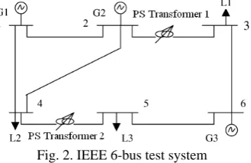
In order to show the effect of flowgate bidding and dispatchable transmission service in security constraint unit commitment on cost reduction, enhancement reliability and contingencies management, a case study based on the 6-bus system and the IEEE 24-bus Reliability Test System are presented in this section. a) Six bus test system
Six bus system (shown in Fig. 2) has three units, seven transmission lines and two phase-shifting transformers. The phase-shifting transformers are considered as FACTS device which is a dispatchable service and can offer price for shifts of flow by the phase-shifting mechanism. Data and information about the 6-bus system are available from Ref [15, 18]. Load for 6 h of scheduling period SCUC&DTS is shown in Table 1.
Fig. 2. IEEE 6-bus test system
Table 1. Load for 6 h of scheduling period energy and reserve market
Time Load (MW) SR (MW) OR (MW)
1 180 2.70 12.60 2 190 2.85 13.30 3 200 3.00 14.00 4 240 3.60 16.80 5 248 3.70 17.15 6 246 3.60 16.65
44
Table 2. Offer prices for quantity the transmission element exceeds its steady state operating level in contingencies
Block flowgate bidding based on percentage of steady state rating
5 % 10% 15%
Offer price for each block 40 ($/MWh) 80 ($/MWh) 120 ($/MWh)
Table 3. Offer price for FACTS device
Offered shifts of flow by the phase-shifting transformers
5 MW 10 MW 15 MW
Offer price for shifts of flow 10 ($/MWh) 15 ($/MWh) 20 ($/MWh)
The following cases are considered: Case 1: Base case SCUC without DTS Case 2: DTS is considered in Case 1
Case 3: Outage of line 2–4 is considered in Case 2 Case 4: Outage of unit 2 is considered in Case 2
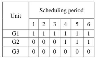
In the case 1, we apply the UC schedule with incorporate dc load flow constraints. In this case, the commitment schedule is shown in Table 4.
Table 4. The unit commitment schedule without DTS
Unit
Scheduling period
1 2 3 4 5 6
G1 1 1 1 1 1 1 G2 0 0 0 1 1 1 G3 0 0 0 1 0 0
Because of the load incrassation in time period 4, unit 2, 3 are turned on to help mitigate violations and supply the load. Cost of operation in this case is 34754 $.
Now DTS is considered in case 1. Information of DTS is shown in Tables 2, 3. By running the program in this case, offers from the phase-shifting transformer in line 4-5 in which line 4-5 in time period 4, 5, 6 was congested, is accepted for shifting flow. In this condition, the phase-shifting transformer in line 4-5 is switched on instead of turning on unit 3 and in time period 5, 6 leads to a higher dispatch of unit 1. Therefore operating cost in this case was reduced because of using the phase-shifting transformer in line 4-5. In this case, the commitment schedule is shown in Table 5. Cost of operation in this case is 34004 $.
Table 5. The unit commitment schedule with DTS
Unit Scheduling period
1 2 3 4 5 6
G1 1 1 1 1 1 1
G2 0 0 0 1 1 1
G3 0 0 0 0 0 0
In case 4 outage of unit 2 is considered, therefore unit 1 cannot satisfy the hourly load. Unit 3 is committed additionally to supply the load without DTS.
By considering DTS, in time period 3, the phase-shifting transformer in line 4-5 and line 2-3 are switched on. Therefore unit 3 in time period 3 is not committed. Operation cost in this case and case without DTS in case 4 is 34916 $ and 35002 $, respectively.
In cases studied on 6 bus test system, the possible savings in operation cost using DTS can be found. The DTS in SCUC lead to using cheaper units for operation and mitigating transmission flow violations in lines.
b) IEEE 24-bus reliability test system
IEEE 24-bus Reliability Test System (IEEE RTS) has three phase shifting transformers. In order to show the effect of the DTS, the capacity of all branches is decreased by 30%. The phase-shifting transformers installed in lines 11-9, 11-10 and 11-13 are considered as FACTS device which is a dispatchable service and can offer price for shifts of flow by the phase-shifting mechanism. The offer prices for the quantity the transmission element exceeds its steady state operating level in contingencies is show in Table 2 and offer price for FACTS device as dispatchable transmission service is available in Table 3.
In this case, we apply the UC schedule with incorporate dc load flow constraints. The total operating cost without DTS is 598752 $. DTS solution results are presented in Table 6.
Table 6. DTS solution results
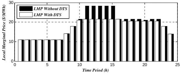
Total cost saving percent is 4.8 %. Thus, in Table 6, the operating cost in row 2 is smaller than that of row 1. Also, LMPs are reduced at system buses. Fig. 3 depicts the LMP at bus 1 for the two cases over the 24-h 24-horizon. It can be seen from Fig. 3 t24-hat compared to wit24-hout DTS, LMPs are reduced in DTS in peak hours.
0 5 10 15 20 25
0 10 20 30
Time Peiod (h)
L
o
c
a
l Ma
rg
in
al P
ric
e
(
$
/MW
h
)
LMP Without DTS LMP With DTS
Fig. 3. Effect of DTS in LMP at bus 1
In peak hours 11-15 in which load is at high level, the phase-shifting transformer in line 11-9, 11-10 and 11-13 are switched on.
Total operating cost without DTS 578852 $
Total operating cost with DTS 551067 $
DTS cost 5325 $
46
4. CONCLUSION
In this paper an attempt is made to produce a comprehensive modeling of dispatchable transmission lines, and in particular, apply flowgate bidding or incremental transmission capacity and dispatchable transmission service in a well-known engineering test case to gain a better understanding of its potential impact in large systems.
Dispatchable Transmission Service and Flowgate Biddings in Security Constraint Unit Commitment introduced here can provide the market with greater efficiency and competition. Dispatchable Transmission Service and Flowgate Biddings in Security Constraint Unit Commitment do not exist today; however, these results are informative to show that this is a topic worthy of further research based on the possible savings. In this paper it was shown that Dispatchable Transmission Service and Flowgate Biddings could be part of the smart grid concept aims at making better use of the current infrastructure as well as additions to the grid that enable more sophisticated use of the network. DTS adds flexibility to the optimization problem and may allow for better generation dispatch solutions. The overall cost of the network, which includes this additional DTS cost, would be lower overall, thereby creating a net savings. DTS solution results showed the reduction in operation cost as well as LMP in buses.
NOMENCLATURE
i index of generating units
s index of segments of piecewise linear cost function of generating units
k index of lines which represent the quantity the transmission element exceeds its steady state operating level
m index of mth step flowgate bidding function of the line k which represents the quantity the transmission element exceeds its steady state operating level
j index of lines in which the Phase-Shifting transformers and FACTS devices were installed
p index of pth segment of capacity Phase-Shifting transformer and FACTS device which were installed in line j
t index of time horizon b index of bus
c index of contingency
l index of total transmission lines NG number of generating units
Nk number of lines representing the quantity the transmission element exceeds its steady state operating level
Nm number of steps in the flowgate bidding function of the line k representing the quantity the transmission element exceeds its steady state operating level
NJ number of lines in which the Phase-Shifting transformers and FACTS devices are installed Np number of segment in capacity Phase-Shifting transformer and FACTS device which was installed
in line j
NT number of scheduling hours
NS number of segments of piecewise linear cost function of generating unit Nb number of total buses
Ub number of generating units connected to bus b Lb number of lines connected to bus b
NC number of contingency
Nl number of total transmission lines
i
t
s
,
offered energy cost segment s of unit i in time t
i
t
P
s,
power generation of unit i in segment s at time t
i
SUC
start up cost unit i
i
t
SUC
,
start up cost unit i in time t
i
i tSDC , shutdown cost unit i in time t
iPs,max upper limit of real generation of unit i in segment s
i
t
P
,
real power generation of unit i at time t
iPmin minimum production of unit i
i
,
t
commitment state of unit i at time t
iPmax maximum production of unit i
on i
T minimum up time of unit i
off i
T minimum down time of unit i
on t i
X , on time of unit at time t
off t i
X , off time of unit at time t
i
t
R
S,
spinning reserve of unit i in time t
i
t
R
O,
operating reserve of unit i in time t
t
R
S system spinning reserve requirement in time t
t
R
O operating spinning reserve requirement in time t
i
UR
ramp up rate limit of unit i
i
DR
ramp down rate limit of unit i
b
t
PD
,
load demand of bus b at time t
jt xpDevice
FACTS , situation of the pth segment of capacity Phase-Shifting transformer and FACTS device which
were installed in line j at time t
jtPFACTSDeviceAddCap,p , the pth segment capacity for line j equipped with Phase-Shifting transformer and FACTS devices
j
t
PL
,
transmission flow in lines with Phase-Shifting transformers and FACTS devices was installed jt Cost
Cha
Adj FACTSDevice , reservation cost for changing power shift at time t in Phase-Shifting transformers and FACTS
. devices in line j
ACC
reservation cost for changing power shift in Phase-Shifting transformers and FACTS devices
k t PFBm servation ,max ,
Re
maximum reservation capacity of the mth segment of capacity the kth transmission line element
..exceeds its steady state operating level
k
P
..percent of the steady-state operating level of transmission element k
k tStatem , ..statement of the reservation capacity of the mth segment of capacity the kth transmission line
..element exceeds its steady state operating level
k tPFBmUsage , ..usageable capacity of the mth segment of capacity the kth transmission line element exceeds its
..steady state operating level
k tPFBUsage , ..usageable capacity of the kth transmission line element exceeds its steady state operating level
k tPL , ..transmission flow in of the kth transmission line element exceeds its steady state operating level
b tBPM1 , ..surplus slack variables for power mismatch at bus b at time t
b tBPM2 , ..deficit slack variables for power mismatch at bus b at time t
t
V
..power mismatch at time t
i
,
t
..marginal change in violations with increase in unit generation at time t
m
,
t
..phase angle of bus m at time t
i tIc , ..the contingency state of unit i at time t in contingency c
i t48
t c
V ..power mismatch at time t in contingency c
l tc n ,
..phase angle of bus m at time t in contingency cl
x
..reactance of line lMPC(i) ..minimum production cost for unit i
REFERENCES
1. Aflaki, K, Jadid, S. & Shahidehpour, M. (2009). Electricity restructuring in Iran: Achievements and challenges.
ELSEVIER,The Electricity Journal, Vol. 22, No.2, pp. 74~83.
2. Azami, R., Aflaki, K. & Haghifam, V. (2010). A demand response based solution for LMP management in power markets. International Journal of Electrical Power & Energy Systems, doi: 10.1016/j.ijepes.2010.12.018 3. Koglin, H. J. & Muller, H. (1980). Overload reduction through corrective switching actions. Proc. IEE
International Conf. on Power System Monitoring and control, London, pp. 159-164.
4. Rolim, J. G. & Machado, L. (1999). A study of the use of corrective switching in transmission systems. IEEE Trans. on Power Systems, Vol. 14, No. 1, pp. 336-341.
5. Makram, E. B., Thornton, K. P. & Brown, H. E. (1989). Selection of lines to be switched to eliminate overload lines using a Z-matrix method. IEEE Trans. on Power Systems, Vol. 4, No. 2, pp. 653-661.
6. Glavitsch, H. (1985). State of the art review- switching as means of control in the power system. International Journal of Electrical Power and Energy Systems, Vol. 7, No. 2, pp. 92-100.
7. Bacher, R. & Glavitsch, H. (1986). Network topology optimization with security constraints. IEEE Trans. on Power Systems, Vol. 1, No. 4, pp. 103-111.
8. Schnyder, G. & Glavitsch, H. (1987). Integrated security control using an optimal power flow and switching concepts. Proc. IEEE Power Industry Computer Application Conf., Montreal, Canada, May, pp. 429-435. 9. Schnyder, G. & Glavitsch, H. (1990). Security enhancement using an optimal switching power flow. IEEE
Trans. on Power Systems, Vol. 5, No. 2, May, pp. 674-681.
10. O’Neill, R. P., Baldick, R., Helman, U., Rothkopf, M. H. & Stewart, W. (2005). Dispatchable transmission in RTO markets. IEEE Trans. Power Syst., Vol. 20, No. 1, pp. 171–179.
11. Fisher, E. B., O’Neill, R. P. & Ferris, M. C. (2008). Optimal transmission switching. IEEE Trans. Power Syst., Vol. 23, No. 3, pp. 1364–1355.
12. Hedman, K. W., O’Neill, R. P., Fisher, E. B. & Oren, S. S. (2008). Optimal transmission switching—sensitivity analysis and extensions. IEEE Trans. Power Syst., Vol. 23, No. 3, pp. 1469–1479.
13. Hedman, K. W., O’Neill, R. P., Fisher, E. B. & Oren, S. S. (2009). Optimal transmission switching with contingency analysis. IEEE Trans. Power Syst., Vol. 24, No. 3, pp. 1577–1586.
14. Hedman, K. W., O’Neill, R. P., Fisher, E. B. & Oren, S. S. (2010). Co-optimization of generation unit commitment and transmission switching with N-1 reliability. IEEE Trans. Power Syst., Vol. 25, No. 2, pp. 1052–1063.
15. Khodaei, A. & Shahidehpour, M. (2010). Transmission switching in security-constrained unit commitment.
IEEE Trans. Power Syst., Vol. 25, No. 4, pp. 1937–1945.
16. Hedman, K. W., O’Neill, R. P. & Fisher, E. B. & Oren, S. S. (2011). Smart felixble just in time transmission and flowgate bidding. IEEE Trans. Power Syst., Vol. 26, No. 1, pp. 93–102.
17. Shivaie, M., Sepasian, M. S. & Sheikh–El–Eslami, M. K. (2011). Multi-objective transmission expansion planning using fuzzy-genetic algorithm. IJST, Transactions of Electrical Engineering, Vol. 35, No. E2, pp 141– 159.
19. Soroudi, A. R. & Ehsan, M. (2010). Multi-objective planning model for integration of distributed generations in deregulated power systems. IJST, Transactions of Electrical Engineering, Vol. 34, No. 3, pp 307-324.
20. Wu, L., Shahidehpour, M. & Li, T. (2007). Stochastic security-constrained unit commitment. IEEE Trans. Power Syst., Vol. 22, No. 2, pp. 800–811.
21. Fu, Y., Shahidehpour, M. & Li, Z. (2005). Security-constrained unit commitment with AC constraints. IEEE Trans. Power Syst., Vol. 20, No. 3, pp. 1538–1550.
22. Shahidehpour, M. & Fu, Y. (2005). Benders decomposition. IEEE Power and Energy Mag., Vol. 3, No. 2, pp. 20–21.