Vol. 2, No. 1, pp. 7-16, Jan (2019)
Improvement of Direct Power Control of DG-Interfaced Grid
Connected Power Converter
Ehsan Talebian Kouchaksaraei
*, and Mehrdad Ahmadi Kamarposhti
†**In this study a new technique of Direct Power Control (DPC) is proposed to connect distributed generation sources to the nationwide grid. This technique not only adds power of distributed generation sources to the grid, but also is capable to compensate the reactive and harmonic power of non-linear loads as well. In this study, converters’ voltage references for generating compensation current are directly calculated in synchronous rotating coordinate system in each period of sampling; then, a proper pulse width modulation (PWM) generates the used voltages. The proposed DPC technique has some advantages including simple algorithm of fast dynamic as well as fixed switching frequency and small sampling frequency. The performance of the proposed direct control technique is confirmed by simulation results.
Article Info
Keywords:
Active and Reactive Power; Renewable Energy Sources; Interface Grid-Connected Converters; Harmonic Distortion; Parallel Active Filter.
Article History:
Received 2018-03-13
Accepted 2018-06-25
I.
I
NTRODUCTIONLimitation of fossil fuel reserves and environmental pollution resulting from their use, especially in cities, as well as low efficiency of current energy converters lead to the tendency towards the use of more efficient energy converters and renewable energy sources. The use of distributed generation (DG) is one of the appropriate solutions in this regard. There are various techniques provided to control these converters. Although this technique is able to achieve common goals such as active and reactive power control and sinusoidal current waveforms, it has different concepts. Especially, voltage-oriented control (VOC) that guarantees appropriate dynamic and static behavior because its internal current control loops are highly taken into consideration. Unfortunately, the efficiency of VOC is highly dependent on the quality of the strategy used for current controllers [1].
Another technique which is being paid more attention these days is Direct Power Control (DPC) that has features such as simple structure and high dynamic response as well as lack of dependence on the parameters of the system.
This technique can be implemented in several forms that the first and the simplest technique among others is the switching- based technique [2]. Despite enjoying numerous advantages, direct power control technique based on the switching table, sampling frequency must be chosen very large to achieve good performance, which itself leads to large switching frequency of a variable that has made it difficult to design filter, and, the filter also increases losses [2-7].
Due to the different production capacity of distributed generation sources as well as different frequency of production with city electric, the scenario of connecting distributed generation sources to power grid creates different challenges [1].
On the other hand, due to non-linear and reactive loads in power systems and the incidence of harmonic distortion, we need to devise techniques to remove or reduce the harmonic effects on the power system; hence, Active Power Filter (APF) is a proper technique to name. Installing DG systems costs a lot; therefore, we can combine and install APF performance with systems of distributed generation sources with the
A B S T R A C T
†
Corresponding Author : [email protected], [email protected]
*
Department of Electrical Engineering, Sari Branch, Islamic Azad University, Sari, Iran
†** Department of Electrical Engineering, Jouybar Branch, Islamic Azad
purpose of decreasing the cost and increasing productivity. According to what have been mentioned, there is a need to evaluate the simultaneous performance of the converter as interface converter as well as improving power quality or active filter. In DPC not only the need to PI controllers and hysteresis is obviated, but also have it provided proper steady state and dynamic behavior (due to error in steady state and speed response). Switching frequency is also steady in this technique and the sampling frequency values are small. There is no dependence on the system parameters in this technique. On the other hand, this technique does not have hard and complicated calculations like predictive techniques, which needs an objective function and the optimization of this objective function [8]. Controlling voltages in synchronous rotating machine are obtained using the values of variables and system parameters and very simple mathematical operations like addition, multiplication, and division.
The PI controller has been widely used as current controller in variety of inverter applications because of its simplicity and stability. The design and implementation of this controller are quite straightforward in continuous as well as in discrete-time domain [9]. Furthermore, low computational burden of this control algorithm makes it easier to implement the whole control system with only one digital signal controller. However, despite these advantages, the PI controllers have the limitation that they are unable to cope with sinusoidal reference signals and periodic disturbances [10]. Although the sinusoidal tracking problem can be completely solved by implementing the controller in the synchronously rotating reference frame, poor disturbance rejection capability makes the PI type controller unsuitable for current control strategy of a grid-connected inverter in the presence of the distorted grid voltages.
For the purpose of eradicating the harmonics from inverter currents, several control approaches have been proposed, which is categorized as selective and non-selective methods [11]. Proportional resonant (PR) controller is widely used as selective harmonic compensation scheme [12]. This controller is often implemented in the stationary reference frame and the resonant term is added to the main controller to suppress the harmonic component in the specific order. However, since this method requires separate resonant terms to compensate each harmonic component, this approach is usually considered to alleviate only a few harmful low order harmonics. When the numbers of resonant terms increase, the control structure becomes complicated or even impractical. Other approaches to eliminate the harmonics from inverter current use nonlinear control techniques such as the sliding mode control (SMC) [13], predictive control [14], or repetitive control [15].
These control strategies are often referred as non-selective method since the controllers work in wide range of frequency, in contrast to the selective method that only regulates the
harmonics in some specified orders. By using such nonlinear controllers, the distorted level of inverter current can be mitigated even under the distorted grid voltages. However, the design task of a robust controller based on above techniques usually makes the system structure complicated because of the remaining problems related to those techniques such as the chattering problem in SMC, parameter sensitive in predictive control, slow dynamic response in repetitive control and so on. Furthermore, the practical complexity of nonlinear controller may degrade the performance of the controlled system.
As another approach, a neural-network-based waveform processing and filtering scheme has been reported to reshape voltage or current waveforms [16].
However, this algorithm generally requires lots of computations to be processed in real time, which increases the computational burden of main controller. Moreover, offline training is often required in this method. Recently, a sliding mode harmonic compensation strategy based on the system model decomposition has been reported to reduce the harmful effects caused by the nonlinear controller [17]. In this work, the system model is first divided into two using the fundamental and harmonic components. Using two decomposed models, the controllers are separately designed, that is, the controller for the fundamental term by the conventional decoupling controller and the harmonic suppression controller by SMC. To decompose the grid voltages and inverter currents into the fundamental and harmonic components, the fourth-order band pass filters (BPFs) have been employed in the harmonic extractors. As reported in [17], even though the steady-state current responses can be quite improved with reduced chattering by adopting the decomposed model, the inverter system exhibits a slow transient response due to the sluggish dynamic characteristics of the BPF. Moreover, the slow response of the BPF may even cause the instability problem during transient duration.
In addition to current controller, the phase lock loop (PLL) also influences on the inverter currents under the distorted grid voltages. Indeed, the conventional synchronous reference frame phase lock loop (SRF-PLL) algorithm integrated with a PI controller to determine the angular displacement of grid voltage is unable to cope with high frequency disturbances due to the limitation of the PI controller.
voltages [18,19]. The main concept of the MAF-PLL is to use the MAF as an ideal low pass filter (LPF) to remove the sinusoidal components in the synchronous reference frame before the measured grid voltages are processed in PLL algorithm.
In this paper, direct control of the components d and q of the converter voltage, based on the reference and measured values of the power, the measured voltage of the AC source and the system parameters, can be controlled entirely by active and reactive power. Voltage reference values, produced by a voltage modulator, generate PWM gate-gate signals.
This paper is organized as follows: Section 2 presents the principles of controlling the proposed direct control technique. Section 3 describes the the formula of proposed direct power control technique. Simulation results are presented in Section 4. Finally, the conclusions are given in Section 5.
II.
P
RINCIPLES OF CONTROLLING THE PROPOSEDDIRECT CONTROL TECHNIQUE
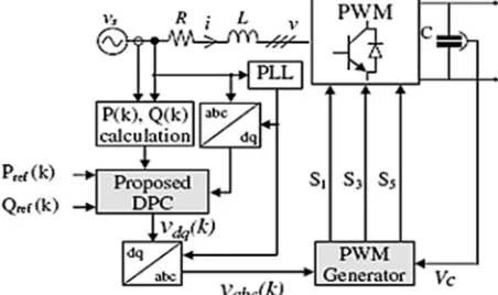
As can be seen from figure1 (The structure of grid-connected convertor), interface converters and active filter are quite similar in terms of the power circuit. This is just the performance of controller and the way to determine the reference values that confirm the differences between performance of interface converter and active filter.
In case that the purpose of control is the output value of active and reactive power, synchronous can be acquired and applied based on the values of reference powers in the reference system. According to the fact that voltage reference values are in the synchronous machine, these values must be
first transferred to abc and/or α-β static machine (based on a
selected modulator) and then switching signal is produced using a suitable modulator. In this paper, a modulator is selected to produce switching signal based on SVM technique. [20, 21]
In case that a three-phase converter, as a grid-connected three-phase converter, is being used to add power of DG to the grid, reference powers for converter must be determined through DG. In most cases, the converter works at unity power factor, and in special cases, the converter is used to generate active power.
As stated above, active filter has the duty to compensate harmonic components and reactive load. Therefore, based on
p-q theory, rate in the active and reactive powers relate to the
harmonic components of loads. Then, it can be maintained that sinusoidal and free of harmonics in grid current can be achieved with this rate of compensation.
Compensation of all the reactive power is assumed in this study in order to unite the power factor in the grid. According to the proposed technique, the active and reactive reference power value must be determined to control a grid-connected
three-phase converter. Then, according to the above mentioned cases, it can be concluded that reference values are like equations 1 and 2 [22, 23].
= (1) = - (2) In which and are oscillating active and reactive power
related to non-linear load and is the fixed reactive power of
non-linear load that is drawn from the grid.
In order to generate the current reference, a balance between instantaneous power supplied by the source and the
active filter and drained by the load is to be computed. If ps and
qs are the real and imaginary instantaneous powers supplied by
the main while pf and qf are the real and imaginary
instantaneous power supplied by the active power filter, in order to compensate reactive power and eliminate harmonic
currents, the main should supply = and = 0. The
oscillatory component of plis to be fed by APF, while ql must
be fully fed by the APF because in this way it is possible to
achieve power compensation too. The oscillatory part of pl is
due to harmonic components, so if it is fed to the load by the active filter, source current remains sinusoidal, while the load keeps on receiving the same amount of harmonic and fundamental current. Power balance yields:
= ; = 0 = − = + − =
(3)
= − = (4)
Previous Eqs. (3) and (4) need to be modified in order to consider proper operation of the capacitor on the DC side of the inverter. The capacitor stores energy which is utilised as a power supply for the normal operation of the active filter. More in ideal, in normal operating condition APF does not
feed active power because it should be able to supply =
, = and so only reactive power. For this reason,
capacitor voltage level is constant during the steady state and varies during transients.
A control of voltage value is needed to regulate voltage level in the steady state and to limit the variability of voltage during transients and during start up. So, the calculation of current reference wave should consider the need to move power balance in order to charge or discharge the DC side capacitor of the active filter. In order to regulate DC voltage level is necessary to control active power balance among source, load and APF. When the load absorbs a precise
quantity of power and if > , power in excess is drawn
by the APF, which increases DC side voltage. If < ,
since the load needs a precise amount of power, the APF feeds
the remaining part in order to have + = and so DC
Fig. 1.The structure of grid-connected converter
Reactive power Qref (k) set to zero for unity power factor
and active power Pref (k) delivered from the outer
integral-proportional (IP) DC voltage controller.
III.
A
CHIEVING THE FORMULA OF PROPOSEDDIRECT POWER CONTROL TECHNIQUE
According to Figure1, formula (5) is right:
a a sa a
b b sb b
c c sc c
i i v v
d
L i R i v v
dt
i i v v
= − + − (5)
In (5), V stands for voltage converters vector, Vs stands for
source voltage vector AC, L and R are resistance and
inductance equivalent between the source and converter. It must be mentioned that in these converters the mutual inductance is always ignored, or sometimes according to the feature of balanced three-phase, the effective inductance of each phase that includes interaction as well, is counted.
Park’s transform is used for transferring to the stationary reference frame. According to the relation between static reference frame and synchronous rotating frame, the equations 6 and 7 that is called as Clarke is used for direct transferring from three-phase reference frame to synchronous rotating
frame with synchronous speed w (frame dq).
j t d q
xrα β = xr e ω (6)
( )
( )
2 2
cos cos cos
3 3
2
3 2 2
sin sin sin
3 3 a d b q c x
t t t
x
x x
t t t x
π π
ω ω ω
π π
ω ω ω
− + = − − − − + (7)
According to the equations 6 and 7, for transferring from static reference frame to synchronous rotating frame with
synchronous speed (ω), equation 5 changes to 8, where
ω
isangular frequency of voltage source.
1
1
(
)
dq dq sdq dq
d
R
i
j i
v
v
dt
= − −
L
ω
+
L
−
L
uur
uur
uuur
uur
(8)
Now the desired model must be broken. To do this, equation 8 is used to derive current in each small sampling
period (Tsp).
(
1)
( )
dq dq
dq
sp
d
i
k
i
k
i
dt
T
+ −
=
r
r
uur
(9)By replacing equation 9 into 8 and with component analysis
of d and q, the following equations will be resulted:
( 1) ( ) ( ) sp( ( ) ( )) ( ) dq sp dq sdq dq dq
T R
i k T j i k v k v k i k
L
ω
L+ =− + + − +
r r r r r
(10)
( 1) (1 ) ( ) ( ) ( ( ) ( ))
( 1) (1 ) ( ) ( ) ( ( ) ( ))
sp sp
d d sp q sd d
sp sp
q q sp q sq q
T T
i k i k T i k v k v k
L L
T T
i k i k T i k v k v k
L L ω ω + = − + + − + = − − + − (11)
On the other hand, relations of instantaneous active and reactive powers in synchronous rotating reference frame based
on p-q theory are as follow:
(
1)
(
1) (
1)
(
1) (
1)
(
1)
(
1) (
1)
(
1) (
1)
sd d sq q
sq d sd q
P k
v k
i k
v k
i k
Q k
v k
i k
v k
i k
+ =
+
+ +
+
+
+ =
+
+ −
+
+
(12)It can be ignored with a good approximation of changes in voltage source in each sampling period, which means:
(
1)
( )
(
1)
( )
sd sd
sq sq
v
k
v
k
v
k
v
k
+
≅
+
≅
(13)Using the above-mentioned equations and then sorting them, we will have:
2 2
( 1) (1 ) ( ) ( ) ( ( ) ( ) ( ) ( ) ( ) ( ) ( 1) (1 ) ( ) ( ) ( ( ) ( ) ( ) ( ))
sp sp
sp sd sq sd d sq q
sp sp
sp sd q sq d
T R T
Pk Pk T Qk v k v k v k v k v k v k
L L
T R T
Qk Qk T Pk v k v k v k v k
L L ω ω + = − − + + − − + = − + + − (14)
Now we assume that the purpose of the control system is in the next period of sampling the instantaneous values of active and reactive powers should be equal with the reference values:
( 1) ( )
( 1) ( ) ref
ref
P k P k Q k Q k
+ =
+ = (15)
By replacing the two equations of 13 and 15 in the 14th
equation, the required values for converter voltage in reference
frame dq will be obtained that materializes the 15th equation,
which itself is the prerequisite of control:
2 2 2 2 ( ) ( ) ( ) ( ) ( ) ( ) ( ) ( ) ( ) ( ) ( ) ( ) ( ) ( ) ( ) ( ) ( ) ( ) ( ) sd sq d sd
sp sd sq
sd ref sq ref sq sd sp sd sq
v k P k v k Q k L
v k v k R
T v k v k
v k P k v k Q k v k P k v k Q k L
L
T v k v k
ω
2 2
2 2 2 2
( ) ( ) ( ) ( ) ( ) ( ) ( ) ( ) ( ) ( ) ( ) ( ) ( ) ( ) ( ) ( ) ( ) ( ) ( ) ( ) ( ) sq sd q sq
sp sd sq
sq ref sd ref sd sq
sp sd sq sd sq
v k P k v k Q k L
v k v k R
T v k v k
v k P k v k Q k v k P k v k Q k L
L
T v k v k ω v k v k
− = + − + − + − − + + (17)
Now we want to reduce the size of the equations 16 and 17, thanks to the use of PLL the control system is synchronized
with the AC voltage source vector, therefore, the q component
of voltage source is zero in the control equations (v ksq( ) 0= ).
Hence, the simplified form of the 16th and 17th will be 18th and
19th:
( ) ( ) ( ) ( ) ( ) ( ) ( ) ( ) ( ) ref d sd
sp sd sp sd sd
P k
L P k L Q k
v k v k R L
T v k T v k ωv k
= + − − − (18)
( ) ( ) ( ) ( ) ( ) ( ) ( ) ( ) ref q
sp sd sp sd sd
Q k
L Q k L P k
v k R L
T v k T v k ωv k
= − − + − (19)
The equations 18 and 19 are the final equations of the proposed direct control power that will be used from now on. Just as it was considered, by following a process not so complex and quite logical, we have achieved a simple equation to calculate directly the converter’s voltage reference values.
IV.
R
ESULTS OFS
IMULATIONSTo evaluate the direct power control technique that its equations and relations were obtained in the previous part, and according to the figure1 the structure of one-linear grid-connected converter, some simulation have been done in MATLAB and SIMULINK. These simulations include three general parts. In the first part, the performance of control system is evaluated just as interface converter of DG. Next, the control system is discussed and evaluated in the active filter condition. Finally, the simultaneous performance of DG interface converter and active filter will be presented as well. These simulations include the evaluation of the behavior of the system’s steady state and system’s dynamic state in response to stepwise changes. DG is considered as a constant voltage source in these simulations. In fact, the dynamic system of energy generation through DG is ignored. In general, it can be mentioned that the DG link did not have a particular dynamic; therefore, it was somehow considered as ideal. To this end, the parameters of the simulated system are presented in table1 below:
Table1: Parameters of the simulated system
1 mH Converter inductance Laf
1 mΩ
Converter resistance Raf
0.1 mH Grid inductance Lg
71 Vpeak
Source phase voltage
s v
50 Hz Source voltage Frequency fs
150 V DC bus Voltage Vdc
A. Evaluate the performance of the control system in the interface converter
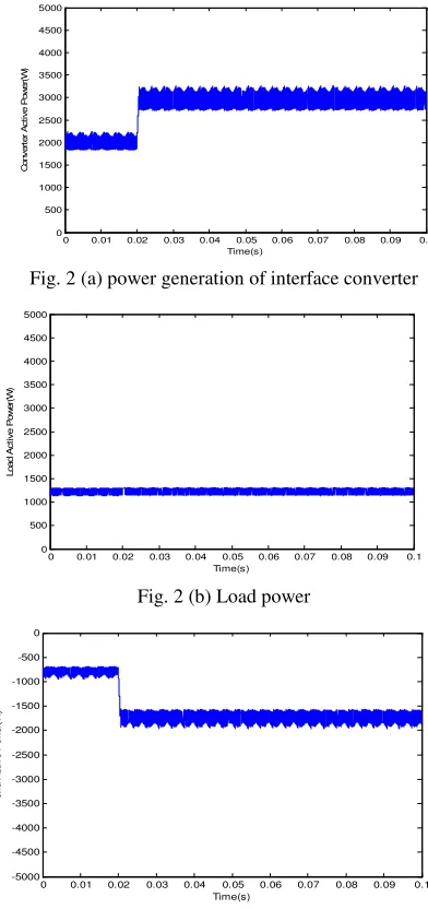
According to figure 2, in a steady state the amount of power generated by interface converter is set as 2000 watts. In order to evaluate the performance of the dynamic state of control system a stepwise change in the amount of 1000 watts in 0.02 seconds is given to the reference power generation rate (through interface convertor). As it is obvious, the control system followed the reference value in short of 5ms and adjusted the values of active and reactive powers in reference values. In this situation, the required load power is about 1300 watts; therefore, a portion of the power converter is added to the load and the rest to the grid that the power generation of the grid, in this case, is negative. In fact, the load power and power injected into the grid are equal with generating power of interface converter.
Fig. 2 (a) power generation of interface converter
Fig. 2 (b) Load power
Fig. 2 (c) Active power drawn from the grid
0 0.01 0.02 0.03 0.04 0.05 0.06 0.07 0.08 0.09 0.1 0 500 1000 1500 2000 2500 3000 3500 4000 4500 5000 Time(s) C o n v e rt e r A c ti v e P o w e r( W )
0 0.01 0.02 0.03 0.04 0.05 0.06 0.07 0.08 0.09 0.1 0 500 1000 1500 2000 2500 3000 3500 4000 4500 5000 Time(s) L o a d A c ti v e P o w e r( W )
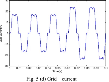
Fig. 2 (d) Grid current
Fig. 2. (a) power generation of interface converter, (b) Load power, (c) Active power drawn from the grid
(d) Grid current
B. Evaluate the performance of the control system in the state of active filter
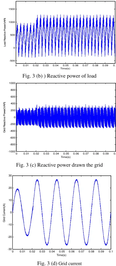
Figure 3 presents the evaluation of the control system’s performance in the state of active filter. A non-linear load in a steady state (three-phase Diode Bridge) is located at the outlet. This load draws a non-sinusoidal current along with pulsations of active and reactive powers from the grid that this pulsation will be removed through the performance of active filter. In order to evaluate the dynamic performance of the proposed direct power control technique a stepwise increase change to the amount of 40% is set in the load at the time of 0.06 seconds. It is worth mentioning that the power generation of DG is considered zero at this state. As can be seen from figure 3, the reactive power starts working in the state of complete compensation that means the whole power of reactive load is compensated through active filter. One of the standards of power quality is the total harmonic distortion (THD) that represents the harmonic amount of the desired signal. According to table 2, the amount of THD in load current is 20.08%, which is taken from the grid. This amount then after the compensation of active filter reached at 1.9%, which means that the active filter had its best performance in compensating the harmonic components of load current, which could meet the international standards.
Fig. 3 (a) Reactive power generation of APF
Fig. 3 (b) ) Reactive power of load
Fig. 3 (c) Reactive power drawn the grid
Fig. 3 (d) Grid current
Fig. 3. (a) Reactive power generation of APF, (b) Reactive power of load, (c) Reactive power drawn the grid (d) Grid current
C. The simultaneous performance of interface converter and active filter
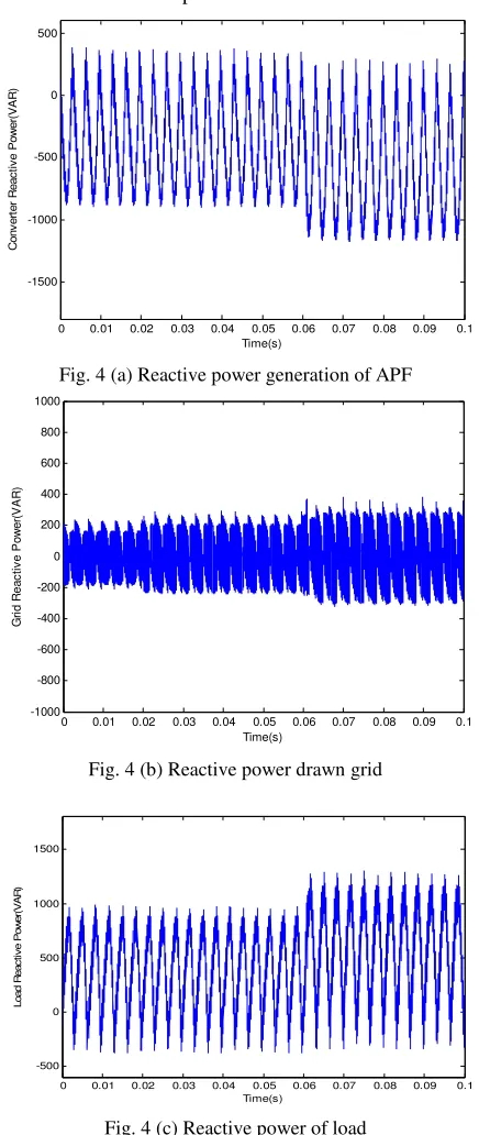
According to figures 4 and 5, in the steady state the injection power of interface convertor is set on 400 watts. The convertor will also act in state of compensating the harmonic components and reactive power. Two changes happen due to the act of dynamic state of the control system when interface convertor and active filter are working simultaneously. In the first change, one level of decrease happened in the 400-watt power in the power generation amount of interface convertor at the time of 0.02 seconds. In the next change, an increase of 40% happened in the amount of non-linear load at the time 0.06 seconds. As can be seen from figure4, the convertor has
0 0.01 0.02 0.03 0.04 0.05 0.06 0.07 0.08 0.09 0.1 -30
-20 -10 0 10 20 30
Time(s)
C
o
n
v
e
rt
e
r
C
u
rr
e
n
t(
A
)
0 0.01 0.02 0.03 0.04 0.05 0.06 0.07 0.08 0.09 0.1 -1500
-1000 -500 0 500
Time(s)
C
o
n
v
e
rt
e
r
R
e
a
c
ti
v
e
P
o
w
e
r(
V
A
R
)
0 0.01 0.02 0.03 0.04 0.05 0.06 0.07 0.08 0.09 0.1 -500
0 500 1000 1500
Time(s)
L
o
a
d
R
e
a
c
ti
v
e
P
o
w
e
r(
V
A
R
)
0 0.01 0.02 0.03 0.04 0.05 0.06 0.07 0.08 0.09 0.1 -1000
-800 -600 -400 -200 0 200 400 600 800 1000
Time(s)
G
ri
d
R
e
a
c
ti
v
e
P
o
w
e
r(
V
A
R
)
0 0.01 0.02 0.03 0.04 0.05 0.06 0.07 0.08 0.09 0.1 -30
-20 -10 0 10 20 30
Time(s)
G
ri
d
C
u
rr
e
n
t(
A
done well in the compensation process of reactive power of the load, and pulsation of the active and reactive load power is compensated by active filter. According to figure4, the reactive power drawn from the grid is also zero, which represents the proper performance of active filter. From the figure5, it can be seen that the average load power is provided through power generation of interface convertor and the average power taken from the grid. The THD of grid current amount in a simultaneous performance after compensation are shown in table 2 and figure 6, which represents a proper performance of the active power.
Fig. 4 (a) Reactive power generation of APF
Fig. 4 (b) Reactive power drawn grid
Fig. 4 (c) Reactive power of load
Fig. 4 (d) Interface converter current
Fig. 4. (a) Reactive power generation of APF, (b) Reactive power drawn grid, (c) Reactive power of load (d) Interface
converter current
Fig. 5 (a) Power generation of interface converter
Fig. 5 (b) Active power drawn the grid
Fig. 5 (c) ) Load power
0 0.01 0.02 0.03 0.04 0.05 0.06 0.07 0.08 0.09 0.1 -1500 -1000 -500 0 500 Time(s) C o n v e rt e r R e a c ti v e P o w e r( V A R )
0 0.01 0.02 0.03 0.04 0.05 0.06 0.07 0.08 0.09 0.1 -1000 -800 -600 -400 -200 0 200 400 600 800 1000 Time(s) G ri d R e a c ti v e P o w e r( V A R )
0 0.01 0.02 0.03 0.04 0.05 0.06 0.07 0.08 0.09 0.1 -500 0 500 1000 1500 Time(s) L o a d R e a c ti v e P o w e r( V A R )
0 0.01 0.02 0.03 0.04 0.05 0.06 0.07 0.08 0.09 0.1 -30 -20 -10 0 10 20 30 Time(s) C o n v e rt e r C u rr e n t( A )
0 0.01 0.02 0.03 0.04 0.05 0.06 0.07 0.08 0.09 0.1 -1000 -500 0 500 1000 1500 time(s) c o n v e rt e r a c ti v e p o w e r
0 0.01 0.02 0.03 0.04 0.05 0.06 0.07 0.08 0.09 0.1 1000 1200 1400 1600 1800 2000 2200 2400 2600 2800 3000 Time(s) G ri d A c ti v e P o w e r( W )
Fig. 5 (d) Grid current
Fig. 5. (a) Power generation of interface converter, (b) Active power drawn the grid, (c) Load power (d) Grid current Table 2: Comparing different state of convertor performance from
view of power quality indicator THD
THD Grid Current Amount
Different State of Convertor Performance
20.08 without Interface Convertor’s Performance 2.59 Performance in the State of Active Filter
3.63 Simultaneous Performance of Interface Convertor and Active Filter
Fig. 6 (a) Without Interface Convertor’s Performance
Fig. 6(b) Performance in the state of active filter
Fig. 6 (c) Simultaneous Performance of Interface Convertor and Active Filter
Fig. 6. Comparing different state of convertor performance from view of power quality indicator THD
V.
C
ONCLUSIONUsing voltage source converters is increasing sharply, and one of the reasons for that is the increase in using new energies like solar energy, wind turbine, etc. Nonetheless, these convertors still have their traditional uses like active filters. Various techniques have been introduced to control these kinds of convertors. Although these techniques are capable to achieve common goals like active and reactive control and sinusoidal current waveform, they have different concepts. On the other hand, unlike predictive technique, which needs an objective function and optimizing this objective function, this proposed technique does not have complex and heavy calculations. Controlling voltages in synchronous rotating machine are obtained using the values of variables and system parameters and very simple mathematical operations like addition, multiplication, and division. On the other hand, in addition to transferring power, the interface convertor should also take part in compensating harmonics and components of active power load (active filter). Therefore, the speed response of control system to current changes should be fast and dynamic. All simulations done confirm the proper operation of controllers both in steady and dynamic state.
R
EFERENCE[1] P. Acuna, L. Moran, M. Rivera, J. Dixon, J. Rodriguez.," Improved Active Power Filter Performance for Renewable Power Generation Systems" IEEE TRANS ON Power Electronics, vol. 29, no. 2, FEBRUARY 2014.
[2] M. Jasinsk, D. Swierczynski, and M. P. Kazmierkowski, “Novel sensorless direct power And torque control of space vector modulated AC/DC/AC converter,” IEEEISIE, pp.1147-1152.in Proc.2004
[3] J. Restrepo, J. M. Aller, J. Viola, and A. Bueno, “Optimum space vector computation technique for direct power control,” IEEE Trans. Power Electron., vol. 24, no. 6,pp. 1637-1645June 2009.
0 0.01 0.02 0.03 0.04 0.05 0.06 0.07 0.08 0.09 0.1 -30
-20 -10 0 10 20 30
Time(s)
L
o
a
d
C
u
rr
e
n
t(
A
[4] S. A. Larrinaga, M. A. R. Vidal, E. Oyarbide, and J. R. T. Apraiz, “Predictive control strategy for DC/AC converters based on direct power control.” IEEE Trans. Ind. Electron., vol. 54, no.3, pp. 1261-1271, June 2007.
[5] M. Cichowlas, M. Malinowski, F. Blaabjerg, “Direct power control for three-phase PWM Rectifier with active filtering function,” IEEE ISIE, in proc,2003.
[6] L. liming, L. Hui, x. Yaosuo and L. wengsin, "Decoupled Active and Reactive Power Control for Large-Scale Grid-Connected Photovoltaic SystemsUsing Cascaded Modular Multilevel Converters." IEEE Trans. On power Electronics vol. 30 , NO. 1, January 2015.
[7] J. Restrepo, J. Viola, J. M. Aller, and A. Bueno, “A Simple switch selection state for SVM direct power control,” IEEE ISIE, pp. 1112-116., in Proc, 2006.
[8] J. Rodriguez, J. Pontt, C. A. Silva, P. Correa, P. Lezana, P.Cortes, and U. Ammann, “predictive Current control of a voltage source inverter,” IEEE Trans. Ind. Electron., vol. 54, no. I, pp495-503, Feb. 2007.
[9] Bouzid, A.M.; Guerrero, J.M.; Cheriti, A.; Bouhamida, M.; Sicard, P.; Benghanem, M. A survey on control of electric power distributed generation systems for microgrid applications. Renew. Sustain. Energy Rev. 2015, 44, 751– 766.
[10]Teodorescu, R.; Liserre, M.; Rodríguez, P. Grid Converters
for Photovoltaic and Wind Power Systems, 1st ed.; John Wiley and Sons: West Sussex, UK, 2011; pp. 313–321. [11]Blaabjerg, F.; Teodorescu, R.; Liserre, M.; Timbus, A.V.
Overview of control and grid synchronization for distributed power generation systems. IEEE Trans. Indus. Electr. 2006, 53, 1398–1409.
[12]Teodorescu, R.; Blaabjerg, F.; Liserre, M.; Loh, P.C. Proportional-resonant controllers and filters for grid-connected voltage-source converters. IEE Proc. Electr. Power Appl. 2006, 153, 750–762.
[13]Hu, J.; Shang, L.; He, Y.; Zhu, Z.Q. Direct active and reactive power regulation of grid-connected dc/ac converters using sliding mode control approach. IEEE Trans. Power Electr. 2011, 26, 210–222.
[14]Fischer, R.J.; González, S.A.; Carugati, I.; Herrán, M.A.; Judewicz, M.G.; Carrica, D.O. Robust predictive control of grid-tied converters based on direct power control. IEEE Trans. Power Electr. 2013, 29, 5634–5643.
[15]Chen, D.; Zhang, J.; Zhang, Z. An improved repetitive control scheme for grid-connected inverter with frequency-adaptive capability. IEEE Trans. Ind. Electr. 2013, 60, 814–823.
[16]Zhao, J.; Bose, B.K. Neural-network-based waveform processing and delayless filtering in power electronics and AC drives. IEEE Trans. Ind. Electr. 2004, 51, 981–991. [17]Kang, S.W.; Kim, K.H. Sliding mode harmonic
compensation strategy for power quality improvement of a grid-connected inverter under the distorted grid condition. IET Power Electr. 2015, 8, 1461–1472.
[18]Golestan, S.; Ramezani, M.; Guerrero, J.M.; Freijedo, F.D.; Monfared, M. Moving average filter based phase-locked loops: Performance analysis and design guidelines. IEEE Trans. Power Electr. 2014, 29, 2750–2763.
[19]Golestan, S.; Guerrero, J.M.; Abusorrah, A.M. MAF-PLL with phase-lead compensator. IEEE Trans. Ind. Electr. 2015, 62, 3691–3695.
[20]J. Restrepo, J. Viola, J. M. Aller, and A. Bueno, “A Simple switch selection state for SVM direct power control,” IEEE ISIE, pp. 1112-116., in Proc.,2006.
[21]J. Restrepo, J. M. Aller, J. Viola, and A. Bueno, “A simplified rectifier voltage vector selectionfor direct power control,” IEEEICCDCS,pp. 1-5. in Proc, 2008.
[22]A. Chaoui, J. paul gaubert and F.karim " Power quality improvement using DPC controlled three-phase shunt active filter", Elsevier, Electric Power Systems Research 80, 2009. [23] M. Malinowski, M. P.Kazmierkowski , S. Hansen, F Blaabjerg, and G. D Marques, “Virtual flux based direct power control of three-phase PWM rectifiers,”IEEE Trans, Ind. Applicat,. Vol. 37, pp. 1019-1027, Guly/Aug. 2001.
Ehsan Talebian Kouchaksaraei was born in Qaemshahr, Mazandaran, Iran. He received the M.S. degree in power electrical engineering from Science and Research Branch, Islamic Azad University, Sari, Iran, in 2015. His research interests are Power Quality, Micro grid, renewable energy, optimization algorithm, power electronic.
IECO