Please cite this article as: M. Rezaiee-Pajand, A. Aftabi Sani, S. M. Hozhabrossadati, Free Vibration of a Generalized Plane Frame,International Journal of Engineering (IJE),IJE TRANSACTIONS A: Basics Vol. 31, No. 4, (April 2018) 538-547
International Journal of Engineering
J o u r n a l H o m e p a g e : w w w . i j e . i rFree Vibration of a Generalized Plane Frame
M. Rezaiee-Pajand*, A. Aftabi Sani, S. M. Hozhabrossadati
Department of Civil Engineering, Ferdowsi University of Mashhad, Mashhad, Iran
P A P E R I N F O
Paper history: Received 05 October 2017
Received in revised form 30 November 2018 Accepted 01 December 2017
Keywords:
Differential Transform Method Free Vibration
Plane Frames
Elastic Supports and Joints
A B S T R A C T
This article deals with the free in-plane vibration analysis of a frame with four arbitrary inclined members by differential transform method. Based on four differential equations and sixteen boundary and compatibility conditions, the related structural eigenvalue problem will be analytically formulated. The frequency parameters and mode shapes of the frame will be calculated for various values of the structural properties, such as joint angles, springs' stiffness and flexural rigidity of members. Finally, the obtained solution by the proposed method will be verified by authors' finite element program.
doi: 10.5829/ije.2018.31.04a.04
1. INTRODUCTION1
Frames are important structural systems, which are widely used in civil, mechanical and electrical engineering [1]. Due to vast applications, the problem of vibrating frames has been extensively studied by researchers, so far. For instance, Filipich and Laura [1] dealt with the analysis of in-plane vibrations of the portal frames with end supports, which were elastically restrained against rotation and translation. Kounadis and Meskouris [2] studied the vibration of a rigid-jointed triangular frame, in which its joint mass was eccentrically located with respect to its theoretical position. In another study, Filipich et al. [3]determined the fundamental frequency of vibration of a frame elastically restrained against translation and rotation at the ends, carrying concentrated masses by using the Rayleigh-Ritz method. Filipich et al. [4] dealt with the analysis of the first symmetric mode of vibration of a generally restrained frame with non-prismatic members carrying concentrated masses.
It is interesting to mention that Chang and Chang [5] studied free and forced out-of-plane vibrations of elastic plane frames. The structural torsional effect of the out-of-plane vibration was examined in their investigation.
*Corresponding Author Email: rezaiee@um.ac.ir (M. Rezaiee-Pajand)
In a comparison of the frequencies of in and out-of-plane vibrations, it was revealed that the basic frequency of a plane frame corresponds to an out-of-plane vibration mode. Lee [6] presented natural frequencies and mode shapes for the in-plane vibration of a triangular closed frame by employing Rayleigh-Ritz method. Later, the natural frequencies and mode shapes of various frame structures were calculated by Lee and Ng [7]. In order to describe each member of the frame and the necessary continuity conditions due to the axial rigidity, they employed Rayleigh-Ritz technique and a different set of admissible functions. Their proposed scheme was illustrated for a portal frame, an H-frame and a T-frame.
of planar serial-frame structures. A hybrid analytical/ numerical scheme was proposed that permitted the efficient evaluation of the problem eigen solutions. Some natural frequencies and mode shapes were also found. Heppler et al. [12] examined the dynamics of a two-member open frame undergoing both in- and out-of-plane motion.
Mei [13] obtained a solution for the in-plane vibration problem of planar structures. Furthermore, Kaveh and Alizadeh Arvanaq [14] proposed a numerical method for the free vibration analysis of symmetric planar frames. More recently, Rezaiee-Pajand and Khajavi [15] presented a finite element formulation for the vibration analysis of plane frames. The strain gradient notation was utilized to determine the mass and stiffness matrices. Both Euler-Bernoulli- and Timoshenko- beam elements were investigated in their study. Sakar et al. [16] studied the free vibration and dynamic stability of multi-span frames by finite element method. In another event, Mei [17] used a wave vibration approach to analyze the free vibration of single-story multi-bay planar frame structures. Moreover, Yucel et al. [18] dealt with the coupled axial- flexural- torsional vibration of the Timoshenko frames. Ratazzi et al. [19] investigated the in-plane free vibration of an L-shaped frame with an internal hinge. The system was clamped at one end and elastically restrained at the other. Failla [20] presented the exact solution for frequency response analysis of Euler-Bernoulli beams and plane frames with an arbitrary number of Kelvin-Voigt viscoelastic dampers. Typical external and internal dampers were considered, as grounded translational, tuned mass, rotational and translational dampers for bending and axial vibrations. The frequency response functions were obtained using generalized functions and Green's functions. Rezaiee-Pajand et al., [21] dealt with the free vibration of a gabled frame with rotational springs. Moreover, Rezaiee-Pajand et al., [22]studied free vibration of a space frame coupled with a six-degree-of-freedom mass-spring.
It is worth mentioning that there are only limited numbers of the solutions available on the frames free vibration analyses, which have elastically restrained ends and joints [23-25]. Grossi and Albarracin [25] took advantage of the calculus of variations to derive a more interestingly boundary value problem. They studied the dynamical behavior of two- and three-bar frames with inclined members, which the structural ends and intermediate joints were elastically restrained. Four issues were covered in their study. First, a brief description of textbooks and papers previously published was presented. Second, the variational formulation of the problem was given. Third, Hamilton's principle was rigorously stated, and the corresponding eigenvalue problem was obtained.
Finally, the separation of variables was utilized for determination of the exact frequencies and mode shapes. It is well known that there are two basic tactics accessible for analyzing the dynamical systems; the equilibrium scheme and the energy technique. For implementing the equilibrium approach, only the knowledge of statics and Newton's law of motion are required. In fact, it is a very straightforward and simple strategy for the researchers. On the other hand, the energy way is based on the calculus of variations, which may not be as easy as the previous technique for all investigators. However, due to the numerical nature, the use of the energy scheme may be advantageous in some problems.
According to the presented brief review, a lot of researches have been so far conducted on the free vibration of different frames. Due to immense applications, there will be more study on this subject in the coming future. To authors' best knowledge, the free vibration of a frame with four inclined members and elastic restraints has not been yet treated. Therefore, the main aim of this article is to fill this gap via two different methods, namely, differential transform
method (DTM) and finite element approach.
Differential transform method is a semi-analytical approach which takes advantage of Taylor's series in the solution process. Simplicity, high accuracy, computational stability and rapid convergence could be considered as main properties of DTM.
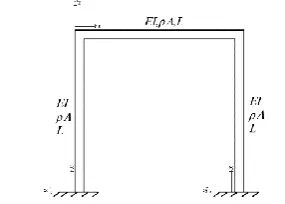
In this article, the free vibration of a generalized frame is investigated. The studies frame has four inclined member. Moreover, the model's generality is increased by imposing fifteen springs. The studied model is plotted in Figure 1. The equilibrium approach will be employed to obtain the eigenvalue problem, by including four differential equations and sixteen boundary and compatibility conditions. Furthermore, authors' finite element program will be utilized to verify the outcomes. It should be mentioned that the effect of axial deformation is not considered in the analysis. This assumption is valid for most frames. However, for frames with low moment of inertia and low slenderness ratios, the effect of axial deformation may be appreciable [26, 27].
2. GOVERNING DIFFERENTIAL EQUATIONS
For the generalized frame of Figure 1, the following differential equation of motion, governing the free bending vibration of each slender uniform member according to Euler-Bernoulli beam theory, can be written [28]:
4 4
4 0 1, 2,3, 4
i i i d u
u i
In the last relationship, u x ti( , ) is the function of the transverse deformation of the ith member, and i is the frequency parameter of the ith beam, which can be defined as:
2 4
1, 2,3, 4
i i i i i A i E I
(2)
In this equation, E Ii i, i and Ai indicate the flexural stiffness, density and cross-sectional area of the ith beam, respectively. Besides,
is the circular frequency of the frame. It has the next relationship with i:2
1, 2,3, 4
i i i i i E I i A
(3)
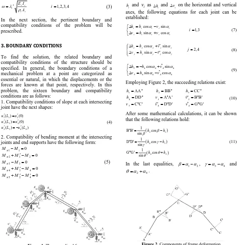
In the next section, the pertinent boundary and compatibility conditions of the problem will be prescribed.
3. BOUNDARY CONDITIONS
To find the solution, the related boundary and compatibility conditions of the structure should be specified. In general, the boundary conditions of a mechanical problem at a point are categorized as essential or natural, in which the displacements or the forces are known at that point, respectively. In this problem, the sixteen boundary and compatibility conditions are as follows:
1. Compatibility conditions of slope at each intersecting joint have the next shapes:
1 1 2
3 3 4
2 2 4 4
( ) (0)
( ) (0)
( ) ( )
u L u
u L u
u L u L
(4)
2. Compatibility of bending moment at the intersecting joints and end supports have the following form:
1 1
2 1 2
3 3
4 3 4
5 2 4
0 0 0 0 0 R R R R R M M
M M M
M M
M M M
M M M
(5)
Figure 1. The generalized frame
The subsequent notations are utilized:
5 5 2 2
(0) ( )
(0) ( )
i i i i
i i i i i
Ri Ri i
R R
M E I u
M E I u L
M K u
M K u L
(6)
with i1, 2,3, 4.
It should be added that the remaining eight conditions are more complicated. Therefore, great emphasis is required for finding them. Each joint has two degrees of freedom, i.e.,
h
i andv
i. By defining the projections ofi
h and
v
i as hi and vi on the horizontal and vertical axes, the following equations for each joint can be established:cos sin
1,3 sin cos
i i i i i
i i i i i
h h v
i
v h v
(7) cos sin 2, 4 sin cos
j j j j j
j j j j j
h h v
j
v h v
(8)
5 4 4 4 4
5 4 4 4 4
ˆ cos sin
ˆ sin cos
h h v
v h v
(9)
Employing Figure 2, the succeeding relations exist:
1 2 3
4 1 2
3 4 4
AA '' BB'' CC ''
DD '' A''A ' B''B' ˆ C''C ' D''D ' G'''G '
h h h
h v v
v v v
(10)
After some mathematical calculations, it can be shown that the following relations hold:
2 1 4 3 4 2 1 B''B' cos sin 1 D''D' cos sin 1
G'''G ' cos
sin h h h h h h (11)
In the last equalities, 1 2, 3 4 and
2 4
.
In order to find h1h4, the next equations are written
for the functions
u
1
u
4:1(0) 1
u v (12a)
1 1 2 1
1
( ) cos
sin
u L h h
(12b)
2 2 1
1
(0) cos
sin
u h h
(12c)
2 2 4 2
1
( ) cos
sin
u L h h
(12d)
3(0) 3
u v (12e)
3 3 4 3
1
( ) cos
sin
u L h h
(12f)
4 4 3
1
(0) cos
sin
u h h
(12g)
4 4 2 4
1
( ) cos
sin
u L h h
(12h)
Solving Equations (12b) and (12c) for
h
1 andh
2,equations (12d) and (12h) for
h
2 andh
4 and Equations(12f) and (12g) for
h
3 andh
4, will give the coming results:2 1 1
1
(0) ( ) cos sin
u u L
h
(13)
2 1 1
2
(0) cos ( ) sin
u u L
h
(14)
4 4 2
2
( ) (0) cos
sin
u L u
h
(15)
2 2 4 4 4
( ) ( ) cos sin
u L u L
h
(16)
4 3 3
3
(0) ( ) cos sin
u u L
h
(17)
4 3 3
4
(0) cos ( ) sin
u u L
h
(18)
Equating the two expressions, obtained for h2 and h4, yields two conditions:
2(0) cos 1( 1) 4( 4) 2(0) cos
sin sin
u u L u L u
(19)
4 3 3
2( 2) 4( 4) cos (0) cos ( )
sin sin
u u L
u L u L
(20)
In order to find the remaining six conditions, the equilibrium of shear and axial forces in each member, as well as two end supports, should be considered. As it is shown in Figure 3, the shear forces are denoted by Vi and the axial forces are indicated by
i
N . Moreover, springs' forces are denoted by FHi and FVi.
The equilibrium of shear and axial forces at the left support gives the following relationships:
1 1 1 1 1
1 1 1 1 1
cos sin 0
sin cos 0
H
V
N V F
N V F
(21)
where
1 1 1
1 1 1
H H
V V
F K h
F K v
(22)
Solving Equation (21) for N1 and
1
V gives the next
equalities:
1 H1 1cos 1 V1 1sin 1
N K h K v (23)
and
1 H1 1sin 1 V1 1cos 1
V K h K v (24)
On the other hand, using the definition of the shear will lead to V1E I u1 1 1(0). The two values obtained for V1 must be equal. Therefore, the eleventh condition has the subsequent appearance:
1 1sin 1 1 1cos 1 1 1 1(0)
H V
K h K v E I u (25)
Similarly, for the other end, the following relations hold:
3 3sin 3 1 1cos 3 3 3 3(0)
H V
K h K v E I u (26)
and
3 H3 3cos 3 V3 3sin 3
N K h K v (27)
Equation (26) is also a condition. At this stage, the equilibrium of shear and axial forces at the intersecting joints is considered.
As a result, the succeeding systems of equations for nodes 2 and 4 are found:
2 2 2 2 1 1 1 1 2
2 2 2 2 1 1 1 1 2
cos sin cos sin 0
sin cos sin cos 0
H
V
N V N V F
N V N V F
(28)
4 4 4 4 3 3 3 3 4
4 4 4 4 3 3 3 3 4
cos sin cos sin 0
sin cos sin cos 0
H
V
N V N V F
N V N V F
(29) in which
i i i i
N N m h (30)
or
2 i i i i i i
N N A L h (31)
and
2 2 2
2 2 2
4 4 4
4 4 4
1 1 1 1 1
3 3 3 3 3
( ) ( ) H H V V H H V V
F K h
F K v
F K h
F K v
V E I u L V E I u L
(32)
Solving Equations (27) and (28), for N2, V2, N4 and
4
V
, and substituting the values of V2E I u2 2 2(0) and4 4 4 4(0)
V E I u , give the thirteenth and fourteenth conditions as follows:
2 2 2 1 1 2 1 2
1 1 2 1 2
2 2 2 2 2 2
(0) cos sin sin cos
sin sin cos cos
sin cos
H V
E I u N
V
K h K v
(33)
4 4 4 3 3 4 3 4
3 3 4 3 4
4 4 4 4 4 4
(0) cos sin sin cos
sin sin cos cos
sin cos
H V
E I u N
V
K h K v
(34)
Finally, the equilibrium of shear and axial forces at joint 5 results in the fifteenth and sixteenth conditions:
2 2 2 2 4 4 4 4 5
2 2 2 2 4 4 4 4 5
cos sin cos sin 0
sin cos sin cos 0
H
V
N V N V F
N V N V F
(35) where
5 5 5
5 5 5
2 2 2 2 2
4 4 4 4 4
( )
( )
H H
V V
F K h
F K v
V E I u L
V E I u L
(36)
It is interesting to note that all the forces in Equation (35) are known. In fact, these two equations are similar to two conditions. Therefore, the sixteen boundary and compatibility conditions of the problem are found. It may be useful to summarize all of these conditions in the following lines, once again.
4. SOLUTION BY DIFFERENTIAL TRANSFORM
By definition, the differential transform of function
( )
f x around point
x
0 is given by [21, 29]:0
1 ( ) ( )
!
k
k x x d f x F k
k d x
(37)
in which the original function is demonstrated by ( )f x , and the transformed one is denoted by F k( ). The inverse transform is defined as:
0 0
( ) ( )k ( )
k
f x x x F k
(38)Combining Equations (37) and (38) results in:
0 0 0 ( ) ( ) ( ) ! k k k
k x x
x x d f x f x
k d x
(39)Equation (39) may be written as:
0 0 0 ( ) ( ) ( ) ! k k N k
k x x
x x d f x
f x
k d x
(40)where N is selected such that the natural frequencies of the system converge.
Next, the differential transform should be applied on the governing differential equations and boundary and compatibility conditions of the problem. It is customary to nondimensionalize the differential equations and
boundary conditions for implementing DTM.
Introducing i x L/ i , Equation (1) becomes [21]:
4 4
4 0 1, 2,3, 4
i i i i
d u
u i
d (41)
in which
i is the dimensionless frequency parameter of each member:2 4 4
1, 2,3, 4
i i i
i i i A L i E I
(42)
Furthermore, the boundary and compatibility conditions take new shapes by using the introduction of i x L/ i . Applying the differential transform on Equation (41), the differential transformed form of the governing differential equations is found as:
4
( ) ( 4)
( 1)( 2)( 3)( 4)
i i i
U K
U k
k k k k
(43)
Substituting U ki( ) into these transformed boundary and compatibility conditions leads to a system of algebraic equations. Setting the determinant of the coefficient matrix equal to zero gives the frequency equation of the frame. Finally, solving the resulting frequency equation yields the natural frequencies of the generalized frame under study.
In another way, a finite element model for the system is constructed. According to the numerical experiences, the results found by the finite element method are in excellent agreement with the values obtained by DTM. This is a clear confirmation for the accuracy of authors' formulations.
5. NUMERICAL RESULTS
The frequency parameters and mode shapes of the frame are calculated for different values of the structural parameters in this section. The dimensionless frequency parameters of the structure, i.e., 1 1L, corresponding to each mode will be shown in the related figure.
Example 1
As a first example, the portal frame with clamped (c-c) ends and simply-supported (ss-ss) ends are considered. Figure 4 shows this structure with clamped ends. The below properties of the frame are utilized:
4 4 3 3 2 2 1 1
4 4 3 3 2 2 1 1
4 3 2 1
1 2 3 4
1 1 3 3
2 2 2 4 4 4 5 5 5
1 3
1 3
90, 0, 90, 0
0 clamped ends
0 simply-supported ends
H V H V
R H V R H V R H V
R R
R R
E I E I E I E I
A A A A
L L L L
K K K K
K K K K K K K K K
K K
K K
(44)
Table 1 presents the first four dimensionless frequency parameters of the frames by DTM and FEM. Moreover, the results proposed by Filipich and Laura [1] are given in this table. Comparing the proposed values by DTM and FEM with Filipich and Laura [1] shows the accuracy of the solutions. The rapid convergence of DTM is observed.
Furthermore, Table 1 suggests that decreasing the
Figure 4. The structure under study in example 1
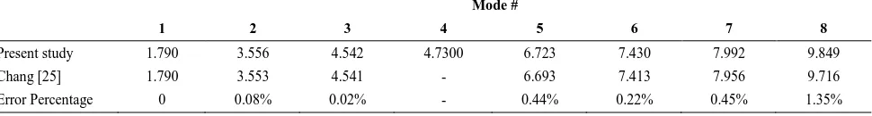
stiffness of the end rotational springs, i.e., KR1 and KR3, from infinity to zero, which are associated to clamped ends and simply- supported ends, the dimensionless frequency parameters decrease. This is due to a decrease in stiffness of the structure. It is informative to point out that the natural frequencies of many frames, including portal frame are available in Chang [25]. This work considered the axial deformation. He showed that the axial deformation can be neglected. It is worthwhile to compare the natural frequencies of a portal frame with clamped ends obtained in this article and proposed by the present authors. Table 2 shows the first eight
s. The slender ratio of all members, i.e., 2(AL / )I i, is considered equal to 100 in Chang [25]. From Table 2, it is evident that axial deformation can be surely neglected. It is observed that maximum error percentage occurs in the eighth mode. This is just 1.45% which can be definitely neglected in frame analysis. It should be mentioned that for frame members with a slender ratio greater than 40, which happens for most frame structures, the axial deformation can be neglected. It is interesting to mention that two famous methods, which are widely used for frame analyses, are moment distribution, and slope deflection schemes. Both lead to the exact solutions, while neglecting shear and axial deformations. This is because they are the minor structural effects. It is worth mentioning that the fourth mode is missing in Chang [25].
To investigate the versatile portal frame further, a more complicated portal frame is analyzed. It is assumed that the symmetric spring conditions exist, i.e.,
1 2 3 4 1
H H H H
K K K K T
,
KV1KV2KV3KV4T2and1 2 3 4
R R R R
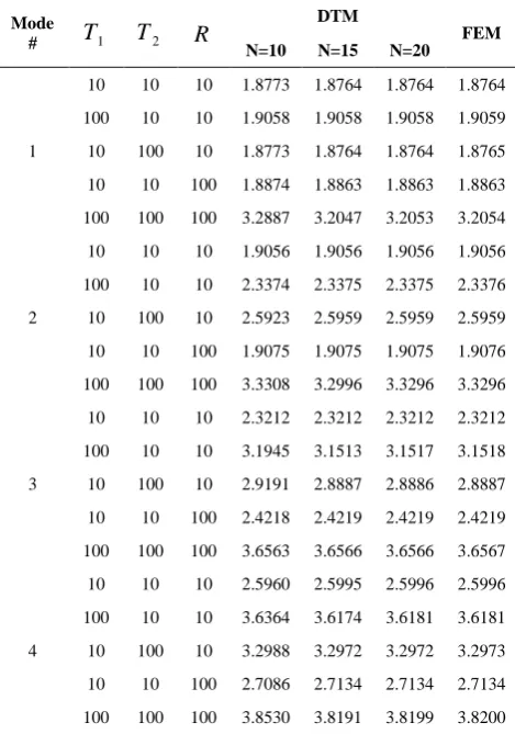
K K K K R.The values of the first four dimensionless frequency parameters obtained by DTM and FEM are inserted in Table 3 for various amounts of
1
T , T2 and
R
. This table clearly indicates the fast convergence of DTM for this example. Furthermore, this table is advantageous for analyzing the effect of horizontal, vertical and rotational springs on the natural frequencies of the frame. From Table 3, it is observed that increasing the stiffness of horizontal springs, i.e., T1 , has the most influence on dimensionless frequency parameters; nextR
and then T2. On the other hand, for the second mode, this order is T2, T1 andR
. Finally, in the higher modes, i.e., the third and fourth modes, T1 is more influential. In these modes, T2 has more effect on natural frequencies thanR
. Generally speaking, these outcomes clearly indicate that the natural frequencies of the frame are most sensitive to horizontal springs. On the contrary, the rotational springs have less effect on the natural frequencies of the portal frame. Figure 5 demonstrates the first four mode shapes of the frame for1 2 100
TABLE 1.The values of the first four dimensionless frequency parameters for portal frames with clamped and simply-supported ends
support Mode # DTM FEM [1]
N=10 N=15 N=20 NE=16 NE=32 NE=64
c-c
1 1.7941 1.7901 1.7901 1.7901 1.7901 1.7902 1.7901
2 3.6804 3.5555 3.5563 3.5566 3.5563 3.5563 3.5564
3 4.5547 4.5418 4.5838 3.5418 4.5418 4.5419
4 4.7168 4.7301 4.7322 4.7302 4.7301
ss-ss
1 1.2095 1.2095 1.2095 1.2095 1.2095 1.2095 1.2095
2 3.1196 3.1413 3.1415 3.1417 3.1415 3.1416 3.1416
3 3.8565 3.8542 3.8551 3.8543 3.8543 3.8543
4 4.2979 4.2976 4.2984 4.2977 4.2975
TABLE 2. The values of the first eight dimensionless frequency parameters for portal frames with clamped ends Mode #
1 2 3 4 5 6 7 8
Present study 1.790 3.556 4.542 4.7300 6.723 7.430 7.992 9.849
Chang [25] 1.790 3.553 4.541 - 6.693 7.413 7.956 9.716
Error Percentage 0 0.08% 0.02% - 0.44% 0.22% 0.45% 1.35%
Figure 5. The first four frequency parameters and mode shapes of frame studied in example 1
Example 2
This example is devoted to a gabled frame with clamped ends and simply-supported ends. The properties of the frame can be expressed as:
4 4 3 3 2 2 1 1
4 4 3 3 2 2 1 1
4 2 3 1
1 2 3 4
1 1 3 3
2 2 2 4 4 4 5 5 5
1 3
1 3
2 2
90, 30, 90, 30
0 clamped ends
0 simply-supported ends
H V H V
R H V R H V R H V
R R
R R
E I E I E I E I A A A A L L L L
K K K K
K K K K K K K K K K K
K K
(45)
Presented in Table 4 are the first four dimensionless frequency parameters of the studied system with the clamped ends and simply-supported ends. Once again, it can be seen from Table 4 that the values of the gabled frame with simply-supported ends are smaller than those of the gabled frame with clamped ends. Furthermore, this difference is more considerable in the fundamental mode.
Example 3
A two-member frame with clamped ends will be studied in this section. The properties of the system have the next appearance:
(46)
4 4 3 3 2 2 1 1
4 4 3 3 2 2 1 1
4 3 2 1
1 2 3 4
1 1 1 3 3 3
2 2 2 4 4 4 5 5 5
30
0
R H V R H V
R H V R H V R H V
E I E I E I E I
A A A A
L L L L
K K K K K K
K K K K K K K K K
TABLE 3. The values of the first four dimensionless frequency parameters for portal frames with different amounts of
T
1,T
2 andR
Mode
#
T
1T
2R
DTM
FEM N=10 N=15 N=20
1
10 10 10 1.8773 1.8764 1.8764 1.8764
100 10 10 1.9058 1.9058 1.9058 1.9059
10 100 10 1.8773 1.8764 1.8764 1.8765
10 10 100 1.8874 1.8863 1.8863 1.8863
100 100 100 3.2887 3.2047 3.2053 3.2054
2
10 10 10 1.9056 1.9056 1.9056 1.9056
100 10 10 2.3374 2.3375 2.3375 2.3376
10 100 10 2.5923 2.5959 2.5959 2.5959
10 10 100 1.9075 1.9075 1.9075 1.9076
100 100 100 3.3308 3.2996 3.3296 3.3296
3
10 10 10 2.3212 2.3212 2.3212 2.3212
100 10 10 3.1945 3.1513 3.1517 3.1518
10 100 10 2.9191 2.8887 2.8886 2.8887
10 10 100 2.4218 2.4219 2.4219 2.4219
100 100 100 3.6563 3.6566 3.6566 3.6567
4
10 10 10 2.5960 2.5995 2.5996 2.5996
100 10 10 3.6364 3.6174 3.6181 3.6181
10 100 10 3.2988 3.2972 3.2972 3.2973
10 10 100 2.7086 2.7134 2.7134 2.7134
100 100 100 3.8530 3.8191 3.8199 3.8200
TABLE 4. The values of the first four dimensionless frequency parameters for a gabled frame with clamped and simply-supported ends
support Mode 1 Mode 2 Mode 3 Mode 4 c-c 1.14374 1.49562 2.03554 2.22608
ss-ss 0.77266 1.26502 1.90396 2.2129
Figure 6 presents the first four mode shapes of the frame. In order to investigate the effect of flexural rigidity of members, this frame with a far stiffer member than the other is considered. The properties of the system for this case are as follows:
4 4 1 1 3 3 1 1 2 2 1 1
4 4 1 1 3 3 1 1 2 2 1 1
4 3 2 1
1 2 3 4
1 1 1 3 3 3
2 2 2 4 4 4 5 5 5
/ 10000, / 10000, / 1
/ 100, / 100, / 1
30, 30, 30, 30
0
R H V R H V
R H V R H V R H V
E I E I E I E I E I E I
A A A A A A
L L L L
K K K K K K
K K K K K K K K K
(47)
The first four mode shapes of the frame are plotted in Figure 7.
Figure 6. The first four frequency parameters and mode shapes of frame studied in example 3 with properties expressed in Equation (46)
It is clear that the stiffer member is just excited in the third mode, which may be due to the high stiffness of the member.
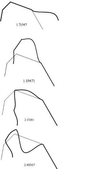
Example 4
In this example, a general frame with un-symmetric geometry is studied. The properties of the frame are given in the following equations:
(48)
The first four mode shapes of the system are plotted in Figure 8.
Figure 8. The first four frequency parameters and mode shapes of frame studied in example 4
6. CONCLUSIONS
The aim of this paper was to derive the frequency parameters and mode shapes of a generally restrained frame with four inclined members by using DTM. The intersecting joints of the system were also elastically
restrained against rotation, horizontal and vertical translations. The frequency parameters and mode shapes were calculated for a wide range of the structural parameters, such as joint angles, springs' stiffness, length and flexural stiffness of the members. In order to verify the values obtained by the precise formulation, a finite element program was developed by the authors. All numerical experiences clearly demonstrated that the values found by the FEM method were very close to those of obtained by DTM. These actions confirmed that the suggested formulations were all accurate. In addition to the mention issues, the free vibration of the portal frame was also investigated, as a special case.
7. REFERENCES
1. Filipich, C. and Laura, P., "In-plane vibrations of portal frames with end supports elastically restrained against rotation and translation", Journal of Sound Vibration, Vol. 117, (1987), 467-473.
2. Kounadis, A. and Meskouris, K., "The coupling effect of axial motion and joint mass on the lateral vibrations of a rigid‐jointed triangular frame", Earthquake Engineering & Structural Dynamics, Vol. 15, No. 4, (1987), 447-461.
3. Laura, P., De Greco, B.V. and Filipich, C., "In-plane vibrations of frames carrying concentrated masses", Journal of Sound and Vibration, Vol. 117, No. 3, (1987), 447-458.
4. Filipich, C., de Greco, B.V. and Laura, P., "A note on the analysis of symmetric mode of vibrations of portal frames",
Journal of Sound and Vibration, Vol. 117, No. 1, (1987), 198-201.
5. Chang, G.-S. and Chang, C.-H., "Out-of-plane vibrations of plane frames", Journal of Sound and Vibration, Vol. 147, No. 1, (1991), 137-154.
6. Lee, H., Natural frequencies and modes for the in-plane vibration of a triangular closed frame. 1993, Academic Press.
7. Lee, H. and Ng, T., In-plane vibration of planar frame structures. 1994, Academic Press.
8. Aktas, E. and Moses, F., "Reduced basis eigenvalue solutions for damaged structures∗", Journal of Structural Mechanics, Vol. 26, No. 1, (1998), 63-79.
9. Oguamanam, D., Hansen, J. and Heppler, G., "Vibration of arbitrarily oriented two-member open frames with tip mass",
Journal of Sound and Vibration, Vol. 209, No. 4, (1998), 651-669.
10. Sophianopoulos, D., "The effect of joint flexibility on the free elastic vibration characteristics of steel plane frames", Journal of Constructional Steel Research, Vol. 59, No. 8, (2003), 995-1008.
11. Lin, H. and Ro, J., "Vibration analysis of planar serial-frame structures", Journal of Sound and Vibration, Vol. 262, No. 5, (2003), 1113-1131.
12. Heppler, G., Oguamanam, D. and Hansen, J., "Vibration of a two-member open frame", Journal of Sound and Vibration, Vol. 263, No. 2, (2003), 299-317.
13. Mei, C., "In-plane vibrations of classical planar frame structures—an exact wave-based analytical solution", Journal of Vibration and Control, Vol. 16, No. 9, (2010), 1265-1285. 14. Kaveh, A. and Aalizadeh Arvanaq, R., "Free vibration of
symmetric planar frames via the force method and canonical
4 4 3 3 2 2 1 1
4 4 3 3 2 2 1 1
4 1 3 1 2 1
1 2 3 4
1 1 1
2 2 2
3 3 3
4 4 4
5 5 5
/ 2, / 2,
80, 45, 60, 20
16, 5, 9
25, 13, 10
19, 6, 7
10, 10, 20
R H V
R H V
R H V
R H V
R H V
E I E I E I E I
A A A A
L L L L L L
K K K
K K K
K K K
K K K
K K K
forms", International Journal for Numerical Methods in Biomedical Engineering, Vol. 27, No. 6, (2011), 936-961.
15. Rezaiee-Pajand, M. and Khajavi, R., "Vibration analysis of plane frames by customized stiffness and diagonal mass matrices", Proceedings of the Institution of Mechanical Engineers, Part C: Journal of Mechanical Engineering Science, Vol. 225, No. 12, (2011), 2848-2863.
16. Şakar, G., Öztürk, H. and Sabuncu, M., "Dynamic stability of multi-span frames subjected to periodic loading", Journal of Constructional Steel Research, Vol. 70, No., (2012), 65-70. 17. Mei, C., "Free vibration analysis of classical single-story
multi-bay planar frames", Journal of Vibration and Control, Vol. 19, No. 13, (2013), 2022-2035.
18. Yucel, A., Arpaci, A. and Tufekci, E., "Coupled axial-flexural-torsional vibration of timoshenko frames", Journal of Vibration and Control, Vol. 20, No. 15, (2014), 2366-2377.
19. Ratazzi, A.R., Bambill, D.V. and Rossit, C.A., "Free vibrations of beam system structures with elastic boundary conditions and an internal elastic hinge", Chinese Journal of Engineering, Vol. 2013, (2013).
20. Failla, G., "An exact generalised function approach to frequency response analysis of beams and plane frames with the inclusion of viscoelastic damping", Journal of Sound and Vibration, Vol. 360, (2016), 171-202.
21. Rezaiee-Pajand, M., Sani, A.A. and Hozhabrossadati, S.M., "Application of differential transform method to free vibration of gabled frames with rotational springs", International Journal of Structural Stability and Dynamics, Vol. 17, No. 01, (2017), 1750012.
22. Rezaiee-Pajand, M., Sani, A.A. and Hozhabrossadati, S.M., "Free vibration analysis of a six-degree-of-freedom mass-spring system suitable for dynamic vibration absorbing of space frames", International Journal of Engineering-Transactions A: Basics, Vol. 30, No. 1, (2016), 30-39.
23. Albarracín, C.M. and Grossi, R.O., "Vibrations of elastically restrained frames", Journal of Sound and Vibration, Vol. 285, No. 1-2, (2005), 467-476.
24. Grossi, R. and Albarracín, C., "A variational approach to vibrating frames", Proceedings of the Institution of Mechanical Engineers, Part K: Journal of Multi-body Dynamics, Vol. 221, No. 2, (2007), 247-259.
25. Grossi, R.O. and Albarracín, C.M., "Variational approach to vibrations of frames with inclined members", Applied Acoustics, Vol. 74, No. 3, (2013), 325-334.
26. Chang, C., "Vibrations of frames with inclined members",
Journal of Sound and Vibration, Vol. 56, No. 2, (1978), 201-214.
27. Kounadis, A., "Bending eigenfrequencies of a two-bar frame including the effect of axial inertia", AIAA Journal, Vol. 23, No. 12, (1985), 2000-2002.
28. Rao, S.S., "Vibration of continuous systems, John Wiley & Sons, (2007).
29. Hozhabrossadati, S.M. and Sani, A.A., "Free vibration of mdof systems with nonperiodically time-varying mass", International Journal of Structural Stability and Dynamics, (2017), 1850077.
Free Vibration of a Generalized Plane Frame
M. Rezaiee-Pajand, A. Aftabi Sani, S. M. Hozhabrossadati
Department of Civil Engineering, Ferdowsi University of Mashhad, Mashhad, Iran
P A P E R I N F O
Paper history: Received 05 October 2017
Received in revised form 30 November 2018 Accepted 01 December 2017
Keywords:
Differential Transform Method Free Vibration
Plane Frames
Elastic Supports and Joints
هديكچ
هحفص نورد دازآ ناسون یواکاو هب هلاقم نیا هرهب اب جک وضع راهچ اب باق کی ی
هار زا ییوج یلیسنارفید لیدبت راک
یم هیاپ رب .دزادرپ هلداعم راهچ ی
هلأسم ،یراگزاس و یزرم طرش هدزناش و لیسنارفید ی هژیو رادقم ی
لکش هب هتسباو ی
هطبار یلیلحت لماع .دش دهاوخ یزاس
لکش و یدماسب یاه هصخشم نوگانوگ یاهرادقم یارب هزاس )دوم( تلاح یاه
یاه
هیواز دننام ،هزاس هرگ ی
اب یداهنشیپ خساپ ،ماجنارس .دش دهاوخ باسح اهوضع یشمخ یتفس و اهرنف یتخس ،دنویپ یاه
همانرب باوج ییامزآ یتسار ناگدنسیون دودحم یاهءزج ی
هاوخ .دش د