Iranian Journal of Electrical and Electronic Engineering, Vol. 15, No. 2, June 2019 195
Design of the Compact Ultra-Wideband (UWB) Antenna
Bandwidth Optimization Using Particle Swarm Optimization
Algorithm
M. A. Trimukhe*
(C.A.)and B. G. Hogade**
Abstract: In this paper a particle swarm optimization (PSO) algorithm is presented to design a compact stepped triangle shape antenna in order to obtain the proper UWB bandwidth as defined by FCC. By changing the various cavity dimensions of the antenna, data to develop PSO program in MATLAB is achieved. The results obtained from the PSO algorithm are applied to the antenna design to fine-tune the bandwidth. Bandwidth optimization for ultra-wideband frequency of 3.1 GHz to 10.6 GHz is achieved by applying PSO algorithm. High-Frequency Structure Simulator (HFSS) software tool is used for the simulation. An optimized antenna is fabricated, tested and test results are found in accordance with simulation results.
Keywords: Ultra Wideband Bandwidth, Practical Swarm Optimization, Compact Size, Return Coefficient.
1 Introduction1
S per Federal Communications Commission (FCC), the ultra-wide band is defined from 3.1 to 10.6 GHz having a fractional bandwidth of 109.5% [1]. Short range high bandwidth wireless applications prefer ultra-wideband (UWB) technology. To integrate many services on today’s wireless technology we need to have an ultra-wideband antenna. For a portable device, compactness is very important from a design point of view. The existing patch antennas for UWB application have a large size. Hence it is desired to implement a novel compact patch antenna for portable devices. In the recent years, a large number of novel UWB antennas have been designed and developed [2-7]. Various methods are available for improving the bandwidth of
Iranian Journal of Electrical and Electronic Engineering, 2019. Paper first received 23 May 2018 and accepted 08 September 2018. * The author is with the Department of Electronics and Telecommunication Engineering, Terna Engineering College, Nerul, Navi Mumbai-400706, University of Mumbai.
E-mail: [email protected].
** The author is with Department of Electronics Engineering, Terna Engineering College, Nerul, Navi Mumbai-400706, University of Mumbai.
E-mail: [email protected]. Corresponding Author: M. A. Trimukhe.
the antenna such as shorting pins [8], parasitic elements [9], multiple feeds [10], semi-circular bases [11].
Several optimization algorithms have been proposed for different performance parameters such as genetic algorithm (GA), PSO algorithm, and ant colony optimization (ACO) algorithm [12-18].
A triangular antenna is a common shape used for UWB antenna designs [19-23] and preferred while producing larger operating bandwidths.
However, the proposed shape is a stepped triangle which provides better design flexibility compared to a tapered triangular antenna in terms of fine-tuning of the antenna frequency response.
To design the unique shape of the antenna, it is started with one particular shape to provide wideband characteristics and later optimized to UWB range. But such designs take a large number of design iterations which are mostly statistical. Bandwidth optimization for UWB antenna is one of the major design challenges. It is required to optimize an antenna to a certain operating BW. The problem with optimization is that it requires the continuous change in antenna dimensions until the desired results are obtained. This is a usual criterion followed by antenna designers in simulation software and it takes a large number of iterations while designing a novel shaped antenna.
A
Iranian Journal of Electrical and Electronic Engineering, Vol. 15, No. 2, June 2019 196
In this paper, a bandwidth optimization for UWB range defined by FCC (3.1 to 10.6 GHz) using PSO algorithms is proposed. Before applying PSO algorithm, UWB antenna is designed and simulated. After multiple iterations, bandwidth is optimized and the optimized bandwidth falls in the range of 3.2 to 13.6 GHz. In Particle Swarm Optimization design algorithm, there are two major termination criteria is follow, algorithms terminate when a specified number of iterations reached (i++; i=N) and the algorithm terminates when a threshold of fitness value is reached.
This antenna is designed for multiple dipoles which resonate at different frequencies to produce a wideband antenna. Simulated and measured results validate the return coefficient and VSWR of our proposed algorithm.
2 Antenna Design
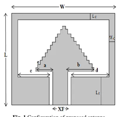
Antenna shape is obtained by creating a cavity into a ground plane. The ground plane is extended from partial ground to antenna encasing ground. The antenna structure is designed and simulated on FR4 epoxy with a dielectric constant of 4.4 and height of 0.8 mm. Antenna shape is made up of multiple strips that can be treated as dipoles fed at the center. All these dipoles can be mathematically analyzed, using equations of Hertzian dipole [24]. There are total twelve such dipoles included in the design, the biggest having the length of 11 mm and every adjacent dipole is one mm smaller than the last. Radiation excitation will be equivalent to the simple LC resonant circuit. Since we have used lumped port, it behaves as a current source with the matched impedance of 50 ohms in shunt [25].
Now, the band can be fine-tuned to our requirement based on the window or cavity size created in the ground plane. The proposed antenna structure uses the partial ground plane for the feed and this is also extended in order to surround antenna from all the three sides as shown in the Fig. 1. The empty part in the ground plane or metal is referred to as cavity or window whose size can be optimized in terms of its length and width. In this case, the design target is to optimize the cavity size so as to operate an antenna from 3.1 to 10.6 GHz. Considering average wavelength of an ultra-wideband operational band, dimensions of the antenna in terms of wavelength can be given 0.3λ×0.305λ×0.1λ.
3 Establishing the Problem
Now that the problem has been established, the resonance frequency and operating bandwidth can be optimized by changing the cavity size. Different simulations were carried out to change the bandwidth. There are three major dimensions of the cavity to be changed for antenna tuning: cavity length (Lc), cavity
width (Wc) and feed ground length (Lf). If such design is
to be done by trial-and-error method [26], it will take a large number of design iterations and design time
Fig. 1 Configuration of proposed antenna.
Table 1 Antenna dimension parameter to be considered for PSO.
Parameter L W LC WC Lf XF
Unit [mm] 24 24.4 2 2 9.8 2.6
Parameter a b c d e –
Unit [mm] 5.5 11 8.5 8.5 0.5 –
involved will be very high. In such case, the author had decided to go with particle-swarm-optimization (PSO) algorithm [27-28] to obtain the relation between cavity dimensions and bandwidth of the antenna. Particle swarm optimization algorithm takes the best-fit samples from the data set and provides the mathematical relation. More on the PSO algorithm in the later section. Simulation results from these limited number of iterations can be used to match the results as per required target. Showing important observation done during this design is that the PSO algorithm greatly reduces design time, design iterations and provides firm, mathematical basis for entire analysis.
Simulations are carried to vary one dimension of the cavity while keeping other two constants. Lc is varied
from 0.5 to 3.5 mm with Wc and Lf constants. Results
are compiled and near-best Lc dimension is selected. Wc
Variations are carried out from 2 to 6 mm in steps of 2 mm keeping other two dimensions constant. Lastly, Lf
variation carried out from 6 to 11 mm with other two dimensions constant. Near best- fit results are selected which will later be used to apply PSO algorithm. All the results are shown in Tables 1, 2 and 3. The compiled graphs are plotted in subsequent figures below.
The Tables 2, 3 and 4 show the effect of change in antenna dimensions in to antenna operating bandwidth.
4 PSO
The next step was to obtain the required sample data points. These data points were obtained from simulations done in the previous section. This section describes the mathematical foundation that has been
Iranian Journal of Electrical and Electronic Engineering, Vol. 15, No. 2, June 2019 197
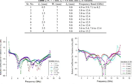
Table 2Wc = 7 mm, Lf = 9.8 mm; and Lc is variable.
Sr. No. Lc [mm] Wc [mm] Lf [mm] Frequency Band [GHz]
1 0.5 7 9.8 4.9 to 5.9; 7.1 to 8.2
2 1 7 9.8 3.8 to 12.6
3 1.5 7 9.8 3.8 to 13.6
4 2 7 9.8 3.9 to 12.4
5 2 3 9.8 4.2 to 11.6
6 2.5 7 9.8 4.2 to 12.5
7 3 7 9.8 4.2 to 12.6
8 3.5 7 9.8 3.6 to 5.4; 7.6 to 13.4
9 4 7 9.8 4.0 to 13.2
Fig. 2 Antenna return coefficient for variation in Lc before PSO. Fig. 3 Antenna return coefficient for variation in Lc before PSO.
Table 3Wc = 2 mm, Lf = 9.8 mm constant; and Lc is variable.
Sr. No. Lc [mm] Wc [mm] Lf [mm] Frequency Band [GHz]
1 2 2 9.8 3.5 to 11.4
2 3 2 9.8 5.6 to 11.6
3 4 2 9.8 5.8 to 13.6
4 5 2 9.8 3.4 to 12.4
5 6 2 9.8 3.6 to 12.2
Table 4Lc = 2 mm, Wc = 2 mm; and Lf is variable.
Sr. No. Lc [mm] Wc [mm] Lf [mm] Frequency Band [GHz]
1 6 2 2 3.6 to 11.6
2 7 2 2 2.8 to 11.6
3 9 2 2 3.2 to 11.7
4 10 2 2 3.5 to 11.4
5 11 2 2 Invalid
provided to entire analysis and design. As the most basic antenna theory suggests, an antenna will be treated as made of infinitesimally small dipoles and will be treated accordingly. The optimization target is to achieve return coefficient less than -10 dB for 3.1 to 10.6 GHz operating band. In problems like these, we cannot use integration and differentiation or even statistical methods because such problems do not deal with finding minima and maxima. Genetic algorithms (GA) are the most suitable [29] for such problems. James Kennedy and Robert Eberhart presented PSO algorithm in 1995 [30], which basically dealt with the behavior of a flock of birds or a school of fish or a colony of bees. But actually, this algorithm takes several parameters and sample points into consideration to
match to best suitable response. In antenna design and optimization problems like the one in this paper, generated sample data points are used to match to the desired response. This needs the derivation of the specific function, known as fitness function [31]. One important thing to be noted here is that, though antenna geometry is same and an algorithm is generic, the fitness function can be a unique to a particular problem. That bandwidth optimization fitness function can be different from gain improvement fitness function for the same antenna. This is another important observation noted in this design.
Assume that a sample point has the specific position on bandwidth mapping denoted as, xm and this point’s
movement can be controlled by velocity denoted by vm,
Iranian Journal of Electrical and Electronic Engineering, Vol. 15, No. 2, June 2019 198
which is influenced by antenna dimensions and parameters as established in the previous section. Now, this sample point will always try to find it the best possible location, which is global best. Our global best can be defined as criteria to set the return coefficient below -10 dB for desired this operating frequency band of 3.1 to 10.6 GHz. It is to be taken care that algorithm is continuous; the means any set of samples can take defined value in a given set. An advantage of this fact is that we can fine tune to the antenna bandwidth performance to the required frequency. A shortcoming of this algorithm is all the points and responses will be arranged in a specific set of the fitness function. Pseudo-steps in the fitness function derivation can be noted as:
1. Define the solution space.
2. Define the algorithm termination criteria: number of iterations or convergence of all points.
3. Define fitness function.
4. Randomly initialize xm and vm for all set of samples
5. Calculate best possible fitness for each of the sample points.
6. Repeat till get/achieve fitness function, which is calculated for all the points in a sample set. Next position for any given point can be given mathematically as, x(t+∆t) = x(t) + v(t)∆t. The major
Fig. 4 Antenna return coefficient for variation in Lf before
PSO.
Fig. 5 Simulation structure and sequence.
focus of the optimization problem using PSO algorithm is to calculate velocity or in other words, a rate of change of geometry response with respect to parameter changes. The frequency range for antenna simulation was taken from 1 to 15 GHz in steps of 200 MHz, which yields us 72 points. This forms the required sample points set. Boundary conditions need to be set here for termination of an algorithm. Boundary conditions then can be set as return coefficient varies from -9 dB to -18 dB in a desired frequency range, any point moving out of the set is either omitted or forced back into the required range. The MATLAB code is built for above-described algorithm and antenna simulation was carried out in HFSS.
When Microstrip or printed antenna shape becomes different from the standard geometrical shapes, it becomes difficult to model the antenna mathematically. The theory of infinitesimal dipoles helps such case. The designed algorithm works in a way to match the antenna response and can alter physical representation. General working is explained in Fig. 5.
The target of this PSO is to optimize the bandwidth and set proper resonance band of operation. Current and voltage at antenna input are assumed to in phase,
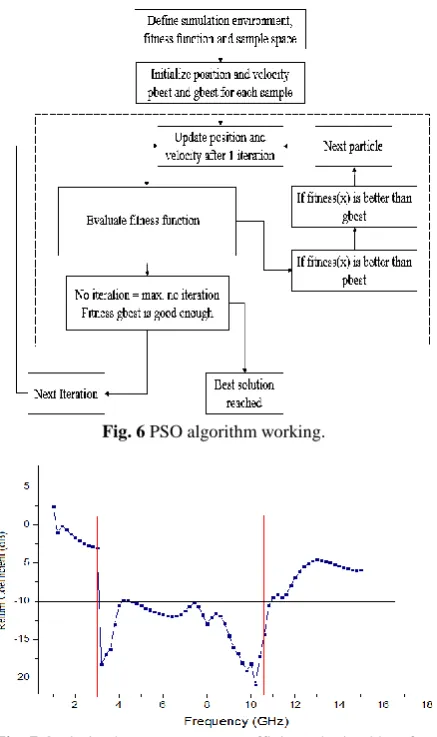
Fig. 6 PSO algorithm working.
Fig. 7 Optimized antenna return coefficient obtained by after applying PSO.
Iranian Journal of Electrical and Electronic Engineering, Vol. 15, No. 2, June 2019 199
ideally. The algorithm was designed to terminate after 32 iterations. The entire flow of working is shown in Fig. 6.
Once the algorithm was run for a designated number of iterations, the polynomial coefficients are obtained to derive the desired bandwidth.
5 Results and Discussion
Once the algorithm was run for a designated number of iterations, the polynomial coefficients are obtained to derive the desired bandwidth. The results obtained were used to optimize the simulation and plot the final response of the antenna. The desired bandwidth is 3.1 to 10.6 GHz. As can be seen from markers in the graph, of a simulated graph shown in Fig. 7, the bandwidth covered by the designed antenna is 3.1 to 10.6 GHz obtained by PSO. This optimized antenna is fabricated and tested against the simulation results. Simulated, optimized and fabrication results were found to be in agreement.
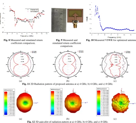
As it can be seen from the Fig. 8, measured return coefficient is in agreement to simulated value of return coefficient Antenna hardware may produce few fluctuations in the return coefficient measurements due to reasons like fabrication errors and measurement accuracy. However, in general, measured results are close to simulated results.
Average value of VSWR obtained for an entire ultra-wideband is 2, as seen from Fig. 10. As shown in Fig. 11, the simulated 2D radiation patterns for the omnidirectional characteristics at E-plane and H plane of proposed UWB antenna at 4 GHz, 6 GHz, and 8 GHz are plotted. The patterns are an antenna with a maximum gain of about 3.33 dB for 4 GHz, 4.86 dB for 6 GHz, and 3.97 dB for 8 GHz. In Fig. 12 shows 3D plots of the radiation patterns and gain values of the proposed antenna at three frequencies 4, 6 and 8 GHz. Figures imply that the results have reasonable omnidirectional radiation patterns.
Fig. 8 Measured and simulated return coefficient comparison.
Fig. 9 Measured and simulated return coefficient
comparison.
Fig. 10 Measured VSWR for optimized antenna.
(a) (b) (c)
Fig. 11 2D Radiation pattern of proposed antenna at a) 4 GHz, b) 6 GHz, and c) 8 GHz.
(a) (b) (c)
Fig. 12 3D gain plot of radiation pattern at a) 4 GHz, b) 6 GHz, and c) 8 GHz.
Iranian Journal of Electrical and Electronic Engineering, Vol. 15, No. 2, June 2019 200
Fig. 13 Efficiency vs. frequency plot of proposed antenna.
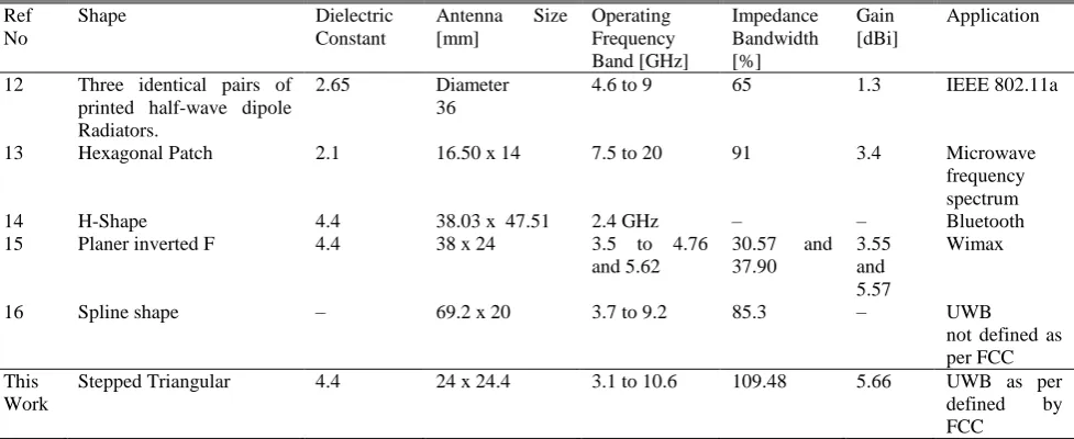
Table 5 Comparison of the results and other given by PSO Paper.
Ref No
Shape Dielectric
Constant
Antenna Size [mm]
Operating Frequency Band [GHz]
Impedance Bandwidth [%]
Gain [dBi]
Application
12 Three identical pairs of printed half-wave dipole Radiators.
2.65 Diameter 36
4.6 to 9 65 1.3 IEEE 802.11a
13 Hexagonal Patch 2.1 16.50 x 14 7.5 to 20 91 3.4 Microwave
frequency spectrum
14 H-Shape 4.4 38.03 x 47.51 2.4 GHz – – Bluetooth
15 Planer inverted F 4.4 38 x 24 3.5 to 4.76 and 5.62
30.57 and 37.90
3.55 and 5.57
Wimax
16 Spline shape – 69.2 x 20 3.7 to 9.2 85.3 – UWB
not defined as per FCC This
Work
Stepped Triangular 4.4 24 x 24.4 3.1 to 10.6 109.48 5.66 UWB as per defined by FCC
As shown in Fig. 13, over the UWB range, it has the efficiency of 61-88% which implies that the result of efficiency is appropriate for all UWB applications. Table 5 concludes the performances of the proposed antenna with other reported PSO based antennas. It is discovered that the operating frequency and gain of the proposed antenna are higher compared to [12–16]. The proposed antenna consists of a small compact size which is easier to fabricate for UWB applications.
6 Conclusion
This paper proposes a Novel shape Ultra-wideband (UWB) antenna bandwidth optimization using Particle Swarm Optimization algorithm. The antenna is simulated and fabricated on the low-cost material of a FR 4 substrate. The antenna system has compact dimensions of the in terms of wavelength as 0.3λ×0.305λ×0.1λ. An ultra-wideband antenna is designed and simulated based on a theory of infinitesimal dipoles. Its response is optimized using
PSO algorithm to fit into the desired band of 3.1 to 10.6 GHz using the sample set of points obtained. Within the operating bandwidth of the antenna obtains a maximum gain of 5.66 dB. The antenna system is analyzed in term of return loss (S11), VSWR, radiation pattern and gain. Due to the compact size, good gain, and UWB bandwidth the proposed antenna is suitable for UWB wireless application.
References
[1] G. Breed, “A summary of FCC rules for ultra-wide band communications,” High Frequency Electronics, Vol. 1, pp. 42–45, Jan. 2005.
[2] C. C. Lin, Y. C. Kan, L. C. Kuo, and H. R. Chuang, “A planar triangular monopole antenna for UWB communication,” IEEE Microwave and Wireless Components Letters, Vol. 15, No. 10, pp. 624–626, Oct. 2005 .
Iranian Journal of Electrical and Electronic Engineering, Vol. 15, No. 2, June 2019 201
[3] M. C. Tang, T. Shi, and R. W. Ziolkowski, “Planar ultra wideband antennas with improved realized gain performance,” IEEE Transactions on Antennas and Propagation, Vol. 64, No.1, pp. 61–69, Jan. 2016. [4] D. Chen and C. H. Cheng, “A novel compact
ultra-wideband (UWB) wide slot antenna with via holes,”
Progress in Electromagnetics Research, Vol. 94, pp. 343–349, 2009.
[5] R. Zaker, C. Ghobadi, and J. Nourinia, “Novel modified UWB planer Monopole Antenna with Variable Frequency Band-Notch Function,” IEEE Antennas and Wireless Propagation Letters, Vol. 7, pp. 112–114, May 2008.
[6] J. Jung, W. Choi, and J.Choi, “A small wideband microstrip-fed monopole antenna,” IEEE Microwave and Wireless Components Letters, Vol. 15, No.10, pp.703–705, Oct. 2005.
[7] K. Chung, H. Park, and J. Choi, “Wideband microstrip-fed monopole antenna with a narrow slit,” IEEE Microwave and Optical Technology Letters, Vol. 47, pp. 400–402 Sep. 2005.
[8] D. Guha and Y. Antar, “Circular microstrip patch loaded with balanced shorting pins for improved bandwidth,” IEEE Antennas and Wireless Propagation Letters, Vol. 5, No. 1, pp. 217–219, May 2006.
[9] X. Jiang, S. Li, and G. Su, “Broadband planar antenna with parasitic radiator,” Electronics Letters,
Vol. 39, No. 23, Dec. 2003.
[10]E. A. Daviu, M. C. Fabres, M. F. Bataller, and A. V. Nogueira, “Wideband double-fed planar monopole antennas,” Electronics Letters, Vol. 39, No. 23, 2003.
[11]V. Sadeghi, C. Ghobadi, and J. Nourinia, “Design of UWB semi-circle-like slot antenna with controllable band-notch function,” Electronics Letters, Vol. 45, No. 25, pp. 1282–1283, Dec. 2009. [12]C. Yu, T. Xu, and C. Liu, “Design of a Novel UWB
Omnidirectional Antenna Using Particle Swarm Optimization,” International Journal of Antennas and Propagation, Vol. 2015, pp. 1–7, May 2015. [13]A. Bhattacharya, B. Roy, M. Islam1,
S. K. Chowdhury, and A. K. Bhattacharjee, “An UWB monopole antenna with hexagonal patch structure designed using particle swarm optimization algorithm for wireless applications,” in IEEE-International Conference on Microelectronics, Computing and Communications (MicroCom),
Jan. 2016.
[14]C. Rai and S. Lal, “Optimization of h-shape micro strip patch antenna using PSO and curve fitting,”
International Journal for Research in Applied Science & Engineering Technology (IJRASET),
Vol. 5, No. X, pp. 993–996, Oct. 2017.
[15]L. Wakrim and S. Ibnyaich, “The study of the ground plane effect on a multiband PIFA antenna by using genetic algorithm and particle swarm optimization,” Journal of Microwaves, Optoelectronics and Electromagnetic Applications, Vol. 15, No. 4, Dec. 2016.
[16]L. Lizzi, F. Viani, and R. Azaro, “Optimization of a spline-shaped UWB antenna by PSO,” IEEE Antennas and Wireless Propagation Letters, Vol. 6, pp. 182–185 Apr. 2007.
[17]Y. L. Li, W. Shao, L. You, and B. Z. Wang, “An improved PSO algorithm and its application to UWB antenna design,” IEEE Antennas and Wireless Propagation Letters, Vol. 12, pp. 1236–1239, Sep. 2013.
[18]S. L. Avila and W. P. Carpes, “Optimization of an offset reflector antenna using genetic algorithms,”
IEEE Transactions magnetics, Vol. 40, No. 2, pp.1256–1259, Mar. 2004.
[19]Z. N. Low, J. H. Cheong and C. L. Law, “Low-cost PCB antenna for UWB applications,” IEEE Antennas and Wireless Propagation Letters, Vol. 4, pp. 237–239, 2005.
[20]R. Azim, M. T. Islam, and N. Misran, “Compact tapered-shape slot antenna for UWB applications,”
IEEE Antennas and Wireless Propagation Letters,
Vol. 10, pp. 1190–1193, Oct. 2011.
[21]K. S. Ryu and A. A. Kishk, “UWB antenna with single or dual band-notches for lower WLAN band and upper WLAN band,” IEEE Transactions on Antennas and Propagation, Vol. 57, No. 12, pp. 3942–3950, Dec. 2009.
[22]J. Liang, C. C. Chiau, X. Chen and C. G. Parini, “Study of a printed circular disc monopole antenna for UWB systems,” IEEE Transactions on Antennas and Propagation, Vol. 53, No. 11, pp. 3500–3504, Nov. 2005.
[23]M. M. Samadi Taheri, H. R. Hassani and S. Mohammad Ali Nezhad, “UWB printed slot antenna with bluetooth and dual notch bands,” IEEE Antennas and Wireless Propagation Letters, Vol. 10, pp. 255–258, Feb. 2011.
[24]H. G. Schantz,” Electromagnetic energy around Hertzian dipoles,” IEEE Antennas and Propagation Magazine, Vol. 43, No. 2, pp. 50–62, Apr. 2001.
Iranian Journal of Electrical and Electronic Engineering, Vol. 15, No. 2, June 2019 202
[25]P. Jin and R. W. Ziolkowski, “Broadband, efficient, electrically small metamaterial-inspired antennas facilitated by active near-field resonant parasitic elements,” IEEE Transactions on Antennas and Propagation, Vol. 58, No. 2, pp. 318–327, Feb. 2010.
[26]M. Abbosh and M. E. Bialkowski, “Design of ultrawideband planar monopole antennas of circular and elliptical shape,” IEEE Transactions on Antennas and Propagation, Vol. 56, No. 1, pp. 17– 23, Jan. 2008.
[27]M. T. Islam, N. Misran, T. C. Take and M. Moniruzzaman, “Optimization of microstrip patch antenna using particle swarm optimization with curve fitting,” International Conference on Electrical Engineering and Informatics, Selangor, pp. 711-714, Aug. 2009.
[28]R. A. Formato, “Improved CFO algorithm for antenna optimization,” Progress in Electromagnetics Research B, Vol. 19, pp. 405–425, Oct. 2010.
[29]S. C. Panagiotou, S. C. Thomopoulosand, and C. N. Capsalis, “Genetic algorithms in antennas and smart antennas design overview,” International Journal of Antennas and Propagation, Vol. 2014, pp.1–13, Dec 2014.
[30]V. Rajpoot, D. K. Srivastava, and A. K. Saurabh, “Optimization of I-shape microstrip patch antenna using PSO and curve fitting,” Journal of Computational Electronics, Vol. 13, No. 4, pp. 1010–1013 Dec. 2014.
[31]Y. Shi and R. C. Eberhart, “Empirical study of particle swarm optimization,” in Proceedings of the 1999 Congress on Evolutionary
Computation-CEC99 (Cat. No. 99TH8406), Washington, pp. 1945–1950, Jul. 1999.
M. A. Trimukhe was born in Mumbai, India. He received his Bachelor degree in Electronics and Telecommunication from Dr. BAMU, Aurangabad, and Master Degree in Electronics and Telecommunication from Mumbai University. Presently he is working as an Assistant Professor in the Department of Electronics and Telecommunication Engineering at Terna Engineering College, Nerul, Navi Mumbai. His major research interest is designing of patch antenna, UWB antennas, and metamaterials.
B. Hogade received his Bachelor degree in Electronics from Dr. BAMU, Aurangabad, Master Degree in Power Electronics from Gulbarga University and Ph.D. degree from SVKM’S NMIMS MPSTME, Mumbai. He is currently working as a Professor in the Department of Electronics Engineering at Terna Engineering College, Nerul, Navi Mumbai. His research interests include smart antennas, UWB antennas designing, wireless communication, and microwave devices.
© 2019 by the authors. Licensee IUST, Tehran, Iran. This article is an open access article distributed under the terms and conditions of the Creative Commons Attribution-NonCommercial 4.0 International (CC BY-NC 4.0) license (https://creativecommons.org/licenses/by-nc/4.0/).