280
Response of a columnar vortex to a wrapped vortex loop
J.S. Marshall
Iowa Institute of Hydraulic Research and Department of Mechanical Engineering, The University of Iowa Iowa City, Iowa, U.S.A., [email protected]
Abstract
A computational and experimental study of the interaction between an initially columnar vortex and a wrapped vortex loop was performed, which focused on the columnar vortex response to the vortex loop. This problem is motivated by applications involving three-dimensional vortex interaction with a solid body, where the secondary vorticity shed from the body rolls up into a series of loop-like structures that are advected away from the body by the primary vortex. As a secondary vortex loop wraps around a columnar vortex, it becomes entrained into the vortex core due to the self-induced velocity of the loop. The columnar vortex response as a secondary vortex loop moves close to and impacts upon its lateral core surface includes a combination of bending waves, waves of variable core area, and core shape deformation. If a vortex loop is sufficiently strong, its interaction with the columnar vortex is also accompanied by ejection of vorticity from the columanr vortex, sometimes leading to development of a traveling vortex breakdown.
Introduction
The wrapping of vortex loops around a larger-scale vortex structure is an ubiquitous interaction, occurring in nearly any situation involving vortex structures of different sizes or strengths interacting in three dimensions. A common example of this interaction is observed in problems where a large-scale vortex is immersed in a sea of smaller-scale turbulence, as observed for instance when aircraft trailing vortices are exposed to atmospheric turbulence or when ship wake vortices interact with turbulence shed from the free surface. More fundamental still is the interaction between the large-scale coherent eddies that are found in many turbulent flows and the smaller-scale background turbulence of the flow. In such examples, the eddies of the background turbulent flow wrap around the larger-scale vortex in the shape of loop structures, characterized by a "head" and two "legs", as observed both in direct numerical simulations [1] and in wind tunnel experiments [2]. In such situations, the background turbulence dominates turbulence production and decay of the large-scale eddy [3-5].
Our interest in the loop-columnar vortex interaction arose principally from studies of the three-dimensional viscous response of a solid body in the presence of vortex structures. This problem is of particular importance in rotorcraft aerodynamics, where the vehicle fuselage and tail are often immersed in the main rotor wake. A series of flow visualization experiments of normal vortex-body interaction, shown schematically in fig. 1, have been performed at Iowa using a circular cylinder [6], a thin blade [7,8] and a sphere [9] to represent the body. These experiments were conducted using a combination of two-color laser-induced fluorescence (LIF) and particle-image velocimetry (PIV) in water. In the experiments, a columnar intake vortex is formed in a cylindrical tank, and a solid body is towed towards the vortex. The experiments show that if the towing speed of the body is sufficiently fast, then no separation of the body boundary layer will occur prior to impact with the vortex and the vortex response to the body will be dominated by inviscid effects. On the other hand, if the body towing speed is sufficiently slow (compared to the maximum vortex swirl velocity), a series of secondary vortex loops are shed from the body and wrap around the primary vortex.
three-dimensional loop with a columnar vortex is computed during one cycle of rotation in order to examine the effect of the loop nose during the early stages of the wrapping process. Conclusions are presented in section 4.
1 Examples From Vortex-Body Interaction Experiments
In the vortex-body interaction experiments, a solid body is translated at a speed U through a vertical intake vortex with strength Γ and average downward axial flow
w
0. The vortex is generated in water in a cylindrical inner tank, about which is placed an outer rectangular tank that houses the body and support arms of the tow carriage. Water is circulated through the system via tangential inlet jets at the top of the inner cylindrical tank and an outlet orifice at the tank bottom. The intake vortex is trapped at the top of the cylindrical tank by an inverted funnel, which both stabilizes the vortex and increases the core radius. The vortex is supplied dye (which fluoresces red) from the top through the inverted funnel center, and the body boundary layer is supplied dye (which fluoresces yellow) through a series of small holes in the body surface. The flow rate of yellow dye is finely controlled by adjusting both the gravity head of the dye reservoir and a needle valve placed in the feed line. The flow is illuminated using either argon or Nd:YAG lasers, and photographs are obtained using both a 35 mm still camera and an ordinary 30 Hz video camera. The vertical and horizontal imaging planes, labeled A and B, respectively, are shown in fig. 1. For vortex-cylinder interaction problems, where the vortex can become significantly bent during the interaction, the vertical imaging plane is usually displaced in the spanwise direction so as to pass through the vortex center at the time of impact with the body.The vortex azimuthal velocity component is measured using PIV in the cross-sectional plane B, and the vortex axial velocity profile is measured by photographing the motion of small (0.5-1 mm diameter) neutrally buoyant immiscible dye globules released into the vortex core. For all experiments reported in the paper, the vortex has axial velocity w0 =131±15mm/s, core radius σ0 =4.0±1.0mm, and strength
s mm / 10
1 10
24× 3 ± × 3 2
=
Γ . At heights near the body location, the radial component of the ambient vortex velocity field is very small – less than 1% of the azimuthal velocity component. The towing velocity U is varied from 25 mm/s to 300 mm/s for experiments with a circular cylinder or a blade. For the sphere experiments, the body is towed toward the vortex and gradually brought to rest at a specified distance S between the sphere leading edge and the vortex center axis. Normal vortex interaction with an elongated cylinder or blade is governed by four dimensionless parameters: the impact parameter I=2πσ0U/Γ, the thickness parameter T=D/σ0 (where D is a measure of the body thickness), the vortex Reynolds number
ν
Γ
≡
/
Re
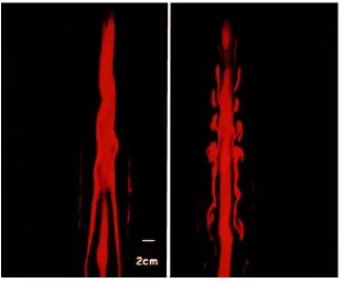
v (where ν is the kinematic viscosity) and the axial flow parameter A=2πσ0w0/Γ. For experiments with a sphere, the impact parameter I is replaced by the ratio S /D of vortex-sphere separation distance to sphere diameter. For all experiments, the axial flow parameter is A=0.20±0.06 and the vortex Reynolds number is ReV ≅2.5×10⁴.For the case of a blade or cylindrical body, the body wake does not play an important role in the vortex-body interaction. It is observed with these bodies that if the maximum vortex swirl velocity Γ/2πσ0 is sufficiently large compared to the body towing speed U, vorticity will be ejected from the leading edge of the body and drawn outward by the vortex-induced flow. This secondary vorticity quickly rolls up into a series of vortex loops, located at different positions along the body span. For example, an LIF image showing a view of the secondary vortical loops with volumetric imaging is given in fig. 2 for the case of a blade-shaped body towed toward a vortex with I=0.037
and
T=1.6.
alternating sign [10]. In the presence of a columnar vortex, the vortex loops in the wake reorient themselves such that their self-induced velocity draws the sphere wake into the columnar vortex core as it wraps around the vortex. The loops also become highly stretched and their separation distance increases as they move closer to the columnar vortex.
Relatively weak vortex loops cause formation of small-amplitude waves of variable core area on the primary vortex, but do not significantly disrupt the vortex. After long time, the weak vortex loops form a turbulent sheath around the columnar vortex core. Sufficiently strong vortex loops, on the other hand, can have a dramatic effect on the primary vortex. An example showing the interaction of a relatively strong vortex loop shed from a sphere with a columnar vortex is given in fig. 4, which is obtained using LIF in the vertical plane A. The sphere, which has diameter D=19.2mm, is brought to rest at a vortex-sphere separation distance S=38.5mm, such that D/σ0 =4.8 and S/D=2. The vortex loop causes thinning of the primary vortex in the region in-between the loop legs and bulging of the vortex outside of this region. Fluid is ejected from the primary vortex and wraps around the vortex loop. A section of the flow, indicated by a white rectangle, was examined using PIV, and results for the velocity vectors and streamlines within this region are shown in fig. 5a-b. The ratio of vortex loop strength to the strength of the primary vortex for this case is 0.18±0.02. In general, it is difficult to use PIV for measurement of the vortex loop flow field, except for cases with relatively strong vortex loops, due to the strong out-of-plane flow induced by the swirl of the primary vortex.
For cases with sufficiently strong vortex loops, such as that shown in fig. 4, the wrapping of the loops around the primary vortex induces formation of a traveling vortex breakdown that propagates upstream on the vortex core. An LIF photograph of the vortex breakdown is given in fig. 6 for a sphere-vortex interaction with D/σ0 =4.8 and S/D=1. The photograph is obtained using a vertical imaging plane located at a distance 27 cm upstream of the sphere. The flow is shown for times when the breakdown nears the center of the imaging plane and after the breakdown has propagated through the imaging plane. The breakdown is observed to have a spiral form, as indicated by the kink in the red dyed fluid observed in fig. 6a. This vortex spiral is followed by a train of ring-like turbulent structures wrapped around the vortex, as indicated by the nearly periodic ejections of red dyed fluid in fig. 6b.
2 Axisymmetric Computations
An initial set of computations of the loop-columnar vortex interaction is performed using an axisymmetric model for the wake vortices (fig. 7), which approximates the interaction between the legs of the wake vortices after they have wrapped around the primary vortex and have evolved into an approximately ring-like shape. The objective of the computations is to illustrate the response of the vorticity field within the primary vortex to the stretching induced by the wake vortices. The computations are performed using the vortex method for axisymmetric swirling flows proposed by Marshall and Grant [11], which uses a combination of ring-like elements and blob-like elements for support of the vorticity field. Buffer regions are used at both ends of the computed flow, at the end of which vortex elements are either created or eliminated. All variables are non-dimensionalized using the columnar vortex core radius σ0 and strength Γ. The computational parameters are selected, based in part on experimental measurements with sphere-vortex interaction for the case shown in fig. 4, with ambient columnar vortex axial flow w0 =0.032, vortex ring core radius σR =0.5, ring separation distance L=2, ring radius R=2, and ring strength
3 . 0
=
ΓR .
of waves on the columnar vortex, with crests propagating both upstream and downstream away from the vortex pair. The vortex waves grow progressively steeper in time, eventually leading to outward ejection of vorticity from the columnar vortex.
One consequence of the variation in core radius is the production of azimuthal vorticity within the columnar vortex core. Azimuthal vorticity is generated when the initially axial vorticity vector is tilted in the radial direction by a variation in vortex core radius. Under the influence of the ambient radial variation in the azimuthal velocity of the vortex, the radial tilt in the vorticity vector leads to twisting of the vortex lines, since sections of the vortex lines at different radial distances will rotate at different rates. The azimuthal vorticity field is indicated by the velocity vector colors in fig. 9 for a time corresponding to that in fig. 8b. The majority of the azimuthal vorticity is generated within two strips, located near the lateral surface of the columnar vortex core with one strip positioned beneath each vortex ring. The sign of the azimuthal vorticity produced within each of these strips on the columnar vortex is opposite to that of the corresponding vortex ring.
The direction of the axial velocity within the primary vortex is indicated by the vector colors in figure 8a-c, where red indicates flow to the right and blue indicates flow to the left. The ambient axial velocity (in the absence of the rings) is directed to the right. Change in axial velocity from the ambient value is induced both by the two vortex rings and by the strips of azimuthal vorticity within the core of the columnar vortex. Because these strips of vorticity within the columnar vortex have azimuthal vorticity of a sign opposite to that of the associated vortex rings, the induced axial velocity from these two sources also has opposite signs near the center of the columnar vortex. For instance, we observe in fig. 8a that the induced velocity from the right-hand vortex ring acts to increase the ambient axial velocity within the columnar vortex, whereas the induced velocity from the left-hand ring opposes the ambient axial velocity and results in a back-flowing region within columnar vortex. At a later time (fig. 8b) the azimuthal vorticity strips within the columnar vortex have grown strong enough to induce a region of back flow on the columnar vortex below the right-hand vortex ring, which is opposite to the direction of both the ambient axial flow and the induced velocity from the right-hand vortex ring. This region of back flow propagates downstream (to the right) over time, as shown in fig. 8c. Similarly on the left-hand side, the azimuthal vorticity strip within the columnar vortex causes a region of forward flow to form underneath the left-hand vortex ring (fig. 8b), which is nearly surrounded by the region of back flow induced by the vortex ring. Over time, this region of forward flow is pushed upstream by the back-flowing wave induced by the left-hand vortex ring.
3 Three-Dimensional Computations
A three-dimensional numerical computation is reported for a single vortex loop wrapping around a columnar vortex with Gaussian vorticity distribution across the core. The objective of this calculation is to examine the effect of the nose region of the vortex loop on the columnar vortex during the early stage of the interaction. The vortex loop is initiated by an elliptical vortex ring, which is aligned with major axis normal to the columnar vortex and minor axis parallel to the columnar vortex. Variables are non-dimensionalized by the columnar vortex core radius σ0 and strength Γ. The values of the computational parameters are suggested by experimental data for vortex-blade interaction, such as shown in fig. 2. The elliptical vortex ring initially has semi-minor and semi-major axes of 2 and 5, respectively, core radius 0.5, and strength 0.2. The computed flow is assumed to be inviscid since the Reynolds number for the experiments (2 5 10
.
×
4) is large.only over the interval (-5,5) in the x-direction. Two "buffer regions" are placed in the intervals (−7,−5) and (5,7) in the x-direction within which both the position of the control points and the value of vorticity on these points are fixed. Within the regions
x
< −
7
andx
>
7
, the vorticity within the columnar vortex is approximated by a collection of 35 semi-infinite vortex filaments.For plotting purposes, the vorticity field is interpolated onto a uniform grid using the Gaussian vorticity elements in order to generate contour surfaces and vortex lines from the computed results. The grid for volumetric plots measures 51
×
41
×
47
(with point separation of 0.15), and the grids for surface plots measure 121 121×
for the y-z plane and 201 121×
for the x-y plane (with point separation of 0.05).A representative iso-vorticity magnitude surface (with
ω =
0 3
.
) is shown in fig. 10 at timest
=
35 4
.
and t=
59 4
.
. The nose of the vortex loop is observed to induce bending of the columnar vortex and to lead to pronounced distortion of the core cross-section. After sufficient time, vorticity from the columnar vortex is ejected by the induced flow from the vortex loop and wraps around the core of the vortex loop.Progression of the columnar vortex core shape distortion with time is evident in the vorticity magnitude contour plots of the vortex cross-section in the y-z plane (at
x
=
0) in fig. 11a-d. The nose of the
vortex loop rotates in the counter-clockwise direction about the columnar vortex, while the core of the vortex loop stretches and becomes smaller with time. The columnar vortex deforms due to the straining from the nose of the vortex loop. The elongated shape of the columnar vortex also rotates (as exemplified by the well-known Kirchhoff elliptical vortex patch [13]), which is apparent from a comparison of fig. 11c-d. A cross-section of an ejected ridge of vorticity from the columnar vortex core is evident in fig. 11c, which rotates in fig. 11d to the side of the columnar vortex opposite to the nose of the vortex loop.A contour plot of the azimuthal vorticity (ωz) is plotted in the x-y plane in fig. 12 at time t=59.4.
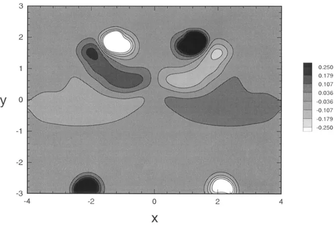
The azimuthal vorticity has opposite signs on the two halves of the columnar vortex, separated by the plane
x
=
0, with maximum azimuthal vorticity generated in the part of the columnar vortex that is raised by the
induced velocity from the vortex loop. The azimuthal vorticity that forms within the columnar vortex in the three-dimensional computations shows the same qualitative features as in the axisymmetric computations: two azimuthal vorticity strips are formed under each leg of the vortex loop with sign opposite to that of the respective loop cross-section.4 Conclusions
The wrapping of a vortex loop around a columnar vortex is shown to be a fundamental component of the vortex-body interaction problem, occurring as the secondary vorticity shed from the body is advected around and becomes entrained into the columnar vortex core. The loop-columnar vortex interaction is examined both in the course of vortex-body interaction experiments and with use of two different computational methods. The induced velocity from vortex loops that are much weaker than the columnar vortex induces small-amplitude waves of variable core area on the columnar vortex. When the vortex loop strength is sufficiently large, the response of the columnar vortex to the induced velocity from the vortex loops includes bending waves, deformation of core cross-sectional shape, and ejection of vorticity from the columnar vortex core. For cases with non-zero columnar vortex axial flow, a sufficiently strong vortex loop is observed to generate a traveling spiral-type vortex breakdown that propagates upstream on the columnar vortex.
Acknowledgements
and Dr. Srikanth Krishnamoorthy, who conducted the vortex-body interaction experiments described in section 1.
References
1 MELANDER, M.V. and HUSSAIN, F.: Coupling between a coherent structure and fine-scale turbulence. Phys. Rev. E 48 (1993), 2669--2689.
2 BANDYOPADHYAY, P.R., STEAD, D.J. and ASH, R.L.: Organized nature of a turbulent trailing vortex. AIAA J. 29 (1991), 1627--1633.
3 TOMBACH, I.: Observations of atmospheric effects on vortex wake behavior. J. Aircraft 10 (1973), 641--646.
4 SARPKAYA, T. and DALY, J.J.: Effect of ambient turbulence on trailing vortices. J. Aircraft 24 (1987), 399--404.
5 LIU, H.T.: Effects of ambient turbulence on the decay of a trailing vortex wake. J. Aircraft 29 (1992), 255--286.
6 KRISHNAMOORTHY, S., GOSSLER, A.A. and MARSHALL, J.S.: Normal vortex interaction
with a circular cylinder. AIAA J. 37(1) (1999), 50--57.
7 MARSHALL, J.S. and KRISHNAMOORTHY, S.: On the instantaneous cutting of a columnar
vortex with non-zero axial flow. J. Fluid Mech. 351 (1997), 41--74.
8 KRISHNAMOORTHY, S. and MARSHALL, J.S.: Three-dimensional blade-vortex interaction in
the strong-vortex regime. Phys. Fluids 10(11) (1998), 2828-2845.
9 SUN, M.: A study on vortex interaction with a sphere wake. M.S. thesis, University of Iowa, Iowa City, USA (1998).
10 ACHENBAUCH, E.: Vortex shedding from spheres. J. Fluid Mech. 62 (1974), 209--221.
11 MARSHALL, J.S. and GRANT, J.R.: A Lagrangian vorticity collocation method for viscous, axisymmetric flows with and without swirl. J. Computat. Phys. 138 (1997), 302--330.
12 MARSHALL, J.S. and GRANT, J.R.: Penetration of a blade into a vortex core: vorticity response and unsteady blade forces. J. Fluid Mech. 306 (1996), 83--109.
Fig. 1. Schematic of normal vortex interaction with a circular cylinder, showing the vertical [A] and horizontal [B] imaging planes used for LIF and PIV.
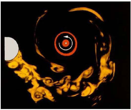
Fig. 3. LIF photograph in the horizontal plane B illustrating entrainment of the wake of a sphere (yellow) into a columnar vortex core (red).
Fig. 5. PIV results for velocity vectors and streamlines within the region indicated by a rectangle in fig. 4, covering a cross-section of a vortex loop.
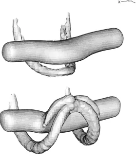
Fig. 7. Schematic showing an axisymmetric model of the vortex loop legs, represented by vortex rings of opposite sign, wrapped around a columnar vortex.
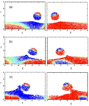
Fig. 9. Computational results showing the azimuthal vorticity generation within the columnar vortex due to the velocity generated by the vortex loop legs using an axisymmetric model. The vectors represent the velocity components in the r-z plane and colors indicate the azimuthal vorticity.
Fig. 11. Contour plots (in the x-y plane) of the vorticity magnitude showing deformation of the vortex core shape and vorticity ejection caused by wrapping of a vortex loop.
Fig. 12. Contour plot of the azimuthal vorticity (ωz) in the x-y plane for a three-dimensional vortex loop

![SIFT (Søking I Fri Tekst) – Et generelt informasjonssøkesystem (SIFT (Search in Free Text) – A general information retrieval system) [In Norwegian]](data:image/gif;base64,R0lGODlhAQABAIAAAP///wAAACH5BAEAAAAALAAAAAABAAEAAAICRAEAOw==)