1 Available online at www.ijiere.com
International Journal of Innovative and Emerging
Research in Engineering
e-ISSN: 2394-3343 p-ISSN: 2394-5494
Implementation of Artificial Intelligence Technique to
Regulate a DC-DC Converter for Transient Compensation
Priyambada Shahi
a, Divya Singh Chouhan
band VikramadityaDave
c aC.T.A.E, M.L.S University Campus, Udaipur, Rajasthan bC.T.A.E, M.L.S University Campus, Udaipur, RajasthancC.T.A.E, M.L.S University Campus, Udaipur, Rajasthan
ABSTRACT:
This paper presents a neural network control scheme for a boost converter. The proposed method regulates the output voltage and mitigates the transients in the output waveform. To investigate the performance of the proposed approach, boost converter circuits with different ratings have been tested. The results show that the proposed approach gives better results than that of a PI controller.
Keywords: Boost converter, Neural network, PI controller, Performance comparison, MATLAB
I. INTRODUCTION
A. Boost Converter
A boost converter is a DC-DC converter that boosts (steps up) the output voltage. A boost converter is a veryimportant device as it is the only DC-DC voltage step up device. Fig 1 shows the diagram of a typical boost converter.
Figure1: Schematic diagram of a typical boost converter
A boost converter is well known for its high efficiency,low costand small size. Some of the applications of a boost converter are -computers, power factor correction methods, hybrid photovoltaic (PV)/wind power system applications, piezoelectric energy harvesting systems, photovoltaic applications, vehicular systems, fuel cell applications etc. When a boost converter is operated in open loop, the voltage regulation is quite poor. It also contains considerableamount of transients. In order to obtain a good voltage regulation and to control the voltage dynamics, a feedback controller should be accurately designed. There are different types of feedback controller available. Few of them are PI(Proportional Integral), PD (Proportional Derivative) and PID (Proportional Integral Derivative) controllers.Switching of the converter is usually done with Pulse Width Modulator.
B. Pulse Width Modulation (PWM) Controller
2 A PWM controller uses PWM technique, which is changing the output by changing the duty cycle (ton/toff) while keeping
the frequency constant. It is the most commonly used duty ratio control method. The applications range from alleviating the problem of high heat loses through resistances at intermediate voltage points, voltage regulation, power delivery, controlling actuators, telecommunication to amplificationetc. Figure 2 shows a PWM controller for a boost converter. C. Conventional Controllers
The conventional controllers include PI, PD, PID controllers etc. The DC-DC converters consist of semiconductor devices that operate as switches and the converters are classified as switched-mode DC-DC converters or referred to as Switched Mode Power Supply (SMPS). The conventional controllers assume all circuit components asidealwith no power loss and no performance degradation and the circuit is operated at a stable bias point so that it canbe modelled by a set of linear equations [2]. However, in practice the switching network is highly nonlinear. Anaccuratemathematical model of the switching network is very difficult to design. Even if the accurate models are operated with the conventional controllers, there are reported problems of supply voltage and load current fluctuations over a wide range. This brings into picture the artificially intelligent techniques that are adaptive in nature and can provide a better solution to the problem. Nowadays, even the conventional controllers are operated with intelligent techniques.
D. Artificial Neural Network (ANN)
Figure3: Structure of a typical neural network
An (Artificial Intelligence) AI controller is a ‘non-model based’ controller. Some of its examples are Fuzzy logic, Ant Algorithm, Genetic Algorithm (GA), Particle Swarm Optimization (PSO), Artificial Immune Systems (AIS), Artificial Neural Network (ANN) etc. Although GA and Fuzzy logic have been very popular since a long time, it is being replaced by ANN in most of the cases. The reason being the Fuzzy logic solution at all the operating conditions is quite difficult to achieve since it is a trial-and-error method [4]. In addition this method is also time consuming. When online tuning algorithm is used, the results obtained are satisfactory but the computation is very complex [3].
II. SOLUTIONTOTHEPROBLEM
The output voltage of a boost converter is needed to be controlled. Hence a proper non-linear modelling of the converter is required. Thereare three modes of operation of a boost converter. The MOSFET is represented as T and the diode as D. The modes are [1]:
Mode 1: T state-on and D state-off Mode 2: T state-off and D state-on Mode 3: T and D state-off
The variation of the voltage across the inductance L (equation 1) and the current through the capacitor (equation 2) depends upon the operating phase.
𝑣𝐿(𝑡) = 𝑣𝑖(𝑡) ∗ 𝐹 + (𝑣𝑖(𝑡) − 𝑣0(𝑡)) ∗ 𝐹̅ ∗ 𝑠𝑖𝑔𝑛(𝑖𝐿) (1)
𝑖𝐶(𝑡) = −𝑖0∗ 𝐹 + 𝑖𝐿(𝑡) ∗ 𝐹̅ ∗ 𝑠𝑖𝑔𝑛(𝑖𝐿) = 𝐶 𝑑𝑣0
𝑑𝑡 (2)
𝑣0= 1
𝐶∫ 𝑖𝐶(𝑡)𝑑𝑡 = 1
3 Figure 4:A typical Boost converter Figure 5: T – state, On and D – state, Off
Figure 6: T – state, Off and D – state, On Figure 7:T – state, Off and D – state, On
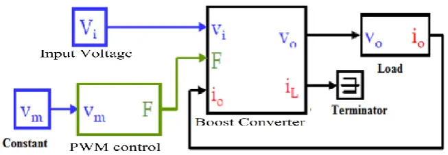
The complete converter circuit is shown in Figure 8
Figure 8: Open-loop Boost block diagram
Figure 8 is the circuit which has to be compensated for transients. Hence, the circuit is simulated to obtain the output voltage waveform. This waveform is divided into two parts, namely – Rise period and transient period. The transients are removed by applying the discrete output voltage waveform to the pattern recognition tool to remove the out of range transient voltages (keeping the rise time) and the output thus obtained is a transient free waveform.
Parameters of Neural Network:
No. of input data: 4 (input voltage, error, output voltage and reference voltage) Number of input neurons: 4
Number of hidden layers: 20 Number of output neuron: 1
III.SIMULATION RESULTS
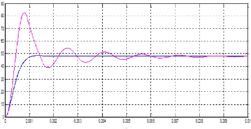
For Vin = 24V, L = 72 μH; C = 217 μF; R = 10Ω and Vref = 48V
4 Figure 9: ANN output = 0.96 and PI output = 0.55
Figure 10: Duty cycle for ANN and PI controllers
Figure 11: Output voltage waveform for ANN and PI controllers
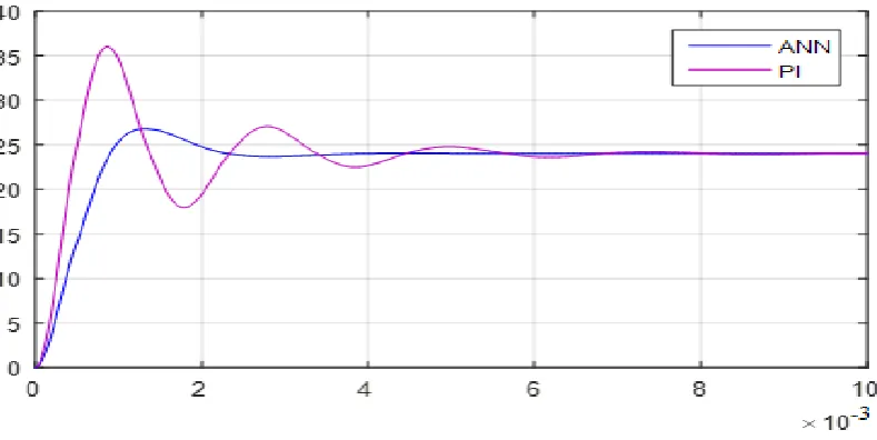
5 For Vin = 12V, L = 250μH; C = 50μF; R = 10Ω and Vref = 24V
Figure 12: ANN output = 0.9and PI output = 0.66
Figure 13: Output voltage waveform for ANN and PI controllers IV. CONCLUSION
A DC-DC converter transients have been removed using artificial neural network technique. The transients are at first segregated using pattern recognition tool and then compressed. Simulation results show that the proposed approach has almost completely removed all the transients. The proposed method also has a better response than that of a PI controller. The ANN based technique proves to be effective in decreasing overshoot, oscillations and settling time and also has a fast response in tracking the desired output voltage and is also. It is also observed that Levenberg-Marqueardt algorithm with 20 neuron structure gives better results than any other structure.
REFERENCES
[1] C. Batard, F. Poitiers, C. Millet and N. Ginot, Simulation of Power ConvertersUsing Matlab-Simulink
[2] B. S. Dhivya, V. Krishnan and R. Ramaprabha, “Neural Network Controller for Boost Converter” IEEE, March 2013[Circuits, Power and Computing Technologies (ICCPCT), 2013 International Conference on20-21]
[3] K. Sundareswaran , V.Devi, S. Sankar, S. Nayak and S. Peddapati,“Feedback controller design for a boost converter through evolutionary algorithms”, IET, 7, I 4, 903–913, 2014.