Copyright © The Author(s). 2014. All Rights Reserved. American Research Institute for Policy Development 42 Monticello Street, New York, NY 12701, USA. Phone: 1.347.757.4901 Website: www.aripd.org/jea
A Vertical Axis Wind Turbine and Its Control
Camilo Martinez1 & Cris Koutsougeras2
Abstract
This paper presents a study of a vertical axis wind turbine and its specific control. The specific structure of the turbine involves panels that must be perpetually flipped between a vertical position and a horizontal position so that each panel is vertical when it travels downwind and horizontal when it travels upwind. The flipping of each panel cannot be instantaneous and thus a need exists to determine a proper timing for accomplishing the change of the orientation of each panel so as to minimize energy losses. The contribution of this study is a method to determine the control for flipping the panels to maximize the energy production based on computational simulations.
Keywords: Wind turbine, airfoil control, airfoil simulation, energy optimization
Introduction
The designs of classic wind turbines that use blades arranged in the form of a propeller and base their operation on the Bernoulli effect, need to balance between the effects of forces causing the rotation and the drag that tends to slow down the rotation. Airfoils used for wind energy harvesting which are designed to deflect wind and thus make use of forces that are due to changes in the momentum of the air mass, might have an advantage although the standards for comparisons would have to be determined. For example, what dimensions of each kind -of classic or vertical axis type- would be considered as comparable. Nevertheless, the first step is the construction of a model and its study.
1
Dpt. of Computer Science & Industrial Technology, Southeastern Louisiana University, Hammond LA 70402, USA
2
The model selected for the purposes of this study is described below -and shown in Fig. 1- as a vertical axis structure with four panels arranged in symmetric pairs and with each panel controlled to be vertical during its downwind travel (thus producing energy to be harvested) and horizontal during its upwind travel (when it is producing drag). The transition from one orientation to the other cannot be instantaneous and it will be completed over a short period of time while the panel still follows part of its trajectory. This necessarily results in the panel leaving its energy producing phase before its theoretical optimal position (where this phase is completely exhausted) and entering its horizontal state of minimum drag later than the theoretical optimum position. The main purpose of this study is to provide a method for determining an appropriate schedule for accomplishing the flip of a panel so that the energy loss is minimized. The study is based on experimentation with computer simulations of the structure.
The Vertical Axis Turbine Structure
The structure considered here consists of wind-catching panels attached to a vertical main shaft which rotates and drives any attached energy harvesting apparatus (gears, generators etc) as shown in Fig. 1 below.
These panels are arranged in symmetric pairs relative to the vertical axis but they are to be maintained orthogonal in orientation so that one is vertical and the other panel of the pair is horizontal. The panel that is vertical will be catching the wind and will be pushed by the (deflected) wind while the one on the other side will only expose its edge to the wind thus encountering a minimal push from the wind. This will cause the structure to rotate until the vertical panel is in the downwind direction with respect to the main vertical shaft of the structure. At that point the orientations of both panels in that pair should flip so that now the one that is upwind from the shaft is vertical and the one that is in the downwind direction is horizontal. Additional pairs can be used in a stacked structure, mounted on the same vertical shaft. It should be easy to see that the key to sustained rotation is the ability to flip the orientations of the pairs of panels once a pair is at the position where they are aligned with the wind direction.
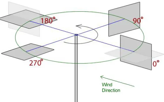
For purposes of reference, consider the trajectory of a single panel; it will be a circle in a horizontal plane as shown in Fig. 2. In this horizontal plane, the position of the panel that is upwind from the vertical shaft (with respect to the wind direction) is marked as 0o, and the corresponding one in the downwind position is marked as 180o. Ideally, the panel should be flipped in its vertical orientation exactly at the 0o position, remain vertical while traveling from 0o to 180o, flipped in its horizontal orientation at the 180o position, and remain in its horizontal orientation while traveling from the 180o position until it reaches the 0o position (when it should be flipped back to its vertical orientation again). Obviously, while traveling from the 0o to 180o positions (we will refer to this travel as the downwind leg) the panel contributes positively to the turbine's rotation thereby producing work to be harvested as energy, and while traveling from the 180o back to the 0o positions (we will refer to this travel as the upwind leg) the panel only contributes to the overall drag.
Flipping a panel however, cannot happen instantaneously, and it would not make sense to stop the motion until the panels are flipped. So a panel must be flipped while the whole wind turbine structure continues its turning motion (in the horizontal plane). If the turning continues while a panel is flipped, then some of the flipping process will have to be started towards the end of the downwind leg and possibly be completed in the beginning of the upwind leg. Some energy is bound to be lost either because the panel will not be fully deployed in the end of the downwind leg (so it will not be catching as much of the wind flux as it should) or because it will not be at its horizontal (minimal resistance) position in the beginning of the upwind leg. It should also be evident that the panel produces its maximum torque (and thus should be most effective) at its 90o position. From the 90o position its effectiveness drops as it reaches its 180o position. The considerations for flipping of the panel at the 0o position are similar. The various orientations that the panel assumes during the process of flipping it do not constitute a symmetric sequence of orientations.
This means that the time the flipping takes during the downwind leg implies losses of potentially harvested energy which has to be balanced against the time it takes for it to be completed in the upwind leg when the panel's drag is not minimal (as when it finally assumes its horizontal orientation). It would seem that a solution is to just flip it as fast as possible but this would increase the power needed for the mechanism that does the flip as well as to overcome the air resistance to the flip itself given that each panel is expected to be quite large. Therefore the question is, what are the optimal positions to start and end the flip given that it can be performed with a certain fixed speed (and not instantaneously). Further, it is assumed that each panel can be flipped independently of the others, so a panel can be studied independently of the others. The problem is to determine the flipping schedule relative to the wind direction, so even when the wind direction changes the method would adapt to the new wind direction, thus the mechanism for driving the flip is also assumed to be equipped with a sensor for the wind direction.
Understanding the Air Flow
Figure 3: FoilSim showing air flow around a pole
Nevertheless, FoilSim provides some important information about the movement of the wind around an airfoil and allows a fairly good estimation of airflow parameters. Since graphic plots are obtained, a means for estimating the magnitude of the wind force from the graphic plot had to be used. The selected means was an angle representing the rate of separation of the plotted graphic lines in front of the panel. Based on these simulations and using AutoCad, the angles for optimal positions were determined.
Fig. 4 was obtained by using the FoilSim simulation. The Fig. 4 corresponds to that of Fig. 2 but with the positions of minimal observed drag shown. This allows to determine the angle when the wind will start producing significant drag on the panel and the angle when the drag becomes very low. For example, one position is shown as ang1 (20 degrees) and its corresponding drag is represented by an angle measure shown as ang3.
Figure 4: Calculating angles based on FoilSim simulation.
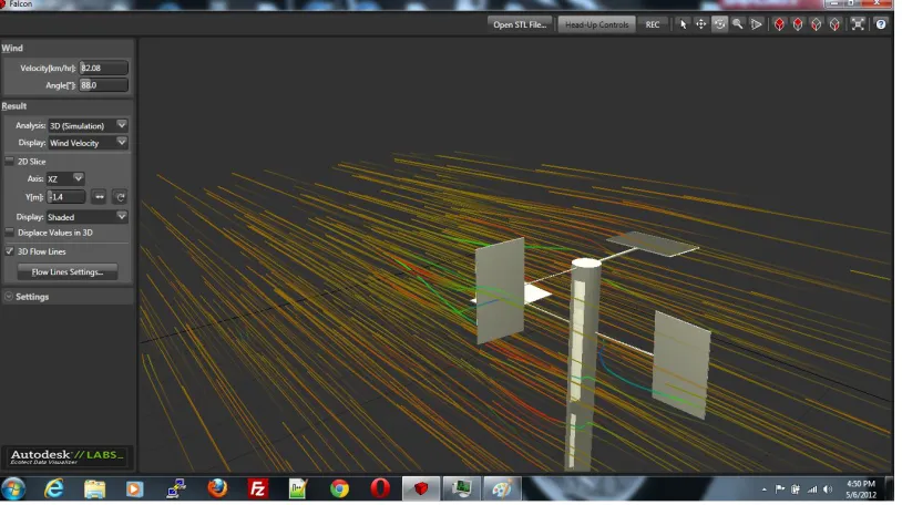
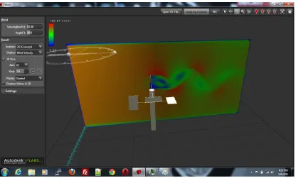
The model for the Falcon was produced as follows: The turbine was designed in Google SketchUp (this was the actual model that is shown in Fig.1) and then the model was exported to AutoCAD Inventor to generate an STL file that was then used in AutoCAD Falcon, a simulation software for wind tunnels. The following screen shots (Fig. 5 through 8) illustrate the experiments.
It should be noted that the speed and wind direction was kept constant during the course of an experiment. However, this is not a limitation given that the mechanism that drives the flipping is assumed to be able to sense the wind direction and thus adjust to such directional changes (but this assumes slow enough changes and not wind shear conditions).
Figure 5: Wind flow through the whole system
Figure 7: Wind resistance when panel is up on 0 degrees.
With the above simulation and calculations, it was determined that the start angle for flipping the panel up should be approximately 350° and be completed around the 8° position. Respectively, the panel should start being flipped to the horizontal at approximately 160° and be completed by the 180° position.
The maximum efficiency of the panel is between the 20° position and the 160° position. The minimal drag is a 15° arc around the 0° position.
Conclusion
Experimental methods based on simulation tools, rather than analytic means, was used to determine the operating parameters of a specific wind turbine with panels alternating in vertical and horizontal orientations. The use of FoilSim and AutoDesk Falcon was illustrated as a method to determine the best positions to adjust the panel orientations. It is conceivable that the method may be used for studying other and different types of airfoils.
References
1. NASA FoilSim. http://www.grc.nasa.gov/WWW/k-12/airplane/foil3.html 2. Project Falcon http://labs.autodesk.com/utilities/falcon