Please cite this article as: M. D. Manshadi, A. R. Mostofizadeh, M. A. Jozvaziri, Parametric Study of Movement Path in Two-dimensional Wing Flow Separation: Experimental Investigation, International Journal of Engineering (IJE), TRANSACTIONS C: Aspects Vol. 30, No. 9, (September 2017) 1401-1407
International Journal of Engineering
J o u r n a l H o m e p a g e : w w w . i j e . i rParametric Study of Movement Path in Two-dimensional Wing Flow Separation:
Experimental Investigation
M. D. Manshadi*, A. R. Mostofizadeh, M. A. Jozvaziri
Department of Mechanical and Aerospace, Malek Ashtar University of Technology, Isfahan, Iran
P A P E R I N F O
Paper history:
Received 23 April 2017
Received in revised form 04 July 2017 Accepted 07 July 2017
Keywords: Experimental Data Cargo Separation Air Foil
A B S T R A C T
The aim of this experimental study is two-dimensional investigation of cargo behavior after separation which is carried out in the subsonic wind tunnel. Given that the real separation occurs in three-dimension, the results of this study may be widely used in numerical aerodynamic studies for verification of new computational methods and they can be used as the reference results in this area. So a mechanism has been used which is simulated in two-dimensional physic with three degrees of freedom (x, y, θ) in the subsonic wind tunnel. A wing with NACA0012 airfoil as well as two circular disks at both ends (to simulate two-dimensional flow) have been utilized and separated from the upper surface of the test chamber. For parametric study, the tests have been experimented in the initial attack angles of -10 to +10 degrees with step of 5 degrees at velocity of 15 m/s and at velocities of 10, 15 and 20 m/s at zero degree initial angle of attack. Each test has been repeated 3 times and if there were any differences in the results, the number of repetitions have been increased. To extract the result, several cameras have been installed around the test chamber which take pictures with high-speed shooting. Then, using image processing techniques, x, y, and θ diagrams have been extracted over the time.
doi: 10.5829/ije.2017.30.09c.13
NOMENCLATURE
a Acceleration ( m/s2) I Moment of inertia (kg.m)
D Drag force (N) L Lift force (N)
F Force (N) m Mass (kg)
Fk Kinetic frictional force (N) M Moment (N.m)
g Gravity acceleration ( m/s2) X , Y and Z Directions of coordinate system
1. INTRODUCTION1
One of the needs of aerodynamic designers and engineers has always been wind tunnel or flight testing experimental tests to validate and ensure analysis. Due to the high cost and risks involved in flight testing, the wind tunnel tests are quite important [1]. The implementation of the wind tunnel results with flight testing is one of the major challenges in this area.
In a separation phenomenon, the design and analysis need to be verified, due to the complexity of dynamic and aerodynamic. There are various methods to analyze
*Corresponding Author’s Email: [email protected] (M. D. Manshadi)
researches have been done in this area which are generally three-dimensional but because of military applications, the results have not been published as detailed [3]. Therefore accurate presentation of results and test conditions are very important for numerical aerodynamic researchers.
There are various methods and mechanisms for dynamic tests in wind tunnel. These mechanisms have lots of variety generally in roll and pitch and are improving day by day [4, 5]. But for separation phenomenon testing, usually Captive Trajectory System (CTS) is used. In this method, the separated object is kept beside the main object (e.g. fighter jet) and six components of force and torque are calculated on it. Then according to the six components, dynamic condition of the model, time step and the new position of the object are calculated by the computer and the moving holder transfer it to the new position [6]. Figure 1 shows a picture of CTS that is related to bomb separation testing from F-35 fighter jet which was carried in transition wind tunnel of Arnold Engineering Development Complex (AEDC) [7].
One of the standard models in store separation used by CFD researchers is a store/pylon model that separates from a delta wing [8]. The results of this study have been used as as a reference result in many researches.
Other researches with military applications have been done experimentally in store separation like Joint Direct Attack Munition (JDAM) separation from F/A18-C fighter jet in transonic regime [9] or Hyper-X stage separation in supersonic wind tunnel [10].All tests have been conducted using CTS. Other methods used to perform separation tests are commonly applied in subsonic regimes.
Figure 1.Bomb separation testing of F-35 fighter jet by CTS
[7]
Here, the store separates from the main object, moves freely and at the end of the test stops by the fence [11].
As mentioned, all the studies have been conducted in 3D space (6 degrees of freedom) and there is no reference result from store separation in two-dimensional space. While, 2D results are very important for CFD researchers and they use them for validation of new numerical methods. Therefore one of the aim of this study is to present the reference results of store separation in 2D space.
2. TESTS DESCRIPTION
In this study, a NACA0012 airfoil separation is simulated from a flat plate (upper wall of wind tunnel test chamber) in 2D space. For this purpose, two electromagnets fixed the model in the initial condition while the wind tunnel reaches to desired speed. Then after cutting off the electricity, the model separates and the test begins. According to 2D physic, the store has 3 degrees of freedom (3DOF) and can move freely on mounted rails in X and Z directions and rotate around Z axis. The movements have been limited at the bottom by some limiters and springs and the test ends. The test progress has been photographed by the high frequency cameras and images have been processed. So the X, Y and θ charts have been graphed over the time.
To investigate the effects of initial angle of attack, the case has been tested at velocity of 15 m/s and at initial angles of attack of -10 to 10 degrees with steps of 5 degrees. For this purpose, there are adjusted screws at the two ends of the wings that allow adjustment of the initial angle of attack. After adjusting and checking the initial angle of attack by a precision angle gauge, the adjusting screws are tightened and wings are fixed in the position.
To evaluate the effects of airflow velocity, the case has been tested at zero initial angle of attack and velocity of 10, 15 and 20 m/s. For this purpose, the air velocity is adjustable and fixed at the desired speed by increasing and decreasing of the wind tunnel electro fan. Each test has been repeated 3 times and in case of noncompliance, the number of repetitions have been increased up to 7 times. The initial distance of airfoil up to upper wall of the test chamber is set to 15 cm. The ambient pressure and temperature are 85400 Pa and 18 ºC, respectively.
3. TEST EQUIPMENT
3. 1.Wind Tunnel A low-speed wind tunnel (0 to 100 meters per second) is used with a test chamber dimensions of 100×80×160 cm which is located in Qadr research center – University of Imam Hossein. Table 1 describes wind tunnel characteristics.
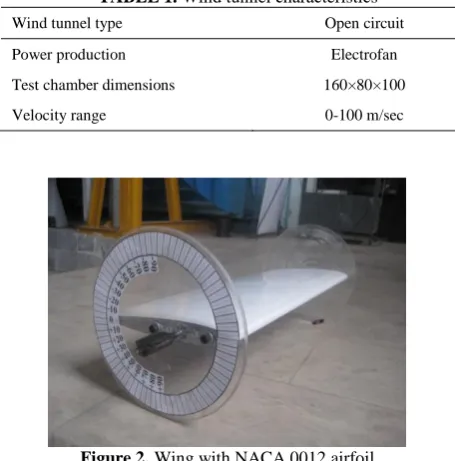
3. 2. Separated Wing A wing with NACA0012 airfoil has been used as a separated store. To create two-dimensional flow, a constant wing at spin direction is used (no taper ratio, no sweep angle nor twist angle) and two disks are located at both ends of the wing to prevent 3D effects at wingtips. Figure 2 shows the mentioned wing and Table 2 indicates wing specifications.
3. 3. 2D Physics Simulator Mechanism To simulate 2D physic with 3 DOF, a new mechanism has been applied which has high safety and low cost. Firstly the mechanism fixes the store beside the main object until the wind tunnel reaches to the target velocity.
TABLE 1. Wind tunnel characteristics
Wind tunnel type Open circuit
Power production Electrofan
Test chamber dimensions 160×80×100
Velocity range 0-100 m/sec
Figure 2.Wing with NACA 0012 airfoil
TABLE 2. Wing specifications
Airfoil model NACA0012
Chord length 25 cm
Span length 60 cm
Axis of rotation 6 cm from the leading edge
Material Composite
Weight 2430 g
Moment of inertia 3.7 g.m
Secondly the store separates and it can freely moves in 3 DOF in 2D physic on mounted rails. 3 DOF of store includes horizontal movement along X axis, vertical movement along Y axis and twisting motion around Z axis [3]. The schematic view of the mechanism is shown in Figure 3.
3. 4. Extracted Results
Desired results in this study are airfoil position (x, y, θ) over the time. For this purpose, there are various methods [12] that due to cost effectiveness and for increasing the accuracy photography is used [13]. A high frequency camera is used with shooting of 1200 frames per second and the behavior of the store is recorded by it. Then the pictures separated frame by frame and image processing has been done on each frame and finally the final results have been obtained.
4. TEST RESULTS
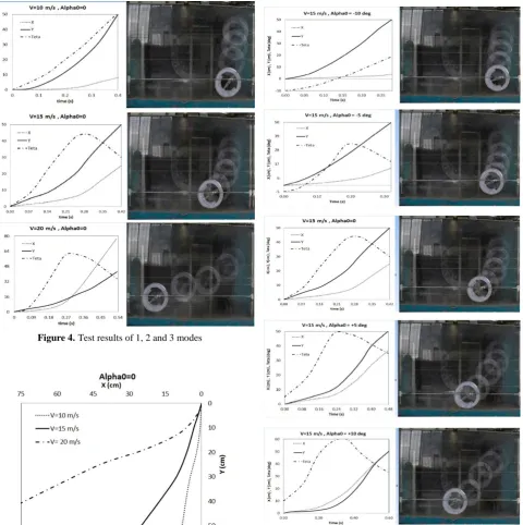
To investigate the effects of the initial angle of attack and free flow velocity, 7 modes have been tested totally and the characteristics of the modes have been shown in Table 3. The tests have been repeated for at least three times and maximum 7 times for each mode to ensure the repeatability. So more than 30 dynamic tests have been experimented in the subsonic wind tunnel. Figure 4 shows the test results of 1, 2 and 3 modes.
Figure 3. Schematic view of the mechanism in 3 DOF [3]
TABLE 3. Tests modes characteristics
Number of repetition Initial angle of
attack (degree) Free flow
velocity (m/s) Modes
3 0
10 1
4 0
15 2
5 0
20 3
5 -10
15 4
4 -5
15 5
3 +5
15 6
7 +10
The initial angles of attack have been set zero degree and the freestream velocity has been considered as a variable at the three modes. So the effects of freestream velocity can be investigated by comparison of the graphs. According to Figure 4, by increasing the air velocity the drag force is increased and the wing travels more horizontally. This behaviour is well seen in Figure 5. Figure 5 compares the path of movement (X over Y) in three different modes for better understanding.
Figure 6 shows the test results of 1, 4, 5, 6 and 7 modes.
Figure 4.Test results of 1, 2 and 3 modes
Figure 5.The effect of free stream velocity on path movement
In these situations the freestream velocity has been set constant (15 m/s) and the angle of attack is variable. So the effects of initial angle of attack can be investigated similarly. Figure 7 compares the path of movement (X over Y) in five different modes for better understanding.
5. ERRORS ANALYSIS
One of the most important parameters in a wind tunnel tests is a compliance testing condition (geometry, dynamics and aerodynamic) with real state.
Figure 7. The effect of initial angles of attack on path movement
By using this mechanism, some differences between real state and testing condition occurred which caused errors in the results. The most important differences are: 1- In real state, the twisting motion around the axis that is attended in the test may not be considered.
2- In the test state, the weight and inertia moment of mechanism parts affect the behavior of airfoil.
3- In the test state, the friction between the mechanism part affect the behavior of airfoil.
Given that the 2D separation does not exist in practice and the purpose of this test is a criterion for validation of numerical codes, the errors can be easily considered in the calculations. To fix the first error, the torque should be calculated around the test point (a quarter of the chord) and the body should be moved around the same spot. To modify the second error, it’s easy to apply the weight and inertia moment of effective parts on the formulation. The modified motion equations are shown in Equations (1) to (3):
∑ 𝑀𝑧= 𝛼𝑧∑ 𝐼𝑧 ⟹ 𝑀𝑎𝑒𝑟𝑜= 𝛼𝑧 × ( 𝐼𝑤𝑖𝑛𝑔+
𝐼twisting rail ) (1)
∑ 𝐹𝑥= 𝑎𝑥∑ 𝑚𝑥 ⟹ 𝐷 = 𝑎𝑥 × ( 𝑚𝑤𝑖𝑛𝑔+
𝑚twisting rail) (2)
∑ 𝐹𝑦= 𝑎𝑦∑ 𝑚𝑦⟹ 𝐿 − (𝑚𝑤𝑖𝑛𝑔+ 𝑚twist rail+
𝑚horizontal rails) = 𝑎𝑦× (𝑚𝑤𝑖𝑛𝑔+ 𝑚twisting rail+
𝑚horizontal rails)
(3)
To solve the third error the friction can be calculated and applied on the formulations [3]. Further, equations with fractional force corrections are shown in Equations (4) to (6):
∑ 𝑀𝑧= 𝑀𝑎𝑒𝑟𝑜− 𝑀𝑘𝑡𝑤𝑖𝑠𝑡𝑖𝑛𝑔 (4)
∑ 𝐹𝑥= 𝐷 − 𝐹𝑘ℎ𝑜𝑟𝑖𝑧𝑜𝑛𝑡𝑎𝑙 (5)
∑ 𝐹𝑦= 𝐿 − ( 𝑚𝑤𝑖𝑛𝑔+ 𝑚twisting rail+ 𝑚horizontal rails )𝑔 −
𝐹𝑘vertical
(6)
Table 4 shows the needed parameters for modifications on formulations.
TABLE 4. The needed parameters for modification on
formulation
0.04 (g.m) Inertia moment of twisting rail
366 (g) The weight of twisting rails
3148 (g) The weight of horizontal rails
0.11 Friction coefficient of twisting
0.18 Linear friction coefficient in horizontal movement
0.14 Linear friction coefficient in vertical movement
6. CONCLUSION
The aim of this study is the presentation of reference results in the store separation field on 2D and subsonic regime. Considering the new proposed method by the CFD researchers for solving the moving problems, initially proposed as a 2D and then extends to 3D, the experimental results in 2D mode are very important. Thus the presented results in this study are very popular for the CFD researchers. Also for better use, all the information about geometric, dynamic and aerodynamic detail have been given.
In this study the effect of freestream has also been studied experimentally. Due to symmetric geometry of airfoil and initial angle of attack of 0 degrees, there is no lift and the wing falls under gravity. In the fall of the store, the vertical velocity component is applied to the wing and the angle of attack is set proportional to tan
-1(V∞/h). The angle of attack causes the rotational
motion in wing and the angle of attack increases. The rotational motion makes the lift force unlike the gravity force. Therefore the decline of the wing decreases.
Given that the lift force is increased by the square of velocity, at higher velocities the rate of fall decreases that the obtained results approve it.
In addition, the effect of initial angle of attack is studied. In non-zero angle of attack the drag force is more and the moving on the horizontal axis (X) increases. Also on the negative angle of attack, the lift force is in direction of weight that increases the rate of fall and on positive angle of attack, the lift force is unlike the weight and decreases the rate of fall. The obtained results confirmed this.
7. FUTURE RESEARCH
The effects of other parameters can be investigated by using the mechanism. The parameters include:
- The initail distance of the airfoil up to the upper surface of the test chamber.
- Changing the airfoil’s rotational axis (in chord direction).
- Investigation of the ejector effect at the test start. - The geometry changing of the upper surface
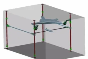
Figure 8. A schematic view of experiment in 3D mode
The 3D separation can be also simulated with a little erorr by few changes in the mechanism. For this purpose, a three-dimensional object should be used as the main object in wind tunnel and the 3D cargo should be installed on the torsional rail. A schematic view of this situation has been shown in Figure 8 [3]. The reference results in 3D mode can be presented by consideration of the mentioned changes.
8. ACKNOWLEDGMENTS
The authors appreciate Najm and Qadr research centers staffs, Dr Ghadak and Dr. Haghiri for their support and they thank all the colleagues who have helped the authours in doing this research, especially Mr. Kalantary, Mr. Dorosty for testing and Mrs Eftekhari for image processing.
9. REFERENCES
1. Cenko, A., "Store separation lessons learned during the last 30 years" (2010), Naval Air Systems Command Patuxent River Md.
2. Jafari, M., Toloei, A., Ghasemlu, S. and Parhizkar, H., "Simulation of store separation using low-cost cfd with dynamic meshing", International Journal of Engineering-Transactions B: Applications, Vol. 27, No. 5, (2013), 775-783.
3. Manshadi, M., Mostofizade, A. and Vaziri, M., "Experimental set-up for 2d cargo release test in subsonic wind tunnel",
Arabian Journal for Science and Engineering, Vol. 42, No. 5, (2017), 2157-2166.
4. Zhengzhou, R., Wenshan, Y. and Yongyi, M., "Control system of double-roll mechanism of 2.4 m transonic wind tunnel [j]",
Ordnance Industry Automation, Vol. 10, (2011), 25-34. 5. Chen, P., Liu, C. and Zhang, J., "Research and design of a novel
pitch mechanism for supersonic wind tunnel", Arabian Journal for Science & Engineering (Springer Science & Business Media BV), Vol. 39, No. 8, (2014).
6. Carman Jr, J., Hill Jr, D. and Christopher, J., "Store separation testing techniques at the arnold engineering development center. Volume 2. Description of captive trajectory store separation testing in the aerodynamic wind tunnel (4t)". 1980, Aro Inc Arnold AFS TN.
7. D., O., "Arnold test teams prepped f-35 for first external weapons release", Arnold Engineering Development Complex Public Affairs, U.S. AIR FORCE., (2015).
8. Heim, E., "CFD wing/pylon/finned store mutual interference wind tunnel experiment". (1991), Arnold Engineering Development Center Arnold AFS TN.
9. Cenko, A., "F-18c/jdam cfd challenge wind tunnel and flight test results", AIAA Paper, (1999), 99-0120.
10. Woods, W.C., Holland, S.D. and DiFulvio, M., "Hyper-x stage separation wind-tunnel test program", Journal of Spacecraft and Rockets, Vol. 38, No. 6, (2001), 811-819.
11. Chambers, J., "Modeling flight nasa latest version: The role of dynamically scale free flight models in support of nasa aerospace programs, Joseph Chambers, Vol. 3, (2015). 12. Manshadi, M.D., Vahdat-Nejad, H., Kazemi-Esfeh, M. and
Alavi, M., "Speed detection in wind-tunnels by processing schlieren images (research note)", International Journal of Engineering-Transactions A: Basics, Vol. 29, No. 7, (2016), 962.
Parametric Study of Movement Path in Two-dimensional Wing Flow Separation:
Experimental Investigation
M. D. Manshadi, A. R. Mostofizadeh, M. A. Jozvaziri
Department of Mechanical and Aerospace, Malek Ashtar University of Technology, Isfahan, Iran
P A P E R I N F O
Paper history:
Received 23 April 2017
Received in revised form 04 July 2017 Accepted 07 July 2017
Keywords: Experimental Data Cargo Separation Air Foil
ديكچ ه
رد اب .تسا هتفریذپ تروص داب لنوت کی رد و یدعب ود تروص هب هک تسا هلومحم کی شیادج یسررب هعلاطم نیا زا فده
نیا نتفرگ رظن هس تروص هب هلومحم شیادج هک هتکن
یم تروص یدعب یم هعلاطم نیا زا لصاح جیاتن ،دریذپ
هب دناوت روط
ود مزیناکم کی زا روظنم نیمه هب .دریگ رارق عجرم ناونع هب و دیدج یددع جیاتن یجنس تحص تهج یعیسو تهج یدعب
هیبش هس اب کیزیف یزاس ( یدازآ هجرد
x, y, θ
)
نودام داب لنوت رد لیوفریا اب لاب کی .تسا هدش هدافتسا توص
NACA0012
هیبش ببس هب( لاب یاهتنا ود رد راود کسید ود هارمه هب و تسا هتفرگ رارق هدافتسا دروم )یدعبود یزاس
شیامزآ ،کیرتماراپ یسررب روظنم هب .تسا هدیدرگ ازجم تست هظفحم ییلااب حطسزا هیلوا هلمح یایاواز رد اه
10 و 10 اب +
گ ینامز ما 5 تعرس رد هجرد 15
تعرس رد نینچمه و هیناثرب رتم یاه
10 ، 15 و 20 هجرد رفص هیلوا هلمح هیواز و هیناثرب رتم
نومزآ ره .تسا هتفریذپ تروص 3
یم شیازفا اهرارکت دادعت ،دش هدهاشم جیاتن رد یتوافت رگا و تسا هدش رارکت راب .تفای
اب سپس .تسا هدش هدافتسا نومزآ هظفحم فارطا رد لااب یرادرب ریوصت تعرس اب نیبرود یدادعت زا جیاتن جارختسا تهج
یاهرادومن ریوصت شزادرپ زا هدافتسا
x
و
y
و
θ
.تسا هدش مسر نامز هب تبسن
![Figure 1. Bomb separation testing of F-35 fighter jet by CTS [7]](https://thumb-us.123doks.com/thumbv2/123dok_us/206049.2014921/2.595.96.248.521.721/figure-bomb-separation-testing-f-fighter-jet-cts.webp)