A CLOSED FORM SOLUTION FOR FREE VIBRATION
ANALYSIS OF TUBE-IN-TUBE SYSTEMS IN TALL BUILDINGS
M. Malekinejad
Department of Civil Engineering, Shahid Bahonar University of Kerman, Kerman, Iran Malekinejad.Mohsen@gmail.com,
R. Rahgozar*
Rahgozar@mail.uk.ac.ir *Corresponding Author
(Received: January 24, 2011 – Accepted in Revised Form: December 15, 2011) doi:10.5829/idosi.ije.2012.25.02a.01
Abstract In this paper the dynamic response of tube-in-tube systems for tall building structures is investigated. Inner and outer tubes are modeled using equivalent continuous orthotropic membranes; in which, each tube is individually modeled by a cantilever box beam. By applying the compatibility conditions on deformation of the two tubes, the governing dynamic equations of the tube-in-tube structure and their associated boundary conditions are derived using the variational principle of virtual work. Appling differential calculus with some simplifications, and deriving non-trivial solution of these equations, a closed form solution is presented to obtain natural frequency and mode shape of tube-in-tube structures. A quick estimate of these quantities is of particular importance at the early stages of tube-in-tube systems design prior to a full dynamic analysis. In order to illustrate the efficiency of the proposed model a symmetrical building is analyzed and comparisons are made with more accurate results obtained by three dimensional computer dynamic analysis and previous published methods.
Keywords Tall buildings; Tube-in-tube; Free vibration; Variational principle; Natural frequency; Mode Shape.
هﺪﯿﮑﭼ
رد اﯾ د ﺦﺳﺎﭘ ﻪﻟﺎﻘﻣ ﻦ ﯾ
ﻣﺎﻨ ﯿ ﺳ ﯽﮑ ﯿ ﺤﻣ بﺎﻗ ﻢﺘﺴ ﯿ
ﺮﺑ درﻮﻣ ﺪﻨﻠﺑ يﺎﻬﻧﺎﻤﺘﺧﺎﺳ رد ﻮﺗ رد ﻮﺗ ﯽﻄ راﺮﻗ ﯽﺳر
ﺖﺳا ﻪﺘﻓﺮﮔ .
بﺎﻗ ﭘوﺮﺗﻮﺗروا تﺎﺤﻔﺻ زا هدﺎﻔﺘﺳا ﺎﺑ ﯽﺟرﺎﺧ و ﯽﻠﺧاد يﺎﻫ ﯿ
ﭘ ﮏ ﯿ لدﺎﻌﻣ ﻪﺘﺳﻮ هﺪﺷ يزﺎﺳ
رد ﻪﮐ ﺪﻧا
ﺎﺑ ﻪﻧﺎﮔاﺪﺟ رﻮﻃ ﻪﺑ بﺎﻗ ﺮﻫ نآ ﯾ
ﺗ ﮏ ﯿ هﺮﻃ ﺮ يا ﺎﺟ ﯾ ﺰﮕ ﯾ ﺖﺳا هﺪﺷ ﻦ .
ﻐﺗ يرﺎﮔزﺎﺳ ﻦﺘﻓﺮﮔ ﺮﻈﻧ رد ﺎﺑ ﯿﯿ
ﺮ ﻞﮑﺷ يﺎﻫ
و ﯽﺟرﺎﺧ و ﯽﻠﺧاد بﺎﻗ ود ﻪﺑ
ﮔرﺎﮐ ﯿ ﻐﺗ بﺎﺴﺣ لﻮﺻا يﺮ ﯿﯿ
و تاﺮ و هزﺎﺳ ﺖﮐﺮﺣ ﺮﺑ ﻢﮐﺎﺣ تﻻدﺎﻌﻣ يزﺎﺠﻣ رﺎﮐ
ﺒﻃ ﺲﻧﺎﮐﺮﻓ ﺮﺑ ﻢﮐﺎﺣ تﻻدﺎﻌﻣ ﯿ
ﺖﺳا هﺪﺷ ﻞﺻﺎﺣ ﺮﻇﺎﻨﺘﻣ ﻞﮑﺷ دﻮﻣ و ﯽﻌ .
ﻤﺨﺗ ﯿ ا ﻦ ﯾ رد ﯽﺷﺎﻌﺗرا تﺎﺼﺨﺸﻣ ﻦ
ﻟﺎﻧآ ﯿ ﻟوا ﺰ ﯿ ﺳ ﻪ ﯿ ﺤﻣ بﺎﻗ ﻢﺘﺴ ﯿ
رد ﻮﺗ ﯽﻄ ﻟوا دروآﺮﺑ و ﻮﺗ
ﯿ ﻔﻣ ﻪ ﯿ ﯽﻣ ﺪ ﺪﺷﺎﺑ . ارﺎﮐ و ﺖﺤﺻ ﯾ
ﺎﺘﻧ ﯽ ﯾ شور زا ﻪﻠﺻﺎﺣ ﺞ
ﭘﯿ ﺳ ﺎﺑ يﺪﻨﻠﺑ نﺎﻤﺘﺧﺎﺳ ياﺮﺑ يدﺎﻬﻨﺸ ﯿ
ﺤﻣ بﺎﻗ ﻢﺘﺴ ﯿ
ﻟﺎﻧآ ﻮﺗ رد ﻮﺗ ﯽﻄ ﯿ
ﺎﺘﻧ و ﺰ ﯾ ﻟﺎﻧآ ﺎﺑ ﻪﻠﺻﺎﺣ ﺞ ﯿ
ﭙﻣﺎﮐ ﺰ ﯿ ﺎﺘﻧ و يﺮﺗﻮ ﯾ
ﺞ
شور زا ﻪﻠﺻﺎﺣ ﺎﻘﻣ دﻮﺟﻮﻣ ﯽﻠﺒﻗ يﺎﻫ
ﯾ ﻪﺴ هﺪﺷ ﺖﺳا .
Nomenclature
A Sum of the cross sectional area of exterior columns Ci Arbitrary coefficients of general solution
dc Dimension of column
E Modulus of elasticity
EI Flexural rigidity of a tall building
G Shear modulus
h Height of story
H Total height of the building
j An integer representing mode number
P(x,t) Distributed external force
sf Span spaces of flange frame
sw Span spaces of web frame
S Shear rigidity of a tall building
t Thickness of equivalent membrane
u Natural mode shape function
2Wf Width of flange frame
2Ww Width of web frame
Wext Virtual work done by external forces
x Spatial position of any material along the height of the building y(x,t) Lateral displacement of the building
Variation operator
Poisson ratio
Mass density
Circular natural frequency
Nondimensional coordinate for xﻮﺗ رد ﻮﺗ ﯽﻄﯿﺤﻣ بﺎﻗ ﻢﺘﺴﯿﺳ دازآ شﺎﻌﺗرا ﺮﺑ ﺎﻫيزﺎﺳهدﺎﺳ ﯽﺧﺮﺑ لﺎﻤﻋا ﺎﺑ .ﺪﻧاهﺪﻣآ ﺖﺳﺪﺑ يزﺮﻣ ﻂﯾاﺮﺷ
1. INTRODUCTION
Tall building structures are affected by lateral loads due to wind or earthquake actions to an extent that they play an important role in structural design. Over the last decades, various forms of tall building structures have been developed to be efficient in resisting lateral loadings [1]. In general, framed tube structures are widely accepted as an economical system in high rise buildings, over a wide range of building heights. Framed tube system, in its simplest form consists of closely spaced exterior columns tied at each floor level by relatively deep spandrels [2]. In order to increase the efficiency of the framed tube under the lateral loads, framed tube commonly is utilized with central core. A framed tube under lateral loads acts like a cantilevered box beam to resist the overturning moment; and the central core acting like second tube within the outside tube. The central core may be designed not only for gravity load but also to resist lateral loads. When lateral sway is critical and starts controlling the design, the ‘‘framed tube’’ can be supplemented by a tube instead of the central core to create ‘‘tube-in-tube’’ system [1]. In recent years, due to developments in design technology and material qualities in civil engineering, the structures have become lighter and more slender. These will cause the structure to vibrate when they are located in environments where earthquake or high winds exist.
These vibrations may lead to serious structural damage with potential for structural failure. A great number of researches have studied the natural modes of tall buildings over the past decades. Youlin [3] has analyzed tube-in-tube structures. In this work, the outer framed tube was considered as an equivalent closed tube. Based on compatibility of deformation between the two tubes, a differential equation was developed and formulas for calculating horizontal displacements of tube-in-tube structure and load distribution on the two tubes were derived. Then, the natural period of the first mode of tube-in-tube structure and the seismic loads on it were obtained by the Top-Displacement method. Wang [4] obtained a formula for calculating the natural frequencies of tube-in-tube structures in tall buildings directly from the fourth-order Sturm-Liouville differential equations. In another study, numerical solutions of eigenvalues for free vibration of tube-in-tube structures by
using modified ODE solver for eigenvalue problem was presented by him based on an existing Ordinary Differential Equation (ODE) solver [5]. Lee [6] proposed a simple mathematical model for approximate analysis of framed tube structures with multiple internal tubes using the minimum potential energy principle in conjunction with the variational approach. Lee [7] presented an approximate solution that was formulated for free vibration analysis of tube-in-tube tall buildings. The governing partial differential equation of motion has been reduced to an ordinary differential equation with variable coefficients on the assumption that the transverse vibration is harmonic. A power-series solution was used to obtain mode shape functions for the tube-in-tube structures.
In the present study, a mathematical model is proposed for accurate prediction of the fundamental natural frequencies and corresponding mode shapes of tube-in-tube systems in tall building structures. Tube-in-tube system is analyzed using an orthotropic box beam analogy approach in which each tube is individually modeled by a box beam thus accounting for flexural as well as the shear deformations [6, 8-10]. Appling compatibility of deformation for the two tubes, the governing dynamic equations of the tube-in-tube structure and their associated boundary conditions are derived using variational principle of virtual work. Appling differential calculus with some simplifications, and deriving non-trivial solution of these equations, a closed form solution has been presented to obtain the fundamental natural frequencies and mode shapes of tube-in-tube structures. The method is simple and accurate enough. It can greatly reduce the computational work as compared to finite element approach, and yet a solution of acceptable precision can be obtained.
2. DERIVATION OF THE BOUNDARY AND EIGENVALUE PROBLEMS
vibration analysis, it also permits one to visualize directly the dynamic performance of tall building structures, and hence to understand qualitatively how the natural frequencies and corresponding mode shapes are related to the structural parameters by carrying out simple parametric studies. The analytical techniques based on continuum modeling can clearly reveal the static and dynamic characteristics of tall building structures. Moreover, information provided by the analytic technique, can also be used to develop a basis for analysis of tall building structures using approximate methods. Furthermore, to investigate the influence of particular structural parameters on static and dynamic characteristics of a given structure, it is very convenient if analytical methods are utilized. The advantages of both analytical and approximate methods based on continuum modeling for tall building structures are not realized by the highly time consuming modeling in finite element analyses. In contrast, the finite element approach requires one to solve thousands of linear simultaneous equations to obtain quantitative results in detail. So it is a powerful tool for analysis and design at the detailed and final design stages of tall buildings. It takes much more time hence expensive, for the modeling of a given structure using finite elements.
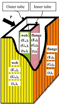
In this section an approximate mathematical model is presented to obtain natural frequencies and corresponding mode shapes of tube-in-tube structure can be modeled as an assemblage of equivalent orthotropic plate panels. Consequently, a framed-tube structure may be analyzed as a continuum. Figure 1 shows a typical framed-tube structure with internal tube. Each of the tubes is composed of four equivalent orthotropic plate panels. All framed tubes under consideration consist of an assemblage of such plate panels of uniform thickness in vertical planes [10]. Each framed tube structure can be modeled as cantilever beam with hollow section. Thus, the tube-in-tube model can represent a coupled system consisting of two tubes. Since floor slabs is essentially rigid within their own plane, the relative lateral displacements between the two tubes can be assumed negligible at each floor level. The outside tube and the internal tube, each described by a set of differential equations, are forced to have compatible lateral deflection at the floor level.
The following assumptions are adopted in this paper for structural analysis:
a) Structure's behavior is linear elastic.
b) Floor slabs are considered to be rigid diaphragms within their own plane.
c) The spacing of beams and columns are uniform through the building height.
d) Sectional properties for beams and columns are uniform throughout the height of building.
Analytical analysis for natural frequencies and corresponding mode shapes is carried out using the Hamilton’s principle. By considering a distributed system defined over the closed domains 0 x H, where x is the spatial position of any
material point of the system, H is total height of
the structure and lateral displacement of cantilevered beams are denoted by y(x,t) (see
Figure 2.Behavior of tube-in-tube structure.
Outer tube Inner tube
web flange
web
flange
(Ew)o
(Gw)o
tw)o
(
(Ef)o
(Gf)o
(tf)o
(Ew)i
(Gw)i
tW)i
(
(Ef)i
(Gf)i
(tf)i
P
X
+
Outer tube Inner tube
H
P
Figures 2 and 3).
Figure 1.Equivalent tube-in-tube structure.
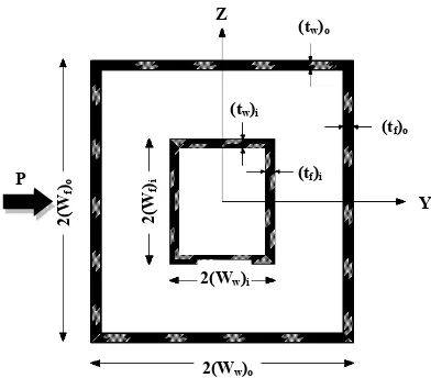
Figure 3.Structural plan of the tube-in-tube structure.
Hamilton’s principle [11-14] states that:
2 2 2 2
1 1 1 1
( ) 0
t t t t
ext ext
t L dt t W dt t TV dt t W dt
(1)where denote variation with respect to field variable y, L is the Lagrangian, Wext is the work done by external forces, Tand Vare the kinetic and
potential energy of the tube-in-tube structure, respectively.
Assuming that lateral deflection, y, is identical
in both tubes, the potential energy and kinetic energy are written as follows:
potential energy [11]:
0 0
2 2
2 2
1 1
( ) ( )[ ] ( )[ ]
2 2
( , ) ( , )
H H
V t EI x y x t dx S x y x t dx
x x
(2)kinetic energy [11]: 2 0
1 ( , )
( ) ( )[ ]
2
H y x t
T t A x dx
t
(3)Lagrangian of tube-in-tube structure can be obtained as follows [11]:
0
0
2
2
2
2 2
0 1
( )[ ]
2 1
( )[ ]
2
( , )
( , )
1 ( , )
( )[ ]
2 H
H
H
EI x dx
S x dx
y x t L
x y x t x
y x t
A x dx
t
(4)
work done by external forces:
0 ( , ) ( , )
ext
H
W
P x t y x t dx (5)where EIis the sum of flexural rigidities for inner
tube and outer tube, Sis the sum of shear rigidities
for inner and outer tubes, is the mass density,
P(x,t) is a distributed external force and A is sum
of the cross-sectional areas for framed tube structures. Substituting Equations (4) and (5) in Equation (1) and integrating by parts, the following basic equation of motion for the tube-in-tube system is obtained:
2 2
(S y ) (EI y") A yP0, 0 x H (6)
with boundary conditions:
x H
x
(7) and
EI yx H 0 (8)
where a dot over a variable indicates the differential with respect to time and a prime indicates the partial differential with respect to x.
Equations (7) and (8) state that shear force and moment are zero at the free top of the structure. As there are zero deflection and zero rotation at the fixed base of the structure the following boundary conditions are obtained:
(0, ) 0
y t (9)
and
(0, ) 0
y t (10)
It is considered that the free vibration motion at any point of the structural height x is harmonic and
the deflected shapes are independent of time t
[13-14]. The displacement vector can then be written, in a separable form of variables x and t, as follows:
( , ) ( ) sin ( )
y x t u t (11)
where x H is the relative height of structure,
is the circular frequency, and u is the mode
shape function. In free vibration analysis of any structure, the applied external force P(x,t) is
equaled to zero. Substituting Equation (11) into Equations (6-10) and carrying out the necessary differentiation, the eigenvalue equation of the symmetric frame structures and its boundary conditions are:
Z
2(Ww)o
2(
Wf )i
2(Ww)i
(tw)o
(tw)i
(tf)i
Y (tf)o
2(
Wf )o
P
[ S y (EI y )] 0
governing equation:
2 2
( ) ( ) 2 ( )
( ) ( )
2 2
4
( ) ( )
( ) ( )
0, 0 1.0
2
d u d u d du
EI H S
d d d d
A H u
(12)
boundary conditions:
0 at 0
u (13)
0 at 0
du
d
(14)
2
2 0 at 1.0 d u
d
(15)
2 2
2
( ) 0 at 1.0
S du d d u
H
EI d d d
(16)
3. SOLUTION METHOD
3.1. Theoretical Method of Solution When values of, EIand Sare constants in the length of
structure, to obtain a theoretical solution to the free vibration of tube-in-tube structures, eigen problem given in Equation (12) may be written as:
4 2
2 2 2
( ) ( )
( )
4 2 0, 0 1.0
d u d u
u
d d
(17)
with boundary conditions of the eigenvalue equation as follows:
0 at 0
u (18)
0 at 0
du
d (19)
2
2 0 at 1.0 d u
d (20)
3 2
3 0 at 1.0
du d u
d d
(21)
in which the structural parameters are as follows: 2
2 S
H EI
(22)
2 A 4 H EI
(23)
Substituting u( ) C e into Equation (17) gives:
4 2 2 2 2
0
(24)
Hence
1 1, 2
p (25)
and
2 3,4
p i (26)
where
1
4 2 2 2
4 2
(27)
2
4 2 2 2
4 2
(28)
Thus, for a uniform tube structure the general solution of Equation (17) which is a fourth-order differential equation with constant coefficients, the general solution is:
1 1 2 1 3 2 4 2 (29)
Solution of Equation (24), u( ) and its related
derivatives are:
2 ( )
( )
( )
( ) ( )
1 1
1 1 1 1
2 2
1 1 1 1
2 2
1 2 1 1 2 1
2 2
2 2 2 2
2 2
2 2 2 2
2 2
2 1 2 2 1 2
cosh sinh
sinh cosh
cosh sinh
sinh cosh
cos sin
sin cos
cos sin
sin cos
u u u
u u
1
2
3 4
C C C C
(30)
Applying boundary conditions to Equation (30) leads to:
uC cos C sin C sinh C cosh
2 ( 0)
( 0) 1
2 2
(1) 1 1 1 1
2 2
1 2 1 1 2 1
(1) (1)
1
2 2
2 2
2 2 2 2 3
2 2
2 1 2 2 1 2 4
1 0 0 cosh sinh sinh cosh 0 1 0 0 0
cos sin 0
sin cos 0
u u u u u C C C C (31)
Solution of Equation (31) consists of two parts. The first part is the eigenvector which corresponds to the mode shape, while the second part is the eigenvalue, which corresponds to the frequency of free vibration of the tube-in-tube structure. A closed form solution has been derived for determining the natural frequencies and corresponding mode shapes of symmetric tube-in-tube structures in tall buildings.
Corresponding Mode Shapes Mathematically, the non-trivial solution of Equation (31) can only be obtained when the determinant of the coefficients is equal to zero, i.e.
1
2 2
1 1 1 1
2 2
1 2 1 1 2 1
2
2 2
2 2 2 2
2 2
2 1 2 2 1 2
1 0 0 cosh sinh sinh cosh 1 0 0 0 cos sin sin cos (32)
The solution of Equation (32) is then obtained by Mathematica 7.0.0 software [15] as follows:
4
1 2
2 2
2
1 2
1 1 cosh cos
2
sinh sin 0
2 (33)
From Equation (31), coefficients in Equation (29) are obtained as follows:
1
2
3 1; 4 2
C C C C
(34)
where
2 2
1 1 2 2
2
1 1 2
2 1
cosh cos
sinh sin
C C
(35)
Hence, the corresponding natural mode shapes can be expressed as follows [11]:
( ) ( )
( )
( ) j j
j
u A w (36)
where A( )j are unknown constants, and ( )j
w the
non-normalized mode shape functions, given by:
1 2
1 1 2 2
1 1 2
1 1 2 2 ( ) ( ) ( ) ( ) ( ) ( )
2 ( ) 2 ( )
2 ( ) ( )
( ) ( ) ( ) ( ) cosh cos cosh cos sinh sin
(sinh sin )
j j
j
j j j
j j
j j
j
j j
j
w
(37)
( )j
constitute a complete set of orthogonal modes. Hence, free vibration frequencies and associated mode shapes of a symmetric-plan tube-in-tube structure can be determined by using Equation (33) and Equations (36-37) respectively.
4. NUMERICAL INVESTIGATION
To demonstrate the simplicity and accuracy of the proposed method a tube in tube tall building structure which studied by Lee [7] is analyzed. Geometric parameters of the building are listed in Table 1. The plan and sectional views of the structure are shown in Figure 4. The flexural rigidity of the outer tube is (EI)o= 3.52872109 KN.m2, the flexural rigidity of the inner tube is (EI)i=7.553810
9
KN.m2, the shear rigidity S= 3.9888107 KN.m2, mass per unit length is m=325.828 t/m, the total height of the building is H=75.9 m.
TABLE 1. Specifications of the 25-story building.
Outer tube dimensions Inner tube dimensions Center to center spacing of columns Height of building
2(Wf)o
(m) 2(W(m)w)o 2(W(m)f)i 2(W(m)w)i (m)sw (m)sf (m)H
30 26 7.65 10.40 2.0 2.0 75.9
u ()
The natural modes (j=1,2,…)
Figure 4.Typical floor plan of tube-in-tube tall building.
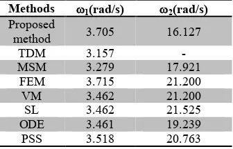
The first two natural frequencies are compared with those obtained by Top Displacement Method (TDM) [3], Mode Superposition Method (MSM) [3], Finite Element Method (FEM) (COSMOS/M1988) [16], Variational Method (VM) [17], Sturm-Liouville equation (SL) [4], ODE solver (ODE) [5] and Power-Series Solution (PSS) [7]. The capabilities of the proposed method and those of the previous published approximate methods are compared in Table 2.
TABLE 2. Comparison of natural frequencies of tube-in-tube tall building.
Methods 1(rad/s) 2(rad/s) Proposed
method 3.705 16.127
TDM 3.157
-MSM 3.279 17.921
FEM 3.715 21.200
VM 3.462 21.200
SL 3.462 21.525
ODE 3.461 19.239
PSS 3.518 20.763
The results of approximate proposed method are in good agreement with results available in the published literature.
5. DISCUSSIONS
It can be seen that the results calculated by the proposed method agree well with those obtained from a detailed finite element analysis and previous published methods. The difference of the natural frequency and corresponding mode shape of tube-in-tube tall building in the frequencies
computed by the proposed method and reference methods are within acceptable ranges. The main sources of error between the proposed approximate method and other methods are as follows [19-20]: (a) All closely spaced perimeter columns tied at
each floor level by deep spandrel beams considered to form a tubular structure.
(b) Modeling the frame panels as equivalent orthotropic membranes, so it can be analyzed as a continuous structure.
(c) The approximation to derive EI and GA
parameters.
(d) The effect of shear lag in the external and internal tubes has been neglected in assessing the global behavior of the tube-in-tube structures in approximate method.
The numerical example demonstrates the accuracy and simplicity of the proposed method as compared to previous published methods.
6. CONCLUSION
7. REFERENCES
1. Halis Gunel, M. and Emer Ilgin, H., "A proposal for the classification of structural systems of tall buildings",
Journal of Building and Environment, Vol. 42,
(2007), 2667-2675.
2. Taranath, B. S., "Structural Analysis and Design of Tall Buildings", McGraw-Hill, New York, (1988).
3. Youlin, Z., "Simplified analysis of tube-in-tube structures", Journal of Building Structures, China,
Vol. 5, (1984), 9–21.
4. Wang, Q., "Sturm–Liouville equation for free vibration of a tube-in-tube tall building", Journal of Sound and Vibration, Vol. 191, No. 3, (1996a), 349–355.
5. Wang, Q., "Modified ODE-solver for vibration of tube-in-tube structures", Computer Methods in Applied Mechanics and Engineering, Vol. 129, (1996b), 151–
156.
6. Lee, K. K, Loo, Y. C. and Guan, H., "Simple analysis of framed-tube structures with multiple internal tubes",
Journal of Structural Engineering, Vol. 127, No. 4,
(2001), 450-460.
7. Lee, W. H., "Free vibration analysis for tube-in-tube tall buildings", Journal of Sound and Vibration, Vol.
303, (2007), 287–304.
8. Chang, P. C., "Analytical modeling of tube-in-tube structure", Journal of Structural Engineering, ASCE,
Vol. 111, No. 6, (1985), 1326-1337.
9. Xin, K. G., Bao, S.H. and Li, W. Y., "A semi-discrete method for analysis of tube-in-tube structures", Journal of Computers and Structures, Vol. 53, No. 2, (1994),
319-325.
10. Kwan, A. K. H., "Simple method for approximate
analysis of framed tube structures", Journal of Structural Engineering, ASCE, Vol. 120, No. 4,
(1994), 1221-1239.
11. Meirovitch, L., "Computational methods in structural
dynamics", The Netherland Rockville, Maryland, U. S. A., (1980).
12. Shames, I. H. and Dym, C. L., "Energy and Finite Element Methods in Structural Mechanics Hemisphere", Washington, DC., (1985).
13. Behzad, M., Meghdari, A. and Ebrahimi, A., "A new approach for vibration analysis of a cracked beam",
International Journal of Engineering, Vol. 18, No. 4,
(2005), 319-330.
14. Sadeghian, M. and Ekhteraei Toussi, A., "Frequency analysis for a Timoshenko beam located on an elastic foundation", International Journal of Engineering, Vol. 24, No. 1, (2011), 87-105.
15. Mathematica 7.0.0, Wolfram Research Inc.
16. Lashkari, M., "COSMOS/M User's Guide, Structural Research and Analysis Corporation", California, USA, (1988).
17. Wang, Q., "The variational equation for solving natural vibration of tube in tube structure", China Journal, Building Structures, Vol. 10, No. 6, (1989), 64-70.
18. Rahgozar, R. and Sharifi, Y., "An approximate analysis of combined system of framed tube, shear core and belt truss in high-rise buildings", The Structural Design of Tall and Special Buildings, Vol. 18, No. 6, (2009),
607–624.

![Entends tu mes attitudes ? Perception de la prosodie des affects sociaux en chinois Mandarin (Do you hear my attitudes? Perception of Mandarin Chinese social affects’ prosody) [in French]](data:image/gif;base64,R0lGODlhAQABAIAAAP///wAAACH5BAEAAAAALAAAAAABAAEAAAICRAEAOw==)