THERMAL BEHAVIOR OF A NEW TYPE OF
MULTI-LAYERED POROUS AIR HEATER
S. A. Gandjalikhan Nassab
Department of Mechanical Engineering, School of Engineering Shahid Bahonar University of Kerman, Kerman, Iran
ganjali2000@yahoo.com
(Received: August 27, 2005 – Accepted in Revised From: November 2, 2006)
Abstract Based on an effective energy conversion method between gas enthalpy and thermal
radiation, a multi-layered type of porous air heater has been proposed. In the five layered structure which is analyzed in this work, there are five porous layers which are separated by four quartz glass windows. The main layer operates as a porous radiant burner that products a large amount of thermal radiative energy and in the other layers, the energy conversion process between gas enthalpy and thermal radiation takes place. In order to obtain the thermal characteristics of the heater, the coupled energy equations for the gas flows and porous layers are solved numerically by iterative method. The two–flux radiation model is used for computing the radiative fluxes from a solid matrix. Computational results show a very high efficiency for this type of porous air heater although it has a very simple structure.
Key Words Multi Layer-Energy Conversion-Air Heater-Porous Media
ﻩﺪﻴﮑﭼ
ﺍﻮﻫﮏﻳ،ﯽﻌﺸﻌﺸﺗﯼﮊﺮﻧﺍﻭﺯﺎﮔﯽﭙﻟﺎﺘﻧﺍﻦﻴﺑﯼﮊﺮﻧﺍﻞﻳﺪﺒﺗﻪﻳﺎﭘﺮﺑ
ﺯﺍﻩﺩﺎﻔﺘـﺳﺍﺎـﺑﯼﺍﻪـﻳﻻﺪـﻨﭼﻦﮑﻣﺮـﮔ
ﺖﺳﺍﻩﺪﺷﺩﺎﻬﻨﺸﻴﭘﻞﺨﻠﺨﺘﻣﻂﻴﺤﻣ
.
ﻪـﺘﻓﺮﮔﺭﺍﺮـﻗﻞﻴﻠﺤﺗﻭﻪﻳﺰﺠﺗﺩﺭﻮﻣﺮﺿﺎﺣﺭﺎﮐﺭﺩﻪﮐﯼﺍﻪﻳﻻﺞﻨﭘﻝﺪﻣﮏﻳﺭﺩ
ﺖﺳﺍ
.
ﺯﺍﯼﺍﻪﺸﻴﺷﻪﭽﻳﺭﺩﺭﺎﻬﭼﻂﺳﻮﺗﻪﮐﻩﺩﻮﺑﺩﻮﺟﻮﻣﻞﺨﻠﺨﺘﻣﻪﻳﻻﺞﻨﭘ ﺪـﻧﺍﻩﺪﺷﺍﺪﺟﺮﮕﻳﺪﮑﻳﺯﺍﺰﺗﺭﺍﻮﮐﺲﻨﺟ
.
ﯽـﻣﺭﺩﺎﺻﺩﻮﺧﺯﺍﺍﺭﯽﻬﺟﻮﺗﻞﺑﺎﻗﯽﺸﺑﺎﺗﺭﺎﺷﻪﮐﻩﺩﻮﻤﻧﻞﻤﻋﯽﺸﺑﺎﺗﻞﺨﻠﺨﺘﻣﻞﻌﺸﻣﮏﻳﻪﺑﺎﺸﻣﯽﻠﺻﺍﻪﻳﻻ ﺪـﻳﺎﻤﻧ
.
ﯽﻣﺕﺭﻮﺻﺲﮑﻌﻟﺎﺑﻭﺯﺎﮔﯽﭙﻟﺎﺘﻧﺍﻪﺑﯽﺸﺑﺎﺗﯼﮊﺮﻧﺍﻞﻳﺪﺒﺗﺪﻨﻳﺁﺮﻓﺎﻫﻪﻳﻻﯽﻘﺑﺎﻣﺭﺩ ﺩﺮﻳﺬﭘ
.
ﺑ
ﻪ
ﻢﺘﺴـﻴﺳﺰﻴﻟﺎـﻧﺁﺭﻮﻈﻨﻣ
ﻧﺍﺕﻻﺩﺎﻌﻣ،ﺮﻈﻧﺩﺭﻮﻣ
ﻞـﺣﯼﺭﺍﺮـﮑﺗﺕﺭﻮﺼـﺑﻭﯼﺩﺪـﻋﯼﺎﻬﺷﻭﺭﺯﺍﻩﺩﺎﻔﺘﺳﺍﺎﺑﻞﺨﻠﺨﺘﻣﻂﻴﺤﻣﻭﺯﺎﮔﯼﺍﺮﺑﯼﮊﺮ
ﯽﺗﺭﺍﺮﺣﺭﺎﺷﻭﺩﻝﺪﻣﺯﺍﺎﺘﺳﺍﺭﻦﻳﺍﺭﺩﻭﻩﺪﺷ
ﯼﺍﺮﺑ
ﺖﺳﺍﻩﺪﺷﻪﺘﻓﺮﮔﮏﻤﮐﯽﻌﺸﻌﺸﺗﺭﺎﺷﻪﺒﺳﺎﺤﻣ
.
ﻪـﮑﻨﻳﺍﺩﻮﺟﻭﺎﺑ
ﯼﺍﻩﺩﺎﺳﺭﺎﻴﺴﺑﯽﻠﺧﺍﺩﻥﺎﻤﺘﺧﺎﺳﯼﺍﺭﺍﺩﻢﺘﺴﻴﺳ ،ﺖﺳﺍ
ﻧﺎﻣﺪـﻧﺍﺭﻩﺪـﻨﻫﺩﻥﺎﺸﻧﻩﺪﻣﺁﺖﺳﺪﺑﺞﻳﺎﺘﻧ ﯽ
ﺎـﺑﺭﺎﻴﺴـﺑ
ﯼﺍﺮـﺑﻻ
ﻪﻃﻮﺑﺮﻣﻝﺪﺒﻣ ﯽﻣ
ﺪﺷﺎﺑ
.
1. INTRODUCTION
Many methods have been proposed for heat augmentation in high temperature facilities by utilizing thermal radiation. The effective energy conversion method from flowing gas enthalpy to thermal radiation from porous metal plates can be given as one of the most promising methods [1-3]. Applying this conversion method, Tomimura et al. [4] has proposed a new type of multi-layered gas-to-gas heat exchanger equipped with circular porous metal plates. From their theoretical studies conducted on a high temperature combustion gas, it was shown that this type of heat exchanger has much higher overall heat transfer coefficient than
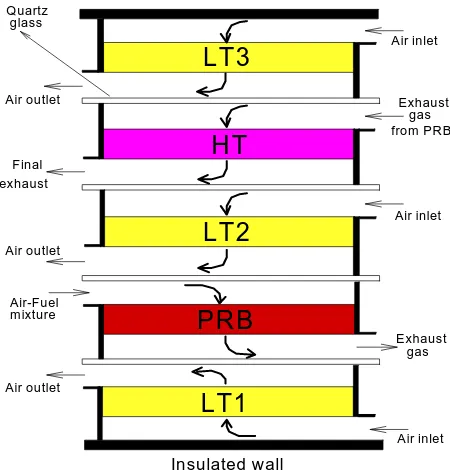
PRB
LT1
LT2
LT3
HT
Air outlet
Air inlet Exhaust
gas
Air-Fuel m ixture
Air inlet
Air outlet
Insulated wall
Exhaust gas from PRB
Final exhaust
Air inlet Air outlet
Quartz glass
Figure 1. Geometrical configuration of porous air heater.
thermal radiation into gas enthalpy.
Porous radiant burners (PRBs) are one of the other applications of porous materials in thermal systems. In PRBs, the heat of combustion released in the gas phase heats up the solid matrix, which in turn emits energy in the form of thermal radiation to a heat load. Numerical results which were obtained by many investigators show that this type of burner has many advantages over conventional ones [6].
In the present work, PRB is used to develop an efficient porous air heater (PAH) as a new type of heat exchanger which has a five–layered structure and operates as a self-dependent system. The schematic outline of the system is shown in Figure 1. The five sections of the heater are as follows: porous radiant burner (PRB), first low temperature section (LT1), second low temperature section (LT2), high temperature section (HT) and third low temperature section (LT3). The porous layers in each section are separated from each other by quartz glass windows. In PRB, the heat of combustion is converted into thermal radiation emitted towards LT1 and LT2. The porous layers in these two low temperature sections are heated by absorbing the emitted radiation from PRB and consequently the low temperature airflows through the porous layers are effectively heated by the energy conversion process from thermal radiation into gas enthalpy. Since, the temperature of exhaust flow from PRB is still high, and in order to improve the performance of the system, a high temperature section (HT) is designed so that the enthalpy of exhaust gas from PRB converts to thermal radiation emitted towards LT2 and LT3 where the reverse conversion from thermal radiation into gas enthalpy takes place.
As a result of high porosity of porous medium, thermal conductivity in this media is low. Thereby, in the numerical simulation of PAH, it is assumed that convection and radiation take place in a porous matrix. However, in the gas flow because of non-radiating gas assumption, heat transfer occurs by conduction and convection. The combustion process in PRB is modeled as a especially dependent heat generation zone and it is assumed that the five porous layers in PAH are perfectly similar to each other and have the same physical properties.
In order to investigate the thermal characteristics
of PAH, simultaneous solution of the governing equations at each section are obtained by a numerical method. These equations for each section are the energy equations for the gas and solid phases with two radiative transfer equations which were written based on two-flux radiation model.
2. THEORETICAL ANALYSIS
In all of the sections in PAH, there exists a gas flow through a porous layer along with a convective heat transfer process between solid and gas phases. Thereby, the governing equations for thermal analysis of PAH are the same for all five sections, but in PRB where the combustion process takes place, the heat of combustion as a source term is added into the gas energy equation. To save space, only the governing equations and the method of solution for analyzing PRB are presented here.
o o o o o o o o o o o o o o o o o o o o o o o o o o o o o o o o o o o o o o o o o o o o R0 Air-Fuel mixture
Tg 0, ug x
1
xf c
x2
hw , T8
Porous medium Combustion zone
Radiative
heat flux
δf
Radiative
heat flux
Figure 2. Schematic diagram of the porous radiant burner.
generation zone representing the flame with a thickness of
δ
f , is situated in the porous region. The solid matrix is assumed to be gray which absorbs, emits and scatters thermal radiation. Radiant energy emitted is assumed to be primarily due to continuum emission by the solid matrix. Comparatively, gaseous radiation is not as important as solid radiation and is neglected. Since, the solid and gas are not in local thermal equilibrium, separate energy equations are needed to describe energy transfer in these two phases. These energy equations along with the radiative transfer equations can be written as follows [8]:0 ) 2 0 R π ( ) x ( δ Q ) 2 0 R π ( ) 2 x d g T 2 d ( g K ) P T g T ( ) 2 0 R π ( s A s N s h ) T g T ( ) 0 R π 2 ( w h ) 2 0 R π ( dx g T d g c g ρ g u = − − − + ∞ − + & (1) 0 x d n q d ) g T p (T s A s N s
h − + = (2)
− + + + − + − = + q s 2bσ 4 P σT a 2σ q s 2bσ q a 2σ dx
dq (3)
+ − − − + + − − =
− 2σ q 2bσq 2σσT 2bσq
dx dq s 4 P a s
a (4)
− − + =q q n
q (5)
In Equation 1, which is the energy equation for the gas flow, the first term is the variation of gas convective energy while the second and third terms are the convective heat transfer from the gas flow to the surrounding and solid phase, respectively. The next term is the conductive heat transfer through the gas phase and finally the last term is due to the heat generation inside the combustion zone. In the porous energy equation, the first term is the convective heat transfer between the solid and gas phases and the last term is the variation of radiative heat flux along the porous segment. The radiative heat fluxes along the burner are computed by Equations 3 and 4 which are written based on the two flux radiation model. The readers are referred to Ref. [9] for the computational details of this model.
For parametric studies, the governing equations are non-dimensionalized by introducing the following dimensionless parameters:
g g g w w c u h P ρ = 4 g , , 0 T q Q σ = +− − + 3 g g g g 0 T 2 c u σ ρ = λ . Q T c u
P g g g g0 1 δ ρ = g 0 g g g K R c u
Pe= ρ τ=σex
g g g 0 s s s c u R A N h Q ρ = 0 R x X= e s σ σ = ω 0 0 3 g e s s s g R Q T 2 A N h R T T 0 0 e
0 = λ× τ × δ
σ σ = = θ δ σ = τ
0 0 .2 5 0 .5 0 .7 5 1 0
2 4 6 8 1 0
τ
Θg
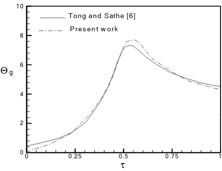
T o n g an d S ath e [6 ] P resen t w o rk
Figure 3. Gas temperaturedistribution alongthe burner: 272 Pe , 227 , 1468 Q , 1 , 2 . 0 R
/ 0 = τ0= = λ= =
δ 0
Pw = , ξfl =0.5, ω=0.5, b = 0, θ∞ =1, P1 = 0.0136. )
Q Q )( 1 ( P ) 1 ( 2 ) P g (
R θ −θ = −ωθ 4− −ω ++ − (7)
− +
+ +
ω + θ ω − + ω − ω − − =
τ 2(1 )Q 2b Q 2(1 ) 2b Q
d
dQ 4
P (8)
+ −
− −
ω θ ω − ω
ω =
τ − − − + +
− 2(1 )Q 2b Q 2(1 ) 2b Q
d
dQ 4
P (9)
Non-dimensional forms of the governing equations are solved numerically to obtain the temperature and radiative heat flux distributions along the burner. Equations 6 to 9 are coupled and should be solved simultaneously. For this purpose, the finite difference form of the gas energy equation is obtained using central differencing for derivative terms where the error of discretization is the order of (ΔX)2 and the radiative transfer equations are
solved by forth order Runge–kutta method. The sequence of calculations can be stated as follows: 1. A first approximation for temperature and
radiative flux distributions is assumed.
2. Using Thomas-Algorithm, the discretized form of the gas energy equation is solved for obtaining the value of
θ
g at each nodal point. 3. Using the values ofθ
g which were obtainedin step 2, the radiative transfer equations are solved by Runge–Kutta method to calculate the radiative flux distributions Q+ and −
Q . 4. The algebraic Equation 7 is solved to
determine the temperature of solid matrix. Steps 2 to 4 are repeated until convergence is obtained. This condition was assumed to have been achieved when the fractional changes in the temperature and radiative flux between the two consecutive iteration levels did not exceed 10−4 at each grid point.
3. RESULTS AND DISCUSSION
In order to validate the computational results, a PRB is analyzed as a self–dependent system in a test case and the numerical results are compared with theoretical predictions in Ref. [6]. The gas temperature distribution along the burner is shown in Figure 3.
It is seen that the incoming fuel–air mixture is heated by a radiative process as it passes through
the porous media before the combustion zone. The maximum gas temperature occurs inside the heat generation zone to a point that the radiation serves as a mechanism for heat removal from this region. There is a decrease in gas temperature after the combustion zone by converting gas enthalpy to thermal radiation. However, Figure 3 shows good consistency between the present results and those obtained in Ref. [6].
Based on the theoretical studies of PRBs and the principle of energy conversion between gas enthalpy and thermal radiation, which was discussed in the previous sections, the thermal behavior of the new type of five layered PAH is analyzed here. The situation considered is shown schematically in Figure 1. All of the five layers in PAH have a radius equal to R0 and the spacing between two adjacent layers is equated to R0/4,
which gave a configuration factor of 0.8.
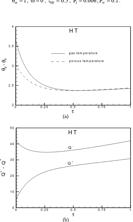
In order to show the thermal behavior of PRB which has the main role in the designed PAH, the gas and porous temperature profiles θg and θp, and also the variation of radiative fluxes +
Q and −
Q along the burner are shown in Figure 4. The
0 0 .2 5 0 .5 0 .7 5 1 0
2 4 6 8 1 0 1 2
P R B
P o r o u s t e m p e r a t u r e G a s t e m p e r a t u r e
τ
θ
θg
,
p
(a)
0 0 .2 5 0 .5 0 .7 5 1
0 1 0 0 2 0 0 3 0 0 4 0 0
P R B
Q
Q
-τ
Q+
Q
+
-,
(b)
Figure 4. Temperature (a) and radiative flux (b) distributions
along the PRB:
153 Pe , 71 . 9 , 200 Q , 1 , 1 . 0 R
/ 0= τ0= = λ= =
δ
1 . 0 P , 006 . 0
P1= w = , ξfl=0.5, ω=0, θ∞ =1.
middle of porous segment). In the computations, the ratio of δf /δ is equal to 0.1.
As it is seen in Figure 4–a, the gas and porous temperatures increase along the flow direction at the entrance of the burner. The effect of gas preheating is clear in this figure such that for locations upstream of the heat release zone, the solid temperature is greater than the gas temperature. Figure 4–b shows that the maximum
values of +
Q and Q− occur outside the combustion
zone. The values of the downstream radiative flux
+
Q at τ =τ0 and upstream radiative flux Q− at 0
=
τ
are the radiative outputs from PRB which are the energy sources in PAH. These radiative energies must be absorbed in the first and second low temperature sections in order to increase the air flow temperature via a convective heat transfer process.Figure 5 shows the air temperature distributions in the three low temperature sections. It is seen that the airflows are effectively heated as they pass through the porous layers in these sections. The temperature increase in LT1 and LT2 are much higher than LT3, because the two low temperature sections LT1 and LT2 are closed to PRB which has the main energy source.
The gas and porous temperature distributions in the HT section are shown in Figure 6–a. It is mentioned that the exhaust gas from PRB is the entering flow into HT section. Figure 6–a shows that the gas temperature decreases as it passes across the porous layer because of heat exchange with the solid phase. By this convective heat transfer, the solid temperature tends to rise too close to the fluid temperature and there is a large amount of radiative flux emitted from porous media into the adjacent layers. The radiative heat flux distribution along the porous layer in the HT section is shown in Figure 6–b. The values of
) (τ0
+
Q and Q−(0) are the recaptured energy which are emitted towards the LT2 and LT3 sections. Figure 7 shows the effect of τ0,
ω
and P1 onthe PAH efficiency which is defined generally by the following equation:
f 2 0
ao 3
LT , 2 LT , 1 LT
P a
R . Q
) T T ( c m η
a
δ π
− =
∞
∑
&(10)
Here, m&a and cpa are the mass flow rate and the specific heat at constant pressure of the air flow,
ao
0 0 . 2 5 0 . 5 0 . 7 5 1 1
1 . 5 2 2 . 5 3 3 . 5
L T 3 L T 1
L T 2
AI
R
T
EMPER
A
TU
R
E
τ
Figure 5.Air temperature distributions in the porous layers of
LT1, LT2 and LT3:
153 Pe , 71 . 9 , 200 Q , 1 , 1 . 0 R
/ 0= τ0= = λ= =
δ 1 =
θ∞ , ω=0, ξfl=0.5, P1=0.006,Pw =0.1.
0 0 .2 5 0 .5 0 .7 5 1
2 2 .5 3 3 .5 4
H T
p o r o u s t e m p e r a t u r e g a s t e m p e r a t u r e
θ
θg
,
p
τ
(a)
0 0 .2 5 0 .5 0 .7 5 1
0 1 0 2 0 3 0 4 0 5 0
Q
-Q Q+
,
Q
+
-H T
τ
(b)
Figure 6. Temperature (a) and radiative heat flux (b)
distributions in HT section:
153 Pe , 71 . 9 , 200 Q , 1 , 1 . 0 R
/ 0= τ0= = λ= =
δ
1 . 0 P , 006 . 0
P1= w =
,
ξfl=0.5,
ω=0,
θ∞ =1.
equation can be written for the computation of PAH efficiency.
] LT3 )
θ
ao
θ
( LT2 )
θ
ao
θ
( LT1 )
θ
ao
θ
( [ f
δ δ
1 P
η= − ∞ + − ∞ + − ∞
(11) It is seen from Figure 7 that the PAH efficiency increases by increasing the optical thickness of porous layers to a point that the optical thickness about 3 seems enough to obtain maximum efficiency. The effect of non-dimensional parameter P1 on the efficiency of PAH is also
shown in Figure 7. One of the main factors in the computation of this parameter is the heat generation rate in the combustion process, the large values of Q. causes a small values for P1. Figure 7
shows that increasing in the value of the heat generation rate in the combustion zone of PRB, causes a decrease in PAH efficiency. This is due to the fact that a PAH with a high heat generation rate in the combustion zone has a hot exhaust which is the wasted energy.
The effect of radiative scattering on the PAH efficiency is also shown in Figure 7. It is seen that radiative scattering causes a decrease in efficiency of PAH especially for small optical thicknesses. However, it is seen from Figure 7 that this type of air heater has a very high efficiency which is higher than the conventional ones with a maximum efficiency about 25% [7].
In the present study, a three-layered PAH is also analyzed in order to make a comparison between its efficiency with a five-layered one. It must be noted that in a three-layered PAH, there only exists LT1, LT2 and PRB sections.
It is seen from Figure 8 that there is a considerable difference between the efficiencies of these two types of PAH especially in the condition of large optical thicknesses for porous layers.
4. CONCLUSIONS
0 1 2 3 0
0 .1 0 .2 0 .3 0 .4 0 .5
P1= 0 .0 0 6
τ0
E
F
FI
CI
E
N
CY
P1= 0 .0 0 3
P1= 0 .0 1
ω = 0 .3 , ω = 0
b = 0 .5
Figure 7. Effects of 1
P ,
ω
andτ
0 on the PAH efficiency:153 Pe , 71 . 9 , 200 Q , 1 . 0 R
/ 0= = λ= =
δ
1 =
θ∞ , ξfl=0.5, Pw =0.1.
0 1 2 3
0 0 .1 0 .2 0 .3 0 .4 0 .5 0 .6
P1= 0 .0 0 6
P1= 0 .0 1
F iv e la y e r d s t r u c t u r e T h r e e la y e r d s t r u c t u r e
τ0
E
FFICI
E
N
CY
Figure 8. Comparison between three and five-layered PAH
efficiencies:
153 Pe , 71 . 9 , 200 Q , 1 . 0 R
/ 0= = λ= =
δ
1
=
θ∞
,
ξfl=0.5,
Pw =0.1.
converted into thermal radiation in a porous radiant burner and the energy conversion process form thermal radiation into gas enthalpy is occurred in low temperature sections. In order to improve the thermal performance of the system, a high temperature section is also considered to recover the enthalpy of exhaust gas from PRB which otherwise will be wasted. Heat transfer characteristics of the newly proposed porous air heater is investigated by solving the governing
equations for the gas and solid phases and the two-flux model is used to describe the radiative two-flux from the solid matrix. Numerical results show a very high efficiency for this type of porous air heater.
5. NOMENCLATURE
A Surface area, (m2)
B Back–scattered fraction factor B Incoming radiation (W/m2)
p
c Specific heat (J/kg°C)
h Heat transfer coefficient (W/m2°C)
K Thermal conductivity (W/m°C) .
m Mass flow rate (Kg/s)
− +,
q Radiative heat fluxes in downstream and upstream directions (W/m2)
0
R Radius of duct (m )
T Temperature (°C)
o a
T Temperature of air at the outlet of LT
section (°C) `
0 g
T Gas temperature at duct's inlet (°C)
u Velocity(m/s)
x Coordinate along the flow direction ( m ) fc
x Location of flame center (m )
δ Thickness of porous layer ( m )
θ Non–dimensional temperature, T/Tg0 Θ Non–dimensional temperature, (T−T∞)/T∞
f
δ Thickness of flame zone (m)
l
f
ξ Dimensionless flame zone location,
) x x /( ) x x
( fc− 1 2− 1
Greek Letters
ρ Density (kg/m3)
σ Stefan–boltzmann constant (W/m2K4)
s
σ Scattering coefficient (m−1)
a
σ Absorbing coefficient (m−1)
e
σ Extinction coefficient (m−1)
τ
Optical depth, e(x x ) 1− σ
0
Subscripts
g, p gas and porous, respectively w wall
1, 2 inlet and exit of porous layer
n algebraic summation
a air
o outlet ∞ ambient
6. REFERENCES
1. Echigo, R., “Effective energy conversion method between gas enthalpy and thermal radiation and application to industrial furnaces”, Proc. 7th Int. Heat Transfer Conf., München, Vol. 6, (1982), 361-366. 2. Echigo, R., “Heat transfer augmentation in high
temperature heat exchangers”, High Temperature Equipment, Hemisphere, Washington, DC, (1986), 41-72.
3. Wang, K. Y. and Tien, C. L., “Thermal insulation in flow systems combined radiation and convection
through a porous segment”, J. Heat Transfer, Vol.
106, (1984), 453-459.
4. Tomimura, T., Onizuka, A., Hamano, K. and Echigo, R., “Application of effective energy conversion method by porous metal to multilayerd type of gas–to– gas heat exchanger’’, 2nd Japan-Korea Joint Symposium on Energy and Environment Program,
(15 October, 2002), 10-15.
5. Gandjalikhan Nassab, S. A., “Effective gas–to–gas heat exchanger by means of energy conversion between gas enthalpy and thermal radiation”, Proc.
Instn. Mech. Engrs.:J. Power and Energy, Vol. 218, Part A, (2004), 451-457.
6. Tong, T. W. and Sathe, S. B., "Heat transfer characteristics of porous radiant burners", Trans. ASME: Journal of Heat Transfer, Vol. 113, (1991), 423-428.
7. Tomimura, T., Hamano, K., Honda, Y. and Echigo, R., “Experimental study on multi-layered type of gas–to– gas heat exchanger using porous media“, Int. J. Heat and Mass Transfer, Vol. 47, (2004), 4615-4623.
8. Gandjalikhan Nassab, S. A., “Transient heat transfer characteristics of an energy recovery system using a porous medium”, Proc. Instn. Mech. Engrs.: J. Power
and Energy, Vol. 216, Part A, (2002), 387-394.