GA-Based Optimal LQR Controller to Improve LVRT
Capability of DFIG Wind Turbines
A. Khajeh* and R. Ghazi*
Abstract: Nowadays, the Doubly-Fed Induction Generators (DFIGs) based Wind Turbines
(WTs) are the dominant types of WTs connected to grid. Traditionally the back-to-back converters are used to control the DFIGs. In this paper, an Indirect Matrix Converter (IMC) is proposed to control the generator. Compared with back-to-back converters, IMCs have numerous advantages such as: higher level of robustness, reliability, reduced size and weight due to the absence of the bulky electrolytic capacitor. According to the recent grid codes it is required that the wind turbines remain connected to the grid during the grid faults and the following voltage dips. This feature is called Low Voltage Ride-Through (LVRT) capability. In this paper, the Linear Quadratic Regulator (LQR) controller is used for optimal control of the DFIG. The weighting matrices of the LQR are obtained by using the Genetic Algorithm (GA) technique. With the LQR controller the intention is to improve the LVRT capability of the DFIG wind turbines to satisfy the new LVRT requirements. Compared to the PI controller, the superiority of the LQR controller in improving the transient stability and LVRT performance of the DFIG wind turbines is shown. Simulation results confirm the efficiency of the proposed controller.
Keywords: Indirect Matrix Converter, LQR Controller, LVRT, Wind Turbine.
1 Introduction1
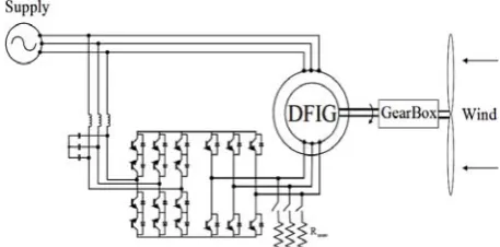
Wind energy has been found as the fastest growing renewable power generation resources over the world. Due to their superior characteristics, most of the grid-connected WTs operate at a variable speed. Among the different variable speed types, the DFIG is the dominant one. The stator winding of the DFIG is directly connected to the grid, while the rotor winding is connected to the grid through an AC-AC power electronic converter. Traditionally the back-to-back converters are used to excite the rotors of the DFIGs. The presence of the dc-link capacitor in this arrangement is a serious drawback as increases the costs and reduces the overall lifetime of the system and also makes the system bulky [1]. In this paper, the back-to-back converter is replaced by an indirect matrix converter (IMC) which is a more robust and reliable device and also offers a more compact design Fig. 1.
In the past, based on most grid codes, wind turbines were allowed to be disconnected from the grid during the grid disturbances and abnormal voltage dips. With the increased capacity of wind power over the years, the
Iranian Journal of Electrical & Electronic Engineering, 2013. Paper first received 16 Apr. 2013 and in revised form 16 June 2013. * The Authors are with the Department of Electrical Engineering, Ferdowsi University of Mashhad, Mashhad, Iran.
E-mails: [email protected], [email protected].
sudden loss of wind turbines during the grid faults could cause control problems of frequency and voltage in the system. To handle this issue the grid codes are revised by system operators in several countries [2]. According to the new grid codes the wind turbines must stay connected to the network on the occurrence of grid faults. This feature is known as the low voltage ride-through (LVRT) capability of a power plant. The LVRT of the Denmark grid code will be discussed in section 2.
Because of the direct connection of the DFIG stator winding to the grid and the low rating of the power electronic converter in its rotor side, the DFIG based wind turbine is very sensitive to grid disturbances, especially to voltage dips during grid faults. At present, the back-to-back converter is the most frequently used power electronic converter in the wind turbines industry. Therefore, the most of research works have been done to enhance the LVRT ability of DFIGs utilizing these types of converters. The grid fault causes over current in the rotor windings and over voltage in the dc-link capacitor, hence the proper protection should be provided to safekeeping the converter. Various solutions have been proposed to solve the problem. Some of them are briefly reviewed here.
The most popular and reliable method is based on the use of a protective circuit known as crowbar. The
Fig. 1 Wind Turbine based on the DFIG excited by indirect matrix converter.
crowbar consists of resistors connected to the rotor windings by means of electronic switches. When a fault occurs, the rotor windings get connected to the crowbar while the converter is tripped. Several papers have discussed the implementation and control of crowbars [3] [7]. The crowbar can effectively protect the rotor converter under serious grid faults. However, the main drawback is that, when the crowbar is activated, the rotor converter can no longer control the active and reactive power.
Another approach is to modify the rotor-side converter control system to limit the fault currents without using any extra hardware [8]- [10]. As described in [11], the rotor currents set points are changed to the measured values of the stator currents in the d-q reference frame to reduce the initial large fault currents. To account for uncertainties and the terminal voltage variation of the DFIG, a robust controller using H-infinity and µ-analysis is developed in [12]. The ride-through control of the DFIG during an asymmetrical grid fault is reported in [13]. However, following a sever grid fault all of them may fail as the required voltage in the rotor-side converter becomes too large and exceeds its voltage capability. These methods are beneficial as they do not require any additional hardware but applicable only for moderate faults.
Another solution for LVRT is to use an additional Energy Storage System (ESS) connected to the dc-link [14]- [17]. The ESS can balance the extra power that passes through the rotor circuit during a grid transient fault. However, the rotor side converter should also have a higher current rating with additional cost and system complexity.
Utilizing the matrix converters in DFIG wind turbines is still in the research stage. Most of the works have dealt with their normal operation [18]- [22]. In [21], the dynamic performance of the DFIG using the IMC under the voltage dip condition has been discussed . The simulation results of this reference show that at 80% terminal voltage drop, the stator current reaches to 2.5pu which may damage the IGBT switches of the IMC. The results also indicate that during the fault nearly 0.7 pu reactive power is absorbed from the grid which makes the voltage deeper. This is when it is imperative that the reactive to be injected for improving
the recovery of voltage during and after grid faults, in accordance with the new LVRT standards. Therefore, it can be concluded that the existing controller which is designed for normal operating conditions will not be much effective during the grid faults especially the severe ones.
The DFIG usually operates in vector control mode based on PI controllers in synchronous reference frame oriented to the stator flux or the stator voltage. The DFIG performance with PI controllers is satisfactory in normal grid conditions, but it may not be guaranteed especially under large disturbances. For the PI controllers design, a simple first order SISO model of the DFIG is commonly used. However, such controller can work well in satisfying the older grid code requirements not the recent one. Therefore, new methods for the design of controllers for the WTs having DFIGs have been investigated by some authors to achieve a better control performance in terms of transient stability of power systems [23]- [26].
To improve the LVRT capability, in this paper, the linear quadratic regulator (LQR) controller is proposed and its performance is examined in comparison with a well-tuned PI controller in the presence of grid faults. The LQR is based on the modern control theory and can be applied to complex MIMO, linear or nonlinear systems [23]. The Q and R weighting matrices of the LQR are optimized using the GA technique. The well-known and popular concept of LQR offers a highly advantageous method for optimally tuning controller gains in a feedback system. The LQR problem is to design a full state feedback control law such that optimally regulates the states and its output to zero. The LQR design can improve the controller robustness against the system parameters uncertainties, resulting in 60o of phase and infinite gain margins.
This paper is organized as follows. In section 2, LVRT requirement of a Denmark transmission system operator is discussed. Modeling and control of the DFIG based wind turbine is presented in section 3. The vector control of the DFIG is briefly discussed in section 4. In section 5, the proposed LQR controller is presented and discussed. The simulation results are provided in section 6. Finally, section 7 concludes the paper.
2 LVRT Requirement
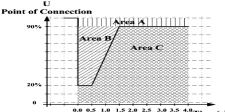
Due to the high penetration of wind power, the Denmark transmission system operator Energinet.dk has introduced a voltage profile, the limiting curves and regions defining the LVRT requirement as shown in Fig. 2. It is inferred from this figure that the wind turbines must stay connected even when the voltage at the Point Of Connection (POC) drops to 20% over a period of minimum 0.5 s. It is allowed to use the voltage measurement for the individual wind turbine generator system to perform regulation during voltage drops. The area A shows the normal terminal voltage tolerance of the wind turbine. The wind power plant must stay
Fig. 2 Energinet.dk LVRT requirement
connected within the area B, and must provide maximum voltage support by supplying a reactive current so as to ensure that the wind turbine helps to stabilize the voltage. Below the limit line, the area C, disconnecting the wind turbine is allowed.
According to the Energinet.dk grid code, wind turbines have to provide a mandatory voltage support during voltage dips in area B. Wind turbines have to supply 1pu reactive current when the voltage falls below 50% with a tolerance of 20% after 100 ms. The supply of reactive power is the first priority in area B, while the supply of the active power is the second priority.
3 Modeling and Control of the DFIG Based Wind Turbine
In this section, the dynamic model of a DFIG based wind turbine is provided.
3.1 Turbine Model
The mechanical power extracted by a wind turbine from the wind is expressed by
3
1
. . ( , ).
2 p
P= AρC λ β vω (1) where A is the area covered by the rotor blades, ρ is the air density, Cp is the power coefficient, representing the
amount of power the turbine can extract, and vω is the wind speed. The power available in the wind cannot be extracted completely. Theoretically the maximum captured power is 59% of the power available in the wind. The power coefficient is a function of the tip-speed ratio λ and the pitch angle of the rotor blades β. The tip-speed ratio is defined by:
t R
vω
λ
= Ω (2)where R is the radius of the rotor blades and Ωt is the
angular speed of the blades. For each pitch angle of the rotor blades, there is an optimum tip-speed ratio λopt for
which Cp(λopt,β) takes a maximum value. Therefore, for
wind speeds below the rated value, the existing power is below the rated power, so power coefficient is optimized by adjusting the tip-speed ratio to achieve the maximum power coefficient. The pitch angle is then kept constant in this region. On contrary, at wind speeds
above rated value the extracted wind power has to be limited by means of blade pitching. This process is called the Maximum Power Point Tracking (MPPT) of wind turbines. In this paper the MPPT is accomplished through a look-up table. The MPPT table ensures that the plant operates at maximum power for partial loads and specifies that the rated speed is achieved at rated power. According to [27] coordination between the control of the mechanical and the electrical system exists.
3.2 DFIG Model
For DFIG modeling a fifth-order dynamic model is used in this paper. For the purpose of simulation and control it is common to express its quantities on d-q axes which form a reference frame that rotates synchronously with the stator flux vector [11], [28]. Eliminating the flux linkage terms and choosing the currents as states, the state space model of the DFIG is obtained as:
A B G
C d
x x u d
dt
y x
= + +
= (3)
The state, input, disturbance vectors and the state space matrices have been chosen as follows, respectively:
T T T
; u= ; d=
sd sq rd rq rd rq sd sq
x= ⎣⎡i i i i ⎦⎤ ⎣⎡v v ⎤⎦ ⎡⎣v v ⎤⎦
1
0
1 0
1 0
A ; B=
1 1 0 1 1 0 1 0 G= 0 0
k k k
s R m s r s
k
s r l
k k k k
R m s r s s l
s r
k
kr r rk R s m Lr
s r
L k
k k s m R r
r r r
s r
Ls
Ls kl
kl
ω ω ω
στ σ στ σ
ω ω ω
σ στ σ στ
ω ω
ω σ
στ σ στ σ
σ
ω ω
ω
σ στ σ στ
σ σ ⎡ − ⎤ ⎢ − ⎥ ⎢ ⎥ ⎡− ⎤ ⎢ ⎥ ⎢ ⎥ ⎢ − ⎥ ⎢ − ⎥ ⎢ − − ⎥ ⎢ ⎥ ⎢ ⎥ ⎢ ⎥ = ⎢ − ⎥ ⎢ ⎥ ⎢ − − ⎥ ⎢ ⎥ ⎢ ⎥ ⎢ ⎥ ⎢ ⎥ ⎢ ⎥ ⎢ − ⎥ ⎢⎣ ⎥⎦ ⎢ − ⎥ ⎢ ⎥ ⎣ ⎦ ⎡ ⎢ ⎢ ⎢ ⎢ ⎢ ⎢ ⎢ − ⎢ − ⎣ 2
; 1 , , , ,
2
, , ,
Lm Ls Lr Lm
k
s r s
L Ls r Rs Rr Ls
Lm Lm Lm
kr km kl R s r
Lr L Ls r L Ls r
σ τ τ
ω ω ω
σ ⎤ ⎥ ⎥ ⎥ ⎥ = − = = = ⎥ ⎥ ⎥ ⎥ ⎢ ⎥⎦ = = = = − (4) where Rs , Rr , Ls and Lr are the resistances and
inductances of the stator and rotor windings, Lm is the
magnetizing inductance, vsdq, vrdq, isdq and irdq are the
space vectors of the stator and rotor voltages and currents respectively, ωs is the synchronous speed of
generator, ωr is the electrical speed of rotor, and σ is the
leakage factor.
3.3 Indirect Matrix Converter
Due to the numerous advantages of matrix converters over back-to-back converters, in this paper the IMC is used to control the DFIG. Compared to the back-to- back converters the matrix converters are more robust, reliable and provide sinusoidal input and output waveforms, bidirectional power flow, controllable input power factor, and a more compact design. The Direct Matrix Converter (DMC) may encounter the commutation problems hence, requiring a complex control circuitry. While in IMC all switches at the line side will turn on and off at zero current, so the commutation problems are eliminated [29]. Therefore, the IMC can be a proper choice for wind energy applications.
An IMC consists of a rectification part on the input side and an inversion part on the output side, connected via fictitious dc-link as shown in Fig. 1. The rectifier has six bidirectional switches with the ability of conducting current and blocking voltage in both directions. The rectifier function is to achieve maximum positive voltages at the fictitious dc-link and sinusoidal input currents. Usually the grid side converter of DFIG exchanges zero reactive power at the grid point. In order to obtain maximum dc-link voltage, the input phase voltage which has the highest absolute value is connected to the positive or negative rail of the dc-link at 60 degree intervals depending on its polarity. To achieve sinusoidal current and unity power factor at the input side, regardless of the load type, the other two phase voltages modulated so that the reference current space vector be in phase with the voltage space vector. On the output stage, the Space Vector Modulation (SVM) is used to generate the required rotor voltage space vector by currents controllers. Detail description of the IMC modulation technique is provided in [21].
For the purpose of analysis, we assume that the switching frequency is far greater than the fundamental frequency of both the input voltage and output current. Thus during each switching cycle, it is assumed that both input voltage and output current are constant.
4 Vector Control of DFIG
The goal of the DFIG controller is the independent control of the stator active and reactive powers. The active power reference is determined by MPPT algorithm and that of the reactive power is set to obtain the desired power factor. Stator flux in d-q reference frame is the most widely used DFIG vector control in the wind turbine applications. Thus, the inverter of IMC is controlled in a stator flux d-q reference frame, with the d-axis oriented along the stator flux vector position. In the DFIG, the rotor voltages are control variables that control the rotor currents. The rotor voltages can be written as [9].
( ) ( )( )
( ) ( )( ) (5)
m
dr r dr r dr s s r r qr
s
m
qr r qr r qr s r r dr s
s L
d
v R i L i L i
dt L
L d
v R i L i L i
dt L
σ ψ ω ω σ
σ ω ω σ ψ
= + + − −
= + + − +
In steady state, the stator flux is proportional to the grid voltage. Neglecting the small voltage drop in the stator resistance, the voltage aligns with q-axis. Finally, when the d-axis is oriented to the stator flux, the active and reactive powers are given by [12].
3 2 3
( )
2 m s s qr
s s
s s m dr s
L
P V i
L V
Q L i
L ψ = −
= −
(6)
The above equations clearly show that under the stator flux orientation, the active and reactive powers are decoupled and can be controlled via the rotor currents. So, the active and reactive powers can be independently controlled by iqr and idr respectively.
Using the above equations, the reference currents can be calculated from the desired powers.
5 LQR Control of the DFIG
The LQR controller design is started from the state space representation of the system. The state space model of the DFIG is derived in the synchronous reference frame aligned with the stator flux in Eq. (3). Based on the vector control principle of the DFIG in the stator flux reference frame, the q-axis current of the rotor (iqr) controls the active power and the d-axis
current (idr) controls the reactive power of the DFIG.
Therefore, the d-q components of the rotor current are the desired outputs of the DFIG in wind power applications. The reference currents can be calculated from the desired powers using Eq. (6). One drawback of the LQR is that it addresses a regulation problem so cannot originally be applied to a tracking problem, which is desire in practice. However, an integrator can be added in series with the plant to overcome the tracking problem, and guarantees the zero steady state error [30]. The block diagram of the augmented system is shown in Fig. 3.
In the augmented system, the differences between system and the command references are fed to an integrator to form new states. The overall state space of the augmented system is as:
A B G
C
x x u d
d
z y r
dt
y x
+ +
⎡ ⎤ ⎡ ⎤
=
⎢ ⎥ ⎢ − ⎥
⎣ ⎦ ⎣ ⎦
=
(7)
Fig. 3 The DFIG state space model augmented by an
integrator.
Fig. 4 Chromosome structure.
Therefore, the new state space model of the system can be derived as
C d
x Ax Bu Br Gd
dt
y x
= + + +
=
(8)
where
[
]
[
]
0
, ,
0 0
0
, , 0
0
T A B
x x z A B
C G
B G C C
I
⎡ ⎤ ⎡ ⎤
= =⎢ ⎥ =⎢ ⎥
⎣ ⎦ ⎣ ⎦
⎡ ⎤ ⎡ ⎤
=⎢ ⎥ =⎢ ⎥ =
⎣ ⎦ ⎣ ⎦ .
In the model n
x∈R is the state vector, u∈Rm is the control input vector, d∈Rm is the system disturbance vector, p
y∈R is the output vector, and
, , , ,
n n n m n m n m p n
A∈R × B∈R× B∈R × G∈R× C∈R × are constant matrices of the state space equations. Applying the LQR to a state space model requires that the pair of (A,B) to be controllable, a condition that is true in this case. In the LQR problem, the optimality is measured by the following quadratic index.
( ) 0 ( T T )
J u =∫∞ x Qx u Ru dt+ (9)
where T n n
Q=Q ∈R× is a positive semi-definite and
T m m
R=R ∈R × is a positive definite matrix. Minimization of J results in moving x to zero with as little control energy and state deviations as possible, with the balance between control energy and state deviations specified via the appropriately chosen weighting Q and R matrices. The process of choosing the appropriate Q and R matrices is described later in this section. The solution to the LQR problem is obtained by determining the optimal state feedback control law. Thus, the optimal state feedback control law is given by:
u
= −
K x
(10)where
1 T
K
=
R B F
− (11)where the symmetric matrix T n n
F=F ∈R × is the unique solution of the algebraic riccati equation:
1 0
T T
A F+FA Q+ −FBR B F− = (12)
The closed loop dynamics under state feedback control law is given by:
( ) CL
d
x A BK x A x
dt = − = (13) in which the eigenvalues of ACL are the closed loop
poles.
To place the closed loop poles to the desired region in the complex plane and to achieve satisfactory performance, one way is to find the Q and R matrices by an iterative method. Common practice is to choose the diagonal Q and R matrices. However, for a high order system, the number of Q and R elements is high, and finding the best weighting matrices by trial and error to achieve a desired transient performance is troublesome. In this paper, a Genetic Algorithm (GA) is used in order to obtain elements of Q and R matrices to achieve the satisfactory closed loop poles via LQR controller. Let us consider the diagonal Q and R matrices as:
1
1
{ ,..., } { ,..., }
n m Q diag q q
R diag r r
=
= (14)
The chromosome structure used by the GA in the search procedure is presented in Fig. 4. This structure is composed of a set of eight elements where the first six are correspond to the Q matrix, and the last two are related to the R matrix.
The searching procedure for the GA technique is summarized as follows [31]- [33].
Step 1: Initialization: Start the process by randomly generating individuals of the initial population, which each individual is a candidate solution of the problem.
Step 2: Evaluation: Calculate the fitness value of each individual in the generation. The fitness value of individuals is given by:
i
max{Real(λ ),i=1,2,...,6}
F = (15) where F is the fitness value and λisare the eigenvalues
of the closed loop system. In optimization the aim is to minimize F in order to shift all the eigenvalues as far to the left of the left hand side of the complex plane as possible.
Step 3: New generation: provide a new generation through application of genetic operators like crossover and mutation in the search space of the optimal solution.
Step 4: Stopping criteria: Calculate the value of the fitness function for each generation to evaluate whether the GA is converging to an optimal solution. The optimization process is over until a convergence
criterion is reached, or the desired number of generations is accomplished. If the convergence criterion is not satisfied, the iterative process returns to step3.
The elements of K obtained by the proposed GA and by the LQR method are such
1.0341 0.0614 1.0373 0.0609 0.5024 0.4057 K=
0.2079 2.0674 0.2053 2.0746 0.6287 1.5497
− −
⎡ ⎤
⎢ − ⎥
⎣ ⎦
(16)
The eigenvalues of the basic system and the closed loop eigenvalues resulted from applying LQR method are shown in Table 1 and Table 2 respectively. It can be seen that the real part of eigenvalues corresponding to the rotor modes is changed from -20.9 to -44. Therefore, the damping of the rotor modes increases and a better transient performance for the DFIG is provided.
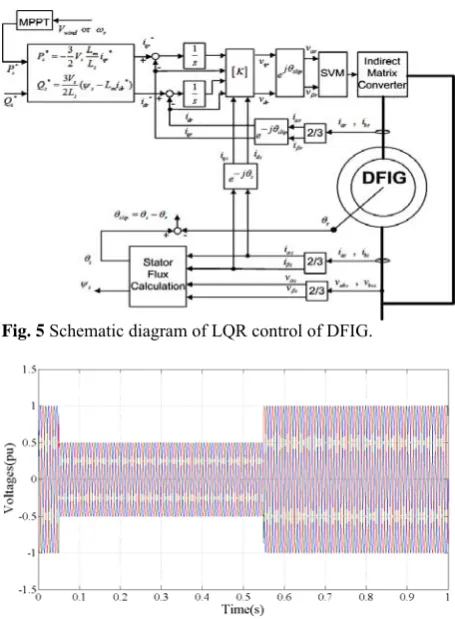
The schematic diagram of the optimal LQR control of the DFIG is shown in Fig. 5.
Table 1 DFIG eigenvalues.
Eigenvalues Damping Freq. (rad/s)
-20.9+34.5i 0.519 40.3
-20.9-34.5i 0.519 40.3
-25.9+312i 0.083 314
-25.9-312i 0.083 314
Table 2. Closed loop eigenvalues applying LQR.
Eigenvalues Damping Freq. (rad/s)
-30.5+18.8i 0.852 35.9
-30.5-18.8i 0.852 35.9
-44+56.9i 0.612 71.9 -44-56.9i 0.612 71.9
-25.9+312i 0.083 314
-25.9-312i 0.083 314
6 Simulation Results
In this section the performance of a DFIG wind turbine is simulated under fault conditions. Parameters of the studied system are provided in Appendix. Simulations are carried out in MATLAB/SIMULINK environment. To simulate the fault condition, at t=0.05 s the grid voltages are dropped to 0.5 pu for 0.5 s as shown in Fig. 6. Fig. 7 shows the rotor currents in this case without any protection. For such a severe voltage dip, the rotor currents are increased to 2.3 pu. In the absence of any protecting method, these high currents can damage the IGBT switches of the IMC. The simulations are carried out to compare the damping and transient stability of the WT with DFIG using the proposed LQR and the conventional PI controllers. To protect the IMC from large fault currents the crowbar is used. It is shown in [4] that the optimal value of a crowbar can be in the range of 50Rr-150Rr considering
several parameters. In the present study the value of 100Rr is assigned to crowbar. The crowbar activation
signal is obtained from comparison of rotor currents with a threshold value. In this simulation the threshold
value is set to 1.4 pu. When the rotor current is greater than the threshold value, the crowbar is activated.
The rotor currents and the crowbar activation signals using the proposed LQR and conventional PI controllers are shown in Fig. 8 and Fig. 9 respectively. It is clear from these figures that in case of LQR the amplitudes of currents are considerably reduced after fault clearance in compare with those of PI controller. The crowbar activation signal reveals that, in contrary with PI controller, in case of proposed LQR controller, the crowbar is not activated after fault clearance. It implies that the transient performance of the system is greatly improved. In addition, in this case the total activation time of crowbar is reduced from 50ms to about 17ms which translates 66% reduction.
As was mentioned in section 2 according to the Danish grid code, wind turbines must remain connected to grid following occurrence of grid faults. Moreover, they must also inject reactive current after 100 ms to help the grid for voltage recovery. In order to meet these new LVRT standards, during fault the references of the active and reactive powers are set as 0.0 pu and 1.0 pu, respectively. As stated in section 4, the reactive power of the DFIG is proportional to d-axis component of the rotor space current.
The reactive current of the DFIG with PI controller and the LQR controller under the fault is depicted in Fig. 10. As can be seen, injection of 1.0 pu reactive current is realized in comply with LVRT standard.
Fig. 5 Schematic diagram of LQR control of DFIG.
Fig. 6 Grid voltages.
Fig. 7 Rotor currents in fault condition, with conventional PI controller.
(a)
(b)
Fig. 8 The rotor currents and crowbar activation signal in fault
condition using Conventional PI.
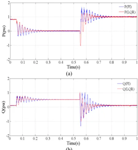
The active and reactive power variations of DFIG during fault for two methods are also shown in Fig. 11. As the reference frame is aligned with the stator flux the active and reactive powers are proportional to the q-axis current (iqr) and the d-axis current (idr) of rotor
respectively. Although these current references are set to 0.0 and 1.0 pu respectively to satisfy the LVRT requirement, the variation of powers is significant as demonstrated in Fig. 11. This arises from severe variations of generator terminal voltage during faults. Furthermore, comparison of two cases in Fig. 11 reveals that the power transient performance is improved in case of the LQR controller regarding the level of oscillations.
(a)
(b)
Fig. 9 The rotor currents and crowbar activation signal in fault
condition using proposed LQR.
Fig. 10 D-axis component of Rotor current in fault condition.
(a)
(b)
Fig. 11 The active and reactive power in two modes.
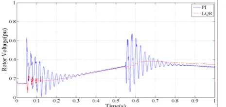
Fig. 12 Required rotor voltage.
The required control effort i.e. the rotor voltage is shown in Fig. 12 for both cases. It is obvious that the rotor voltage is quite smoother and smaller in case of the LQR controller. Therefore, the LQR controller can dampen the power oscillations and improve the transient performance of the DFIG system.
7 Conclusion
In this paper an optimal LQR controller is used to control the rotor currents of the DFIG based WT excited by an indirect matrix converter. Optimization of the weighting matrices of the LQR is performed using the GA technique to achieve the desired closed loop eigenvalues. The optimal LQR controller makes the activation time of the crowbar much shorter in compare with PI controller during the fault and thereafter. The proposed scheme also makes the required rotor voltage smaller and smoother. Furthermore, the transient performance of the DFIG wind turbines is promoted through increasing the system damping. Consequently, by using the LQR controller the LVRT capability is greatly improved and the new standards are well satisfied. Simulation results confirm the efficiency of the proposed controller.
Appendix
Parameters of the studied system are as follows. Wind turbine: DFIG:
Pnom=1.5MW Pnom=1.5MW , Vnom=690V
Base Wind Speed=12m/s fnom=50Hz , R =10.3ms 2
Moment of inertia: 1.2 Mkg.m R =8.28m , L =0.2801mHr ls Gearbox Ratio:n /n1
Ω
Ω
=1/100 L =0.1177mH , L =26.96mH
2 lr m
2 P=6 , J=116 Kg.m
References
[1] Friedli T., Kolar J. W., Rodriguez J. and Wheeler P. W., “Comparative Evaluation of Three-Phase AC–AC Matrix Converter and Voltage DC-Link Back-to-Back Converter Systems”, IEEE Trans. on Industrial Electronics, Vol. 59, No. 12, pp. 4487-4510, Dec. 2012.
[2] Tsili M. and Papathanassiou S., “A review of grid code technical requirements for wind farms”, Trans. on Renewable Power Generation, Vol. 3, No. 3, pp.308-332, Sep. 2009.
[3] Niiranen J., “Voltage dip ride through of a doubly fed generator equipped with active crowbar”, Proceeding Nordic Wind Power Conference, 2004.
[4] Lohde R., Jensen S., Knop A. and Fuchs F. W., “Analysis of three phase grid failure and Doubly Fed Induction Generator ride-through using crowbars”, European Conference on Power Electronics and Applications, pp.1-8, Sep. 2007. [5] Peng L., Francois B. and Yongdong Li,
“Improved Crowbar Control Strategy of DFIG Based Wind Turbines for Grid Fault Ride-Through”, Applied Power Electronics Conference and Exposition, Twenty-Fourth Annual IEEE APEC 2009. pp. 1932-1938, Feb. 2009.
[6] Wei Z., Peng Z. and Yikang H., “Analysis of the by-pass resistance of an active crowbar for doubly-fed induction generator based wind turbines under grid faults”, International Conference on Electrical Machines and Systems, ICEMS., pp. 2316-2321, Oct. 2008.
[7] Hansen A. D. and Michalke G., “Fault ride-through capability of DFIG wind turbines”, Renewable Energy, Vol. 32, pp. 1594-1610, 2007. [8] Dawei X., Li R., Tavner P. J. and Yang S.,
“Control of a doubly fed induction generator in a wind turbine during grid fault ride-through”, IEEE Trans. on Energy Conversion, Vol. 21, No. 3, pp. 652-662, Sep. 2006.
[9] Rahimi M. and Parniani M., “Efficient control scheme of wind turbines with doubly fed induction generators for low-voltage ride-through capability enhancement”, IET Trans. on Renewable Power Generation, Vol. 4, No. 3, pp. 242-252, May 2010.
[10] Rahimi M. and Parniani M., “Grid-fault ride-through analysis and control of wind turbines with doubly fed induction generators”, Electric Power Systems Research, Vol. 80, pp. 184-195, 2010.
[11] Lima F. K. A., Luna A., Rodriguez P., Watanabe E. H. and Blaabjerg F., “Rotor Voltage Dynamics in the Doubly Fed Induction Generator During Grid Faults”, IEEE Trans. on Power Electronics, Vol. 25, No. 1, pp. 118-130, Jan. 2010.
[12] Rathi M. R. and Mohan N., “A novel robust low voltage and fault ride through for wind turbine application operating in weak grids”, 31-st Annual Conference of IEEE Trans. on Industrial Electronics Society, IECON, pp. 6-10, Nov. 2005. [13] Yi Z., Bauer P., Ferreira J. A. and Pierik J.,
“Operation of Grid-Connected DFIG Under Unbalanced Grid Voltage Condition”, IEEE
Trans. on Energy Conversion, Vol. 24, No. 1, pp. 240-246, Mar. 2009.
[14] Li D. and Zhang H., “A combined protection and control strategy to enhance the LVRT capability of a wind turbine driven by DFIG”, 2nd IEEE International Symposium on Power Electronics for Distributed Generation Systems (PEDG), pp. 703-707, June 2010.
[15] Abbey C. and Joos G., “Short-term energy storage for wind energy applications”, Fourtieth IAS Annual Meeting. Conference Record of the Industry Applications Conference, Vol. 3, pp. 2035- 2042, Oct. 2005.
[16] Abbey C., Wei L., Owatta L. and Joos G., “Power Electronic Converter Control Techniques for Improved Low Voltage Ride Through Performance in WTGs”, 37th IEEE Power Electronics Specialists Conference, PESC '06, pp. 1-6, June 2006.
[17] Erlich I., Wrede H. and Feltes C., “Dynamic Behavior of DFIG-Based Wind Turbines during Grid Faults”, Power Conversion Conference- Nagoya, PCC '07, pp. 1195-1200, April 2007. [18] Reyes E., Pena R., Cardenas R., Wheeler P.,
Clare J. and Blasco-Gimenez R., “Application of indirect matrix converters to variable speed doubly fed induction generators”, IEEE Power Electronics Specialists Conference, PESC 2008, pp. 2698-2703, June 2008.
[19] Amini J., Kazemzahed R. and Madadi Kojabadi H., “Performance enhancement of indirect matrix converter based variable speed Doubly-Fed induction generator”, Power Electronic & Drive Systems & Technologies Conference (PEDSTC), pp. 450-455, Feb. 2010.
[20] Aghasi M., Khaburi D. A., Faraji V. and Behni H. “A Comparative Study on Predictive and ISVM Direct Torque Control Methods for a Doubly Fed Induction Machine Fed by an Indirect Matrix Converter” Iranian Journal of Electrical & Electronic Engineering, Vol. 8, No. 2, pp. 138-145, June 2012.
[21] Reyes E., Pena R., Cardenas R., Clare J. and Wheeler P., “Control of a Doubly-fed Induction Generator with an Indirect Matrix Converter with changing DC voltage”, 2010 IEEE International Symposium on Industrial Electronics (ISIE), pp. 1230-1235, July 2010.
[22] Wenlang D., Zhiyong C., Liming Z. and Yu Y., “Research on the performance of low voltage ride-through for doubly fed induction generator excited by two-stage matrix converter”, Power Electronics and Motion Control Conference, IPEMC '09. IEEE 6th International, pp. 638-643, May 2009.
[23] Hasanzadeh A., Edrington C. S. and Mokhtari H., “Optimal tuning of linear controllers for power electronics/power systems applications”, Electric
Power Systems Research, Vol. 8, pp. 2188-2197, 2011.
[24] Vieira J. P. A., Nunes M. V. A., Bezerra U. H., do Nascimento A. C., “Designing optimal controllers for doubly fed induction generators using a genetic algorithm”, IET Trans. on Generation, Transmission & Distribution, Vol. 3, No. 5, pp. 472-484, May 2009.
[25] Feng W., Xiao-Ping Z., Ping J. and Sterling M. J. H., “Decentralized Nonlinear Control of Wind Turbine With Doubly Fed Induction Generator”, IEEE Trans. on Power Systems, Vol. 23, No. 2, pp. 613-621, May 2008.
[26] Muhando E. B., Senjyu T., Uehara A., Funabashi T. and Chul-Hwan K., “LQG Design for Megawatt-Class WECS With DFIG Based on Functional Models' Fidelity Prerequisites”, IEEE Trans. on Energy Conversion, Vol. 24, No. 4, pp. 893-904, Dec. 2009.
[27] Michalke G., “Variable Speed Wind Turbines- Modeling, Control, and Impact on Power Systems”, PhD Thesis, Riso National Laboratory, 2008.
[28] Kalantar M. and Sedighizadeh M. “Reduced order model for doubly output induction generator in wind park using integral manifold theory” Iranian Journal of Electrical & Electronic Engineering, Vol. 1, No. 1, pp. 41-48, Jan. 2005.
[29] Wei L. and Lipo T. A., “A novel matrix converter topology with simple commutation”, IEEE Industry Applications Conference, Thirty-Sixth IAS Annual Meeting, Vol. 3, pp. 1749-1754, 2001.
[30] Barakati S. M., “Modeling and Controller Design of a Wind Energy Conversion system Including a Matrix Converter”, PhD Thesis, University of Waterloo, 2008.
[31] Zahiri S. H., Rajabi Mashhadi H. and Seyedin S. A., “Intelligent and Robust Genetic Algorithm Based Classifier”, Iranian Journal of Electrical & Electronic Engineering, Vol. 1, No. 3, pp. 1-9, July 2005.
[32] Soleimanpour M., Talebi S. and Azadi-Motlagh H., “A Novel Technique for Steganography Method Based on Improved Genetic Algorithm Optimization in Spatial Domain”, Iranian Journal of Electrical & Electronic Engineering, Vol. 9, No. 2, pp. 67-75, June 2013.
[33] Daneshfar F., Bevrani H. and Mansoori F., “Load-Frequency Control: A GA Based Bayesian Networks Multi-Agent System”, Iranian Journal of Electrical & Electronic Engineering, Vol. 7, No. 2, pp. 141-148, June 2011.
Ahmad Khajeh was born in Zabol,
Iran in 1982. He received the B.Sc. degree in electronic engineering and the M.Sc. degree in power engineering from the Sistan and Baluchestan Universtity and Amirkabir University of Technology, Iran, in 2004 and 2007 respectively. He is currently a Ph.D. student at the Ferdowsi University of Mashhad. His research interests are power electronics, electric drives and wind power.
Reza Ghazi (M’90) was born in
Semnan, Iran in 1952. He received his B.Sc., degree (with honors) from Tehran University of Science and Technology, Tehran, Iran in 1976. In 1986 he received his M.Sc. degree from Manchester University, Institute of Science and Technology (UMIST) and the Ph.D. degree in 1989 from University of Salford UK, all in electrical engineering. Following receipt of the Ph.D. degree, he joined the faculty of engineering Ferdowsi University of Mashhad, Iran as an Assistant Professor of electrical engineering. He is now Professor of Electrical Engineering in Ferdowsi University of Mashhad, Iran. His main research interests are reactive power control, FACTS devices, application of power electronic in power systems, distributed generation, restructured power systems control and analysis. He has published over 100 papers in these fields including three books.