International Journal of Engineering
J o u r n a l H o m e p a g e : w w w . i j e . i r
Reduction of Odometry Error in a Two Wheeled Differential Drive Robot
T. Mathavaraj Ravikumar* a, R. Saravanan b
a Department of Mechanical Engineering, United Institute of Technology, Coimbatore-641020, India b Principal, JCT College of Engineering and Technology, Coimbatore-641105, India
P A P E R I N F O
Paper history: Received 09 April 2013
Received in revised form 25 May 2013 Accepted 22 August 2013
Keywords: Mobile Robot Odometry Relative Localization Response Surface Methodology Excel Solver
A B S T R A C T
Pose estimation is one of the vital issues in mobile robot navigation. Odometry data can be fused with absolute position measurements to provide better and more reliable pose estimation. This paper deals with the determination of better relative localization of a two wheeled differential drive robot by means of odometry by considering the influence of parameters, namely weight, velocity, wheel perimeter and tyre width. Experiments have been conducted based on central composite rotatable design matrix. A mathematical model has been developed for the robot with the help of MINITAB software. An optimum range and condition for minimum odometry error were obtained by using Response Surface Methodology (RSM) and Excel (XL) Solver respectively.
doi:10.5829/idosi.ije.2014.27.03c.02
NOMENCLATURE
DL: Linear distance travelled by left wheel
DR: Linear distance travelled by right wheel
DOF: Degree of freedom
1. INTRODUCTION1
Mobile robots represent an evolution of robots, since they can move freely in dynamic environments. The proliferation of mobile robots is subjected to tackling two major problems, localization and path planning. The objective of localization is to determine the position of a mobile robot in its environment, given a map of the environment and local sensorial data. Pose estimation of robot has been known as one of the most fundamental problems in mobile robotics [1-3]. Two basic pose estimation methods (absolute and relative positioning) are widely employed in mobile robots [4-6]. Odometry is the mostly used navigation method for relative positioning of mobile robot because it provides good accuracy, is inexpensive, and allows very high sampling rates [7]. Absolute positioning methods usually rely on navigation beacons, active or passive landmarks, map
1*Corresponding Author Email: [email protected] (T.
Mathavaraj Ravikumar)
matching and satellite based navigation signals, but none of these existing methods are well designed. Another approach to the pose determination of mobile robots is based on inertial navigation with gyros and accelerometers. The experimental results acquired by the researchers [8, 9] indicate that this approach is not advantageous. Gyros can be more accurate and costly but they provide information only on the rate of rotation of a robot [10]. This sort of problem does not exist with electronic compasses that measure the orientation of the robot relative to the magnetic field of the earth.
However, electronic compasses are not recommended for indoor applications due to the large distortions of the magnetic field near power lines or steel structures [2].
Many researchers have concentrated upon the accurate calibration of odometry [11, 12], measuring errors in odometry [13] and development of models for minimizing the odometry errors [14-16] in wheeled robots. In addition, researchers have focused on the optimum path planning [17, 18] and stability analyses in mobile robots [19-22]. Robot’s movement and abilities on particular terrain are affected by many factors like geometry and type of locomotion system (wheeled, tracked, hybrid, legged, jumping), properties of effectors (e.g. tyre type for wheeled robots), mass properties of a robot and constraints resulting from characteristics of drives [23, 24].
From the literature, it is observed that the major research works have been focused on the development of odometry error models, stability analyses and path planning for mobile robots. Very few researchers have considered the effect of parameters like weight, velocity and geometry of wheels for mobile robot in the determination of relative localization using odometry. In this paper, a mathematical model for odometry error of a two wheeled differential drive robot has been developed. An optimum range and condition were obtained through RSM and XL Solver respectively.
2. TWO WHEELED DIFFERENTIAL DRIVE ROBOT
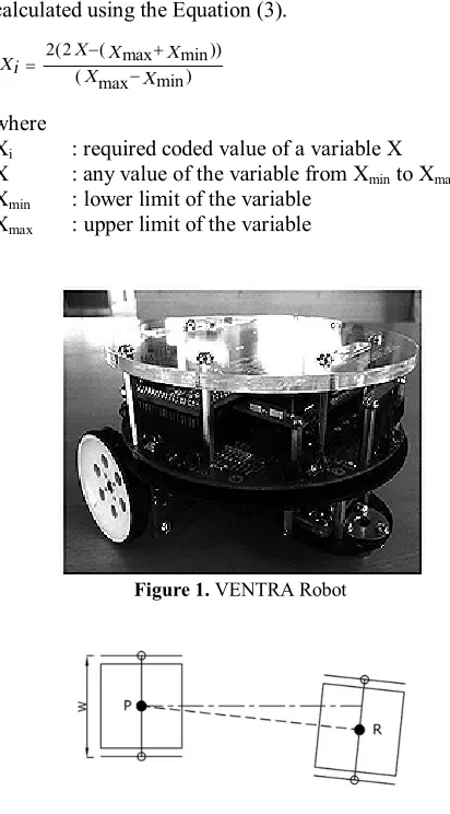
A two wheeled differential drive robot “VENTRA”
shown in Figure 1 was employed for conducting experiments in this study. The robot was driven in an indoor environment for a distance of 2 m in a straight line path. An evenly paved cement concrete floor was used as terrain which normally minimizes the chance of non-systematic errors such as wheel slippage, interaction with external bodies and travel over unexpected objects on the floor.
The self weight of the robot is 1.2 kg and the distance between two wheels (W) is 120 mm. The maximum speed of the robot is 200 mm/s. Two encoder wheels with encoders are used to calculate the linear displacement of each wheel. The new orientation of the robot can be estimated from difference in encoder counts, diameter of the wheels and distance between the wheels.
2. 1. Calculation of Odometry Error Odometry is a measuring method of wheel rotation as a function of time. If the two wheels of the robot are joined to a common axle, orientation of the centre of the axle relative to the previous orientation can be determined from odometry measurements on both wheels. In actual practice, optical encoders mounted on both wheels feed discretised wheel increment information to the controller, which in turn used to calculate the robot’s state using geometric equations. The wheel base (W) of the robot is the space between the contact points of two rear wheels. The center of the robot with respect to odometry is the midpoint between these two contacts. To calculate the variation in position and orientation of the robot with respect to starting point (P) across a given span of time, linear distance DR and DL of each wheel
traveled (computed from number of ticks of the encoders and diameter of the wheels) and wheel base (W) are substituted in the following Equation (1). The new orientation (R) in radians shown in Figure 2 is calculated by
R = P + (DR- DL) / W (1)
3. RESPONSE SURFACE METHODOLOGY
Response surface methodology (RSM) is one of the effective methods of analyzing the result of a factorial experiment. Odometry error (Oe) can be treated as output response and expressed as functions of parameters namely weight (A), velocity (B), wheel perimeter (C), tyre width (D) as indicated in Equation (2).
(
)
( ) , , , e
Odometry error Oe =f A Biu iuCiuDiu + u (2)
where, ϕ=response surface, eu=residual, u=number of
observations in the factorial experiment and iu represents level of the ith factor in the uth observation.
When the mathematical form of ϕ is unknown, it can be approximated by polynomials satisfactorily within the experimental region in terms of parameter variables. The ranges of all the parameters were fixed by conducting trial runs. This was performed by varying one of the parameters while keeping the rest of them as constant values. The upper and lower limits of a given parameter were coded as (+2) and (-2), respectively. The coded values for intermediate values were calculated using the Equation (3).
2(2 ( max min))
)
( max min
X X X
Xi X
X
- +
= - (3)
where
Xi : required coded value of a variable X
X : any value of the variable from Xmin to Xmax
Xmin : lower limit of the variable
Xmax : upper limit of the variable
Figure 1. VENTRA Robot
The intermediate values were coded as -1, 0, and 1. The parameters with their limits and notations are given in Table 1. The design matrix chosen to conduct the experiments was a five level, four factor central composite rotatable design consisting of 31 sets of coded conditions and comprising of a half replication 24=16 factorial design plus 8 star points and 7 centre
points as given in Table 2. All parameters at the intermediate level (0) constitute the centre points while the combination of each parameter at either its lower level (-2) or its higher level (+2) with the other two parameters at the intermediate level constitute the star points. Thus, the 31 experimental runs allow the
estimation of linear, quadratic, and two way interactive effects of the parameters on odometry error [25].
TABLE 1. Parameters and their levels
Parameters & Notations Units Levels
-2 -1 0 1 2
Weight (A) kg 0 0.2 0.4 0.6 0.8
Velocity (B) mm/s 75 100 125 150 175 Wheel perimeter (C) mm 126 157 188 220 252
Tyre width (D) mm 4 8 12 16 20
TABLE 2. Experimental design – Central composite rotatable design matrix
Exp. No. Control parameters Odometry error (rad) % error
A B C D Measured Predicted
1 -1 -1 -1 -1 0.039215 0.03929 -0.19
2 1 -1 -1 -1 0.019635 0.01935 1.48
3 -1 1 -1 -1 0.036875 0.03697 -0.25
4 1 1 -1 -1 0.016335 0.01605 1.76
5 -1 -1 1 -1 0.035255 0.03420 3.01
6 1 -1 1 -1 0.019415 0.01893 2.52
7 -1 1 1 -1 0.037675 0.03739 0.76
8 1 1 1 -1 0.020845 0.02114 -1.43
9 -1 -1 -1 1 0.035285 0.03475 1.53
10 1 -1 -1 1 0.024035 0.02430 -1.10
11 -1 1 -1 1 0.032505 0.03298 -1.45
12 1 1 -1 1 0.020735 0.02155 -3.95
13 -1 -1 1 1 0.028875 0.02914 -0.91
14 1 -1 1 1 0.023705 0.02337 1.43
15 -1 1 1 1 0.032835 0.03288 -0.15
16 1 1 1 1 0.026235 0.02614 0.37
17 -2 0 0 0 0.041305 0.04164 -0.81
18 2 0 0 0 0.015015 0.01495 0.45
19 0 -2 0 0 0.026835 0.02777 -3.47
20 0 2 0 0 0.028875 0.02821 2.29
21 0 0 -2 0 0.033275 0.03284 1.31
22 0 0 2 0 0.031625 0.03233 -2.22
23 0 0 0 -2 0.022165 0.02301 -3.81
24 0 0 0 2 0.024035 0.02346 2.40
25 0 0 0 0 0.022935 0.02301 -0.34
26 0 0 0 0 0.023375 0.02301 1.54
27 0 0 0 0 0.022715 0.02301 -1.32
28 0 0 0 0 0.024035 0.02301 4.25
29 0 0 0 0 0.022165 0.02301 -3.83
30 0 0 0 0 0.022935 0.02301 -0.34
4. EXCEL (XL) SOLVER
Solver is a powerful optimization tool, bundled with Microsoft Excel and is widely used for optimizing nonlinear engineering models. Optimization in Microsoft Excel begins with an ordinary spreadsheet. The solver finds a maximum or minimum or specified value of a target cell by varying the values in one or several changing cells [26]. It accomplishes this by means of an iterative process, beginning with trial values of the coefficients. The value of each coefficient is changed by a suitable increment, the new value of the function is calculated and the change in the value of the function is used to calculate improved values for each of the coefficients. The process is repeated until the desired result is obtained. The solver uses gradient methods to find the optimum set of coefficients.
5. RESULTS AND DISCUSSION
5. 1. Optimum Range through RSM The direct effects of various parameters like weight, velocity, wheel perimeter and tyre width on odometry error were analyzed by conducting experiments based on Response Surface Methodology (RSM) and the results are shown in graphs. The influence of particular parameter in different levels over odometry error was analyzed by considering other parameters at the mid level and the optimum range of each parameter was also discussed in the following sections.
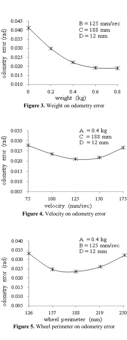
5. 1. 1. Weight From Figure 3, it was observed that the odometry error decreased with the increase of weight upto 0.6 kg. Also, it was observed that there was no significant change in the odometry error beyond it. So, the odometry error could be lesser between 0.6 kg and 0.8 kg. The increase in weight considerably reduces the wheel slippage and tottering of robot that leads to less odometry error.
5. 1. 2. Velocity From Figure 4, it was noted that when the velocity increased from 75 mm/sec, the odometry error decreased significantly and started increasing after certain level. So, it is clearly understood that the error is minimum between 125 mm/sec and 150 mm/sec. When the robot is moving with slower velocity in practical conditions, the possibilities of wheel distortions, vibrations and wheel slippage are appreciably less which causes very minimal odometry error.
5. 1. 3. Wheel Perimeter From Figure 5, it was noticed that the odometry error decreased when the wheel perimeter increased from 126 mm to 157 mm and increased when perimeter increased further. It is clear
that the odometry error is lesser between 157 to 188 mm of wheel perimeter. The wheel perimeter should not be very high nor very low for the reduction of odometry error. The lesser and larger perimeters of wheel lead to the possibilities for wheel turn at maximum speeds and jerks at slower speeds respectively which cause deviation from linear path.
Figure 3. Weight on odometry error
Figure 4. Velocity on odometry error
5. 1. 4. Tyre Width From Figure 6,it was observed that there was a decrease in odometry error when the tyre width varied from 4 mm to 8 mm and further increased with the increase in width. So, it is evident that the minimum odometry error seems to be in the range 8 - 12 mm of thickness. The lesser contact area of tyre on the floor due to smaller width provides the accurate wheel base for the odometry calculation that leads to minimal odometry error.
5. 2. Optimum Condition through XL Solver
5. 2. 1. Development of Mathematical Model The general form of a quadratic polynomial which gives the relation between response surface ‘Y’ and the process variable ‘X’ is given in Equation (4).
0 4 4 2 4
Y
1 1
= +a åi=aiXi+åi=aiiXi+åi j< aijX Xi j (4)
where ao=constant, ai=linear term coefficient,
aii=quadratic term coefficient and aij=interaction term
coefficient. The values of the coefficients of the polynomials were calculated using the multiple regression method. A statistical analysis software MINITAB was used to calculate the values of these coefficients. The second order mathematical model was developed for odometry error (Oe) as given in Equation (5).
Oe = 0.023014 – 0.006673A + 0.000112B –
0.000128C + 0.000112D + 0.00132A2 + 0.001244B2 + 0.002392C2 + 0.000055D2 – 0.000244AB + 0.001169AC + 0.002375AD + 0.001379BC + 0.000138BD – 0.000128CD
(5)
where
A : Weight in kg
B : Velocity of robot in mm/s C : Wheel perimeter in mm D : Tyre width in mm
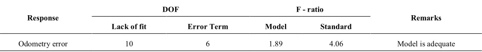
The adequacy of the model is tested using the analysis of variance (ANOVA). As per the ANOVA technique [27], the model can be considered to be adequate if the calculated value of F-ratio of the model should not exceed the standard tabulated value of F-ratio for a desired level of confidence (95%). From the values in Table 3, it can be deduced that the current model is adequate. It is evident from the Table 2 that the error between the experimental and predicted values is less than 5%.
5. 2. 2. XL Solver Result The optimum range of each parameter was found for minimum odometry error through RSM. In order to obtain optimum level of each parameter for minimal odometry error, XL solver tool was used in this study. The mathematical model given in Equation (5) was used as the target function with a condition of minimization and the constraints were set for all control parameters. Newton method was selected to search an optimal point. An optimized odometry error (0.01424 rad) was found at optimum parametric condition (Coded values: A: 2, B: 0.151126, C: -0.4619, D: -1.00175 and corresponding decoded values: A: 0.8 kg, B: 128.8 mm/sec, C: 173.68 mm, D: 8 mm). XL solver settings and results are shown in Figures 7 and 8.
Figure 6. Tyre width on odometry error
Figure 7. XL solver setting
TABLE 3: Adequacy of the model
Response DOF F - ratio Remarks
Lack of fit Error Term Model Standard
Figure 8. XL solver result
5. 2. 3. Confirmatory Test for XL Solver Optimum Condition A confirmatory experiment was conducted for the optimum condition (A=0.8 kg; B=129 mm/sec; C=174 mm and D=8 mm), and odometry error (0.01405 rad) was obtained, which is very close to the XL solver result.
6. CONCLUSION
In this work, experiments were conducted based on central composite rotatable design matrix. A mathematical model was developed for the two wheeled differential drive robot using MINITAB software. Response Surface Methodology and XL Solver tool were employed to determine the optimum range and optimum condition for the better relative localization i.e. minimum odometry error. The optimum range and condition of parameters were found as follows.
Parameter Optimum range by RSM Optimum condition by XL solver
Weight 0.6 – 0.8 kg 0.8 kg
Velocity 125 – 150 mm/sec 128.8 mm/sec Wheel
perimeter 157 – 188 mm
173.68 mm
Tyre width 8 – 12 mm 8 mm
The optimum condition was checked through the confirmation experiment. From this study, this optimum parametric setting is suggested for minimal odometry error in a two wheeled differential drive robot.
7. REFERENCES
1. Lategahn, J., Kuenemund, F. and Roehrig, C., "Mobile robot localization using wlan, odometry and gyroscope data",
International Journal of Computing, Vol. 9, No. 1, (2010),
22-30
2. Byrne, R., Klarer, P. and Pletta, J., "Techniques for autonomous navigation", (1992).
3. Hoseinnezhad, R., Moshiri, B. and Asharif, M., "A new approach to self-localization for mobile robots using sensor data fusion", International Journal of Engineering, Vol.15, No. 2, (2002) 145-156
4. Hollingum, J., "Caterpillar make the earth move: Automatically: The first company to achieve success in marketing free-ranging guided vehicles", Industrial Robot: An International Journal, Vol. 18, No. 2, (1991), 15-18.
5. Chenavier, F. and Crowley, J. L., "Position estimation for a mobile robot using vision and odometry", in Robotics and Automation, IEEE International Conference on, IEEE, (1992), 2588-2593.
6. Evans, J. M., "Helpmate: An autonomous mobile robot courier for hospitals", in Intelligent Robots and Systems' 94.'Advanced Robotic Systems and the Real World', IROS'94. Proceedings of the IEEE/RSJ/GI International Conference on, IEEE. Vol. 3, (1994), 1695-1700.
7. Borenstein, J., "Experimental results from internal odometry error correction with the omnimate mobile robot", Robotics and Automation, IEEE Transactions on, Vol. 14, No. 6, (1998), 963-969.
8. Borenstein, J. and Feng, L., "Measurement and correction of systematic odometry errors in mobile robots", Robotics and Automation, IEEE Transactions on, Vol. 12, No. 6, (1996), 869-880.
9. Barshan, B. and Durrant-Whyte, H. F., "Orientation estimate for mobile robots using gyroscopic information", in Intelligent Robots and Systems' 94.'Advanced Robotic Systems and the Real World', IROS'94. Proceedings of the IEEE/RSJ/GI International Conference on, IEEE. Vol. 3, (1994), 1867-1874. 10. Komoriya, K. and Oyama, E., "Position estimation of a mobile
robot using optical fiber gyroscope (ofg)", in Intelligent Robots and Systems' 94.'Advanced Robotic Systems and the Real World', IROS'94. Proceedings of the IEEE/RSJ/GI International Conference on, IEEE. Vol. 1, (1994), 143-149.
11. Krantz, D. and Gini, M., "Non-uniform dead-reckoning position estimate updates", in Robotics and Automation, IEEE International Conference on, IEEE. Vol. 3, (1996), 2061-2066. 12. Lee, K., Jung, C. and Chung, W., "Accurate calibration of
kinematic parameters for two wheel differential mobile robots",
Journal of Mechanical Science and Technology, Vol. 25, No.
6, (2011), 1603-1611.
13. Kleeman, L., "Odometry error covariance estimation for two wheel robot vehicles", Intelligent Robotics Research Centre, Department of Electrical and Computer Systems Engineering,
Monash University, Tech. Rep. MECSE-95-1, (1995).
14. Borenstein, J. F., L., "Umb mark - a method for measuring, comparing and correcting dead-reckoning errors in mobile robots", Technical Report UM-MEAM-94-22 University of
Michigan, (1995).
15. Ojeda, L. and Borenstein, J., "Methods for the reduction of odometry errors in over-constrained mobile robots",
Autonomous Robots, Vol. 16, No. 3, (2004), 273-286.
16. Korayem, M., Nakhai, A. and Rostam, T. B., "Design, modelling and errors measurement of wheeled mobile robots", The
International Journal of Advanced Manufacturing
Technology, Vol. 28, No. 3-4, (2006), 403-416.
17. Shen, Z.-h., Zhao, Y.-k. and Wu, W.-w., "Niche pseudo-parallel genetic algorithms for path optimization of autonomous mobile robot", Journal of Shanghai University (English Edition), Vol. 10, No. 5, (2006), 449-453.
with joint limit constraints", in Robotics and Biomimetics (ROBIO), International Conference on, IEEE. (2011), 596-601. 19. Eghtesad, M. and Necsulescu, D. S., "Study of the internal
dynamics of an autonomous mobile robot", Robotics and
Autonomous Systems, Vol. 54, No. 4, (2006), 342-349.
20. Wang, C., Liang, Z. and Jia, Q., "Dynamic feedback robust stabilization of nonholonomic mobile robots based on visual servoing", Journal of Control Theory and Applications, Vol. 8, No. 2, (2010), 139-144.
21. Cai, J. and Ruan, X., "Bionic autonomous learning control of a two-wheeled self-balancing flexible robot", Journal of Control
Theory and Applications, Vol. 9, No. 4, (2011), 521-528.
22. Cai, Y., Zhan, Q. and Xi, X., "Path tracking control of a spherical mobile robot", Mechanism and Machine Theory, Vol. 51, (2012), 58-73.
23. Trojnacki, M., "Analysis of influence of drive system configurations of a four wheeled robot on its mobility", Journal
of Automation, Mobile Robotics & Intelligent Systems, Vol. 6,
No. 4, (2012), 65-70.
24. Korayem, M., Peydaie, P. and Azimirad, V., "Investigation on the effect of different parameters in wheeled mobile robot error",
International Journal of Engineering, Vol.20, No.2, (2007)
195-210.
25. Montgomery, D. C., "Design and analysis of experiments", Wiley New York, Vol. 7, (1984).
26. Senthil, P. and Amirthagadeswaran, K., "Enhancing wear resistance of squeeze cast ac2a aluminum alloy", International
Journal of Engineering-Transactions A: Basics, Vol. 26, No.
4, (2012), 365.
Reduction of Odometry Error in a Two Wheeled Differential Drive
Robot
TECHNICAL NOTE
T. Mathavaraj Ravikumar a, R. Saravanan b
a Department of Mechanical Engineering, United Institute of Technology, Coimbatore-641020, India b Principal, JCT College of Engineering and Technology, Coimbatore-641105, India
P A P E R I N F O
Paper history: Received 09 April 2013
Received in revised form 25 May 2013 Accepted 22 August 2013
Keywords: Mobile Robot Odometry Relative Localization Response Surface Methodology Excel Solver
هﺪﯿﮑﭼ
ﺖﯿﻌﺿوﻦﯿﻤﺨﺗ زاﯽﮑﯾ
ﻢﻬﻣتﺎﻋﻮﺿﻮﻣ رد
يﺮﺑوﺎﻧ تﺎﺑور ﺖﺳاهاﺮﻤﻫﻦﻔﻠﺗ
.
يﺎﻫهداد يﺮﺘﻣودوا ﯽﻣار ﺎﺑناﻮﺗ يﺮﯿﮔهزاﺪﻧا
ﻖﻠﻄﻣﺖﯿﻌﻗﻮﻣ هدﺮﮐﻖﯿﻔﻠﺗ
و دروآﺮﺑ وﺮﺘﻬﺑ دروآﺖﺳدﻪﺑارﺖﯿﻌﺿوارﺮﺗدﺎﻤﺘﻋاﻞﺑﺎﻗ
.
ﻦﯾا ﻪﺑﻪﻟﺎﻘﻣ ﻦﯿﯿﻌﺗ ﻞﺤﻣ ﯽﺒﺴﻧ ﺮﺘﻬﺑ زا
تﺎﺑورﮏﯾ ود ﻞﯿﺴﻧاﺮﻔﯾد خﺮﭼ راد زاهدﺎﻔﺘﺳاﺎﺑ ﻦﺘﻓﺮﮔﺮﻈﻧردﺎﺑيﺮﺘﻣودوا
يﺎﻫﺮﺘﻣارﺎﭘﺮﯿﺛﺎﺗ نزو
،ﺖﻋﺮﺳ، ﻂﯿﺤﻣ خﺮﭼ و
ضﺮﻋ ﺮﯾﺎﺗ ﯽﻣ دزادﺮﭘ
.
ﺶﯾﺎﻣزآ سﺎﺳاﺮﺑ ﺲﯾﺮﺗﺎﻣ ﯽﺣاﺮﻃ نﺎﺧﺮﭼ يﺰﮐﺮﻣﺐﮐﺮﻣ ﺖﺳاهﺪﺷمﺎﺠﻧا
.
ﯽﺿﺎﯾرلﺪﻣ ياﺮﺑ
تﺎﺑور
ﮏﻤﮐﺎﺑ راﺰﻓامﺮﻧ
MINITAB
ﺖﺳاهﺪﺷمﺎﺠﻧا
.
هدوﺪﺤﻣ و ﻂﯾاﺮﺷ ياﺮﺑ ﻞﻗاﺪﺣ ردﺎﻄﺧ ﻪﻨﯿﻬﺑيﺮﺘﻣودواﺶﺠﻨﺳ ﻪﺑ
زاهدﺎﻔﺘﺳاﺎﺑﺐﯿﺗﺮﺗ ﺢﻄﺳشور
ﺦﺳﺎﭘ
(RSM)
و ﻞﺴﮐا
(XL)
هﺪﻨﻨﮐﻞﺣ ﺪﻣآﺖﺳدﻪﺑ
.
doi:10.5829/idosi.ije.2014.27.03c.02