Influential Factor in Improving the Seismic Performance of the Kaiser Bolted Bracket
Moment Connection
F. Shahidi * a, F. Nateghi-A b, M. S. Razzaghi c, F. Shahidi d
a Department of Civil Engineering and Surveying, Qazvin Branch, Islamic Azad University, Iran
bInternational Institute of Earthquake Engineering and Seismology of Tehran, Iran cFaculty of Civil Engineering and Surveying, Qazvin Branch, Islamic Azad University, Iran
d Department of Civil Engineering, Islamic Azad University of Takestan, Iran
P A P E R I N F O
Paper history: Received 26 August 2012
Accepted in revised form 18 October 2012
Keywords:
Standard Loading History Near-fault Loading History
Kaiser Bolted Bracket Connection (KBB) Pinch
A B S T R A C T
Following the Northridge earthquake of 1994, a significant number of steel moment resisting structural systems were damaged. Several studies have been conducted to improve the seismic performance of steel structures and specially their beam-to-column connections. One of the proposed connections for special moment-resisting frames included in AISC-358 is Kaiser bolted bracket moment connection, briefly named, KBB. The brackets in these connections are precast steel elements. In this study, the seismic behavior of moment connection KBB has been examined under standard loading history and near-fault loading history according to ATC and FEMA codes. The results show that KBB connection has acceptable seismic performance except for deep beams. In deep beams a high prying force may occurs in upper rows of the bolts. the main reason for such phenomenon is rigidity of the bracket. Moreover use of Tapered Wedge Shims reduces pre-tensioned force in bolts and increases pinch in hysteresis curve of specimens.
11. INTRODUCTION
In the aftermath of the 1994 Northridge, California, earthquake, damage to moment resisting frames connections spawned concern for the reliability of established design and construction procedures [1].
Widespread damage was observed in beam-to-column joints that experienced rotation levels well below the plastic moment capacity of the framing members [1-3]. Failures included non-ductile fractures of the bottom girder flange-to-column flange complete-joint-penetration (CJP), groove welds, cracks in beam flanges and cracks through the column section [2, 3]. After the earthquake, several studies were conducted to improve the seismic performance of moment connections, and a variety of connection were proposed. Tsai and Popov [4] pointed out that the use of an end-plate rib stiffener combined with stronger bolts could significantly improve the behavior of extended end-plate connections under large cyclic loading, which could then be designed to develop the full plastic
*Corresponding Author Email: [email protected] (F. Shahidi)
moment capacity of the beam. They also noticed that the prying forces were reduced by the use of the end-plate rib stiffener. Seradj [5] carried out experiments on eight-bolt stiffened extended beam-to-column end-plate connections under cyclic loading. Results of these experiments revealed that the rigidity of this connection depends on thickness of the end plate and bolt diameter. It was also shown that using thinner end plates and thicker bolts may lead to semi-rigid behavior.
Adey et al. [6] found that using the extension stiffeners increase flexural strength and yield rotation of the connection, as well as its energy dissipation capacity.
Shi et al. [7]tested beam-to-column bolted end-plate connections and welded-plate columns and beams under cyclic loading and concluded that both the end-plate stiffener and the column flange stiffener make an essential contribution to the behavior of end-plate connections. These end plate stiffeners, by ensuring the continuity of the beam web alter the mode of failure of the connection, change the distribution of the forces in the bolts, and consequently influence the mode of deformation of the connection components [8]. All the
International Journal of Engineering
J o u r n a l H o m e p a g e : w w w . i j e . i r
experimental results reviewed so far indicate clearly that the presence of stiffeners in the extended end-plate has a great influence on the behavior of the connections. Thus, the contribution of the stiffeners to mechanical behavior of the connections has to be considered in the design of the whole connection.Azizinamini et al. [9] have experimentally studied the behavior of top-seat bolted angle connections under monotonic and cyclic loadings. Shen and Astaneh-Asl. [10] have experimentally tested the behavior of bolted angle connections and the failure modes and deformation patterns.
Kishi et al. [11] have studied the behavior of these connections using the finite element method. They have evaluated the applicability of a three-parameter relation (proposed by Kishi and Chen) for estimating the behavior of semi-rigid connections. Their FE models included the material nonlinearity for all components and the value of 0.1 was assumed for the friction coefficient. This coefficient is one-third of the usual value (0.33) proposed in the literatures for class “A” types of steel surfaces.
Kasai et al. [12] have experimentally studied the cyclic behavior of a type of welded moment connection similar to the top-seat angle connections with stiffeners and shear tab. This type of connection has moment behavior. They reviewed beams with section depths ranging from 406 mm (16 in) to 914 mm (36 in).
The results showed that bolted connections are capable of providing rigid moment connections with appropriate cyclic plastic rotational capacities in excess of equivalent welded joints, but with the same rigidity as welded connections. The results of these experiments provided a rigorous reference which has been used by later researchers. As well as the eliminating the need for fillet welding, it could reduce the costs related to manufacturing and supervision. All these cases led to bolted bracket idea at the "Lehigh" University.
Adan et al. [13] have proposed some kind of industrial moment connection and called it Kaiser Bolted Bracket (KBB) moment connection. This scheme was inspired by the idea of top-seat angle connection with stiffeners. Later, in order to increase the quality, weld in brackets were replaced by cast high-strength steel. They have experimentally studied the behavior of bolted bracket connections and presented the results of seven full-scale KBB tests. These tests were conducted to evaluate the connection for both retrofiting of existing and construction of new steel moment frames. More specifically, the tests were intended to assess the ductility of the connection under cyclic inelastic loading and to qualify their performance with respect to the requirements of ANSI/AISC 341 /2005.
Uang et al. [14] have studied the cyclic behavior of KBB connections using experimentall tests and, finite element method. They studied development of
strengthening schemes for pre-Northridge moment connections and the full scale testing and analysis of the connections.
Three experimental specimens and several numerical models were evaluated. The results showed the appropriate cycling behavior of all the specimens. In addition, more than 40 specimens were studied experimentally by AISC committee and ICF Kaiser Engineering. In 2005, the KBB connection was added to the AISC 358 as a Prequalified Connection. The KBB connections are prequalified to use in special moment frame (SMF) and intermediate moment frame (IMF) systems [15].
This connection is divided into two types, Welded-series (Welded-series) and Bolted-Welded-series (B-Welded-series). In the W-series, bracket attachment to the beam flange is permitted to be welded and in the B-series, bracket fastened to beam flange by high-strength bolts [15]. Figure 1 shows both types of connections. The KBB specimens that investigated by ICF Kaiser Engineering, generally have pinched in W2.1 and B2.1 series.
Therefore, in this paper the effective factors on improvement of seismic behavior of this connections series were studied. For this purpose, two numerical models (including a W-series connection and a B-Series connection) were created and validated with experimental results. Each group includes ten sub-groups. In the study, the seismic behavior of KBB moment connection has been examined under standard loading history and near-fault loading history in accordance with ATC and FEMA codes. Also, the effective factors in reducing the pinching effect and increasing energy dissipation have been determined.
2. SCOPE OF THE STUDY
In this paper, the KBB seismic performance has been evaluated. Herein, the effective factors on seismic performance of the KBB connections were studied. Furthermore, effective factors in reducing pinching effect and increasing energy dissipation have been determined. For numerical models, the finite element software, ABAQUS ver.6.10 was used. To study numerical models and to verify them against experimental results, two reference models were created (two groups), one for W-series and the other for B-Series connection. Each group includes ten sub-groups.
3. NUMERICAL MODELS AND VERIFICATIONS
In order to evaluate the accuracy of FE models for both W2.1 and B2.1 series of Kaiser bolted bracket moment connections, the numerical results are compared with experimental results of specimen HH-08 (W-series of KBB connection) and specimen HH-06 (B-series of KBB connection) tested by Scott M. Adan and William Gibb [13, 16].
The experimental specimens of connections were single-sided beam-to-column assemblies that are representative of exterior beam-to-column connections. In all KBB series connection, the beam is connected to column flange by two bolted bracket and the bracket were welded to the beam or pre-stressed to the beam flanges by means of bolts. The column shear tab was bolted to the beam web.
In this paper in order to investigate the numerical behavior of connections, ABAQUS ver.6.10 software was used. Numerical modeling of the all connections is carried out under following assumptions: the dimensions and geometry of the beam, column and connection components are exactly modeled in accordance with the experimental specimens. Slippage between bracket and beam flange in W-series KBB connections and also shear tab and column flange in both KBB connection series is negligible, because these components are connected by welding. Consequently, these slippages in FE modeling was ignored. For simulation of the welds, "tie" constraint was used. The tie constraint allows to fuse together two regions nodes even though the meshes created on the surfaces of the regions might be dissimilar. These constraints prevent slave nodes from separating or sliding relative to the master surface [17].
All components of the specimens are modeled using 8-node solid element with reduced integral, C3D8R. These elements have plasticity, creep, swelling stress stiffening, large deflection and large strain capabilities and allow orthotropic properties as well as pressure [17]. Only in the W-series KBB connections, the beams
are modeled using 4-node shell elements with reduced integral, S4R. Each shell node has six degrees of freedom, three translational and three rotational. The shell elements have plasticity, stress stiffening, large deflection, and large strain capabilities [17].
Figure 2 shows the FE model and mesh pattern of these connections. In order to improve the accuracy of numerical modeling, Finger shims was modeled in the contact place of the bracket to column flange similar to their actual specimens. The geometrical discontinuities are simulated by surface-to-surface contact interaction. This interaction, was used for contacts between the brackets and column flange, finger shims and brackets, finger shims and column flange, bolts and bolt holes. The surface to surface contact interaction, allows surface separation after collision [17].
The AISC Load and Resistance Factor Design Specification code, classifies steel surfaces into three types: class A surfaces (unpainted clean mill scale steel surfaces or surfaces with class A coatings on blast-cleaned steel) used for connections, class B surfaces (unpainted blast-cleaned steel surfaces or surfaces with class B coatings on blast cleaned steel) and class C surfaces (hot-dip galvanized and roughened surfaces). This code determines friction coefficients for class A, B and C surfaces as 0.33, 0.5 and 0.35 respectively. In this study, as the steel surface was unpainted and cleaned through abrasion, it would be considered as a class A surface [18]. Other researchers such as Popov et al. [19] and Gerami et al. [20] have considered the friction coefficient equal to 0.33 for steel connections (T-Stub and End-Plate).
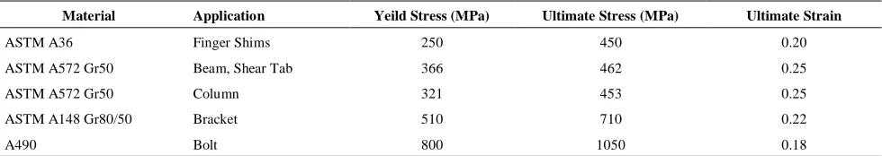
Therefore, to consider the frictional forces, Coulomb’s coefficient is assumed to be 0.33, which yields the best results. The mechanical properties of all component materials are taken from the experimental specimens listed in Table 1. Stress-strain relation for beams, is represented using three-linear constitutive model and materials of other connection components were modeled as bilinear. Stress-strain curves of materials are shown in Appendix 1.
An isotropic multi-linear kinematic hardening rule with a von Mises yielding criterion is applied to simulate plastic deformations of the connection components.
Popov et al. [19] used isotropic multi-linear kinematic hardening for their investigation of cyclic behavior of the T-stub moment bolted connections.
Also, Yang et al. [21] used isotropic multi-linear kinematic hardening for evaluation of Three-dimensional finite element double angle connections under tension and shear. This is suitable for simulation of metal plasticity under cyclic loading [17].
(a)
(b)
Figure 2. Numerical models, (a) Numerical model of reference model 1, (b) Numerical model of reference model 2.
A displacement is then imposed at the beam tip to generate a bending moment at the connection similar to cyclic loadings on the experimental specimens. From Figure 3, it can be seen that similar to experimental specimen, in the FE model, the plastic hinge in the specimen HH-8 connection formed on the beam at 46 cm from the column face. Figures 4 and 5 show the comparison between hysteresis loops of moment at column face versus total rotation (M–θ) and also load versus displacement (F–Δ) of the FE models of the W-series and B-W-series connections and of the test data for KBB connections. It can be seen from Figures 3-5 that a generally good agreement is achieved between the finite element analysis results and the experimental ones for all specimens; so that the maximum amount of error in all specimens is less than 5% which indicates the
feasibility of modeling. In this paper, for all the specimens examined, all of the mechanical properties, geometric characteristics, mesh elements and loading are taken similar to experimental specimens mentioned above. The boundary conditions of the specimens will be described in the section 4.
4. BOUNDARY CONDITIONS AND LOADING
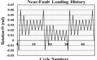
In all specimens, boundary conditions and positions of lateral bracing, are shown in Figure 6. All specimens were subjected to the loading history specified in ATC 24, FEMA 355D and SAC [22-24]. Incremental cyclic loading history was applied up to a 5.6% story drift angle in accordance with ATC 24 [22]. Near-fault loading history was applied based on FEMA 355D and SAC [23, 24]. Near-fault ground motions present a special problem. The response to them is often characterized by one very large excursion, followed by a large number of small cycles with large mean deformation amplitude. It is expected that the cumulative damage is controlled by the first large excursion, which corresponds to monotonic loading of the test specimen. However, the subsequent smaller cycles may lead to additional deterioration that needs to be evaluated. No specific attention has been paid to the characteristics of near-fault response in the development of the basic loading history. The results to be obtained from the SAC near-fault response studies will be utilized to develop such a history. The behavior under such deformation histories cannot be deduced from the basic (standard) loading history and requires a special testing program [24]. To achieve the specified drifts, vertical displacements were imposed at the rigid plate of the beam free end in accordance with Figures 7 and 8, similar to that of the test specimens. The transfer of pre-tensioned force to bolts is defined in two steps. In the first step, pre-tensioned force of the bolts is applied (specifications and pre-tensioned force amount of the bolts were obtained from RCSC [25]) and in the second step, in addition to the continuity of pre-tensioned force of the bolts, loading is done as the applied displacement to end of beams.
TABLE 1. Material properties used in all specimens and specimens to validate numerical and experimental results.
Ultimate Strain Ultimate Stress (MPa)
Yeild Stress (MPa) Application
Material
0.20 450
250 Finger Shims
ASTM A36
0.25 462
366 Beam, Shear Tab
ASTM A572 Gr50
0.25 453
321 Column
ASTM A572 Gr50
0.22 710
510 Bracket
ASTM A148 Gr80/50
0.18 1050
800 Bolt
(a) (b)
Figure 3. View of the experimental and numerical specimens, (a) "Specimen HH-8" [1] after the test, (b) Von mises stress & deformation at final stage of loadings of the "Specimen HH-8" FE model.
(a) (b)
Figure 4. Hysteretic curves for W-series connections (reference model 1), (a) Hysteretic curves for experimental results "Specimen HH-8" [1], (b) Hysteretic curves for numerical model "Specimen HH-8".
(a) (b)
Figure 5. Hysteretic curves for B-Series connections (reference model 2), (a) Hysteretic curves for experimental results "Specimen HH-6" [1], (b) Hysteretic curves for numerical results " Specimen HH-6".
Figure 6. Boundary condition & position of beam lateral bracing in numerical study.
Figure 8. Near-Fault loading history used in numerical models.
5. NUMERICAL RESULTS
Two reference models were created in order to evaluate KBB connections; one model for evaluation of the KBB W-series connection (reference model 1 is the subset of group 1) and another for evaluation of the KBB B-series connection (reference model 2 is the subset of group 2). Reference models are models that have been used for verification. Each group has 10 sub-models. Some specifications such as the pre-tensioned force in column bolts and the friction coefficient have been changed in each group. The beam used in models is I-shaped. The bracket proportions were obtained from AISC 358. Details and proportions of the brackets and shims are depicted in Appendix 2,3. Specifications and pre-tensioned force amount of the bolts were obtained from RCSC Specifications [25]. Other specifications of the specimens have been shown in Table 2. In the experiments performed by ICF Kaiser engineering group, some specimens whose brackets were mainly W2.1 and B2.1 had pinches in hysteresis curves. In addition, their energy dissipation capability was lower than those of other models. Therefore, W2.1 and B2.1 brackets were used to identify the effective factors in reducing the performance and decreasing the energy dissipation of these connections. In order to consider the most critical status, maximum beam depth applicable for these brackets was used. The panel zone of these connections was the strong type. The ratio of the column to the beam was compatible with AISC360
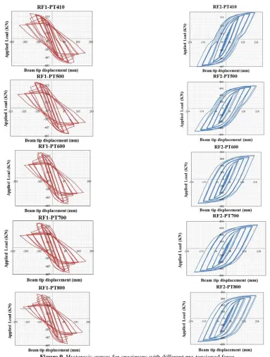
criteria [26]. Also, with regards to AISC 358, the column did not require a continuity plate. The specifications of all specimens are listed in Table 3. Figure 9 clearly shows that the pinch in hysteresis curves reduces by increasing pre-tensioned forces. Although bolt tensile strength relations of AISC 358 have been met according to Equation (1) [15], the pre-tensioned force of the bolts of the upper row of the bracket was decreased due to the high rigidity of the brackets and the prying force created by them. Figure 10 shows this pre-tensioned decrease well.
(1-a)
(1-b)
Where:
Mf : Probable maximum moment at the face of the
column, N-mm.
Ab: Bolt nominal cross-sectional area, mm2.
Fnt : Nominal tensile strength of bolt from the AISC
specification, MPa.
deff : Effective beam depth, calculated as the centroidal
distance between bolt groups in the upper and lower brackets, mm.
ncb : Number of column bolts.
Φn: Resistance factor for nonductile limit states.
As shown in Figure 11, the increase in pre-tensioned force of the bolts causes an increase in the energy dissipation of the specimen. Also, it is clear that the energy dissipation in group 2 connections is more than group 1 connections.
Figure 9. Hysteresis curves for specimens with different pre-tensioned force
(b)
Figure 10. Moment-Strain curve, (a) moment-strain curve for reference model 1, (b) moment-strain curve for reference model 2.
(a) (b)
Figure 11. Cumulative energy dissipation curves, (a) Total energy dissipation for group models 1, (b) Total energy dissipation for group models 2.
TABLE 3. Summary of numerical specimens specifications.
Maximum of cumulative energy dissipation (kJ) Coefficient of friction
Pre-stressed force (kN) Specimens Group 914 0.33 300 RF1-PT300 Gr o up 1 1176 0.33 410 RF1-PT410 1240 0.33 500 RF1-PT500 1279 0.33 600 RF1-PT600 1307 0.33 700 RF1-PT700 1385 0.33 800 RF1-PT800 1380 0.33 500 RF1-N.Shims 1376 0.33 500 RF1-U.Shims 1185 0.25 450 RF1-Fric0.25 1224 0.40 450 RF1-Fric0.40 1202 0.33 300 RF2-PT300 Gr o up 2 1620 0.33 410 RF2-PT410 1711 0.33 500 RF2-PT500 2002 0.33 600 RF2-PT600 2065 0.33 700 RF2-PT700 2088 0.33 800 RF2-PT800 1841 0.33 500 RF2-N.Shims 1839 0.33 500 RF2-U.Shims 1650 0.33 450 RF2-Fric0.30 1641 0.45 450 RF2-Fric0.45
RF1,2-N.Shims: Reference model 1,2 - Shims with uniform thickness.
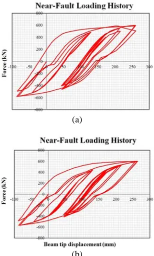
In loadings of this type, the near-fault performance would be acceptable only if the following conditions are met: (1) cumulative damage is controlled in both the loading half cycles, and (2) the connection would not undergo any substantial strength deterioration in its cyclic behavior. Therefore, application of at least two loading half cycles would be required [27]. Upon desirable performance of the connection, either or both the loading half cycles may be continued until failure occurs [27]. In this study, upon completion of the two required loading half cycles, the first half has been repeated. Therefore, in accordance with the mentioned acceptance criteria, the above connections have a suitable performance in the near fault vicinity during both loading half cycles, thus meeting the acceptance criteria. It could obviously be observed that of the two studied connection types, group 2 exhibits a better near fault performance than group 1 since during the third part of loading; the W-series KBB connection sustains a small resistance drop in its hysteresis curve. Therefore, the Kaiser moment connection (particularly the B-series connection) could be considered as a suitable connection for near fault zone. (see Figure 12)
According to the von Mises and the Equivalent Plastic Strain (PEEQ) criteria, performance of all the specimens is acceptable and the plastic hinges are all formed after the brackets. The results also indicate that use of tapered wedge shims would reduce the seismic performance of the connection (in some prototypes, tapered wedge shims had been used). Use of tapered wedge shims would create a double force in the bolts, thus reducing the pre-tensioned force in the bolts. This reduction in tensioned is greater in bolts with pre-tensioned forces less than the minimum allowable RCSC limit.
Using finger shims with constant thickness, or not using shims at all would solve this problem. Also, increasing the pre-tensioned force to the maximum allowable limit would decrease the mentioned drop in bolts pre-tensioned force. Because of the reduction of pre-tensioned force would cause also, reduction of energy dissipation and create a pinch in the hysteresis curve of the specimens. Figure 13 shows the hysteresis curves obtained for these specimens in different cases.
In this study, as the steel surface was unpainted and cleaned through abrasion, it would be classified as a class A surface.
To evaluate the effect of the coefficient of friction on energy dissipation as well as hysteresis curves, this coefficient was taken to fall outside the range determined in the AISC code for class A steel surfaces, varying between 0.25 and 0.40 for group 1, and between 0.30 and 0.45 for group 2. Upon increasing the coefficient of friction, the energy dissipation in group 1 connections remained almost constant, while in the KBB connection in group 2, it increased. This increase could be due to the increase of plastic deformation at
hinge location as a result of reduction of slippage in beam flange brackets. Figure 14 shows the difference in energy dissipation for both groups, and Figure 15 shows the effect of the friction coefficient on hysteresis curves.
(a)
(b)
Figure 12. Near-Fault hysteresis curves of the reference models, (a) Reference model 1, (b) Reference model 2.
(a)
(c)
(d)
Figure 13. Hysteresis curves of specimens, (a) hysteresis curves of reference model 1 without Finger shims, (b) hysteresis curves of reference model 1 with uniform Finger shims, (c) hysteresis curves of reference model 2 without Finger shims, (d) hysteresis curves of reference model 2 with uniform Finger shims.
(a)
(b)
Figure 14. Cumulative energy dissipation curves, (a) RF1-Fric0.25 & RF1-Fric0.40 models, (b) RF2-Fric0.30 & RF1-Fric0.45 models.
(a)
(b)
(c)
(d)
Figure 15. Hysteretic curves for specimens with different coefficient of frictions, (a) Fric0.25 model, (b) RF1-Fric0.40 model, (c) RF2-Fric0.30 model, (d) RF2-Fric0.45 model.
yielding of the beams and was primarily due to the strain hardening of the beams. There was no visible sign of distress to the web plate of the bracket and the yielding did not appear to affect performance of the connection. This study also shows that, at some parts of the bracket, the design of the connection is conservative. These brackets are made of A148 cast steel, so this connection has a high resistance, and is more rigid (as compared with similar connections, particularly deep beams) due to greater stiffness of its brackets. In W2.1 and B2.1 brackets, the pre-tensioned force reduction in deep beams and beams with relatively high flange thickness increased due to the high prying force resulting from high brackets rigidity. For brackets of this type, it would be better either to increase the number of bolts connecting the bracket to the column in deep beams or beams with large flange thicknesses (greater than 22 mm), or to limit to smaller sizes (in the related codes) the beam sections used for such brackets. Also, due to excessive reduction of pre-tensioned force, tapered wedge shims are not recommended and finger shims with constant thickness are preferred. Roughening the beam flange in B-Series brackets would increase the energy dissipation of this type of connection. Ultimately, this connection exhibits acceptable seismic performances under both normal (standard) and near fault loading histories and can be used as a suitable connection for special moment frames.
(a)
(b)
Figure 16. Maximum stress in brackets,(a) Reference model 1, (b) Reference model 2.
6. CONCLUSIONS
In this study, the seismic behavior of moment connection, KBB, was examined under standard and near-fault loading histories, that contains the following results:
v The seismic performance of the KBB connection is reliable in the near-fault zone. Hence, it can be used as a proper connection for special moment resisting frame in the near-fault zone.
v Due to high depth of beam section in deep beams and rigidity of the brackets, the pre-tensioned force reduced in top row bolts of bracket.
v Use of the tapered wedge shims, intensifies pinching effect in hysteresis curves and reduce pre-tensioned force in the column bolts.
v Seismic performance and energy dissipation of the B-series connection is better than W-series.
v By increasing the pre-tensioned force in bolts (up to maximum allowable amount of RCSC), the pinch effect in the hysteresis curves is reduced and total energy dissipation is increased.
v By increasing friction coefficient in the B-series of the KBB connection, total energy dissipation is increased. Also, friction coefficient in W-series of the KBB connection has no effect on energy dissipation.
7.
REFERENCES1. Tremblay, R., Filiatrault, A., Timler, P. and Bruneau, M., "Performance of steel structures during the 1994 Northridge earthquake", Canadian Journal of Civil Engineering, Vol. 22, No. 2, (1995), 338-360.
2. Youssef, N. F. G., Bonowitz, D. and Gross, J. L., "A survey of steel moment-resisting frame buildings affected by the 1994 Northridge earthquake, US National Institute of Standards and Technology, (1995).
3. Venture, S. A. C. J., "Recommended seismic design criteria for new steel moment-frame buildings, Federal Emergency Management Agency, (2000).
4. Tsai, K. C. and Popov, E. P., "Cyclic behavior of end-plate moment connections", Journal of Structural Engineering, Vol. 116, No. 11, (1990), 2917-2930.
5. Seradj, H., "Ductile End-Plate Connections Utilizing Plate Yielding, University of Oklahoma. Norman. Oklahoma, MS thesis. School of Civil Engineering and Environmental Science. , (1997).
6. Adey, B., Grondin, G. and Cheng, J. J. R., "Cyclic loading of end plate moment connections", Canadian Journal of Civil Engineering, Vol. 27, No. 4, (2000), 683-701.
7. Shi, G., Shi, Y., Wang, Y. and Bradford, M. A., "Numerical simulation of steel pretensioned bolted end-plate connections of different types and details", Engineering Structures, Vol. 30, No. 10, (2008), 2677-2686.
8. Chen, Y. and Wang, S., "Research on end-plate connection with non-completely penetrated welds", Journal of Constructional Steel Research, Vol. 65, No. 1, (2009), 228-236.
9. Azizinamini, A., Monotonic response of semi-rigid steel beam to column connections, in 1982, University of South Carolina:
Columbia:.
10. Shen, J. and Astaneh-Asl, A., "Hysteretic behavior of bolted-angle connections", Journal of Constructional Steel Research, Vol. 51, No. 3, (1999), 201-218.
11. Kishi, N., Ahmed, A., Yabuki, N. and Chen, W., "Nonlinear finite element analysis of top-and seat-angle with double web-angle connections", Structural Engineering and Mechanics, Vol. 12, No. 2, (2001), 201-214.
12. Kasai, K., Hodgson, I. and Bleiman, D., "Rigid-bolted repair method for damaged moment connections", Engineering Structures, Vol. 20, No. 4, (1998), 521-532.
13. Adan, S. M. and Gibb, W., "Experimental Evaluation of Kaiser Bolted Bracket Steel Moment-Resisting Connections",
Engineering journal, Vol. 46, No. 3, (2009), 181-196.
14. Uang, Ch.-M., Kim, D.-W., Sim, H.-B., Jolla, L. and Adan, S., M., "Cyclic Testing and Analysis of Retrofitted Pre-Northridge Steel Moment Connections Using Bolted Brackets", Journal of SEAOC proceedings, (2010).
15. "ANSI/AISC 358-10S11, "Prequalified Connections for Special and Intermediate Steel Moment Frames for Seismic Applications, Chicago, ANSI/AISC, (2011).
16. Adan, S. M. and W. Gibb, "Test Report 98-05-Specimen HH-8",
ICF Kaiser Engineers, (1998).
17. Hibbit, "ABAQUS version 6.10-1 user's manual, Michigan, Carlson & Sorensen Inc, (2010).
18. AISC, Manual of steel construction-load and resistance factor design., American Institute of Steel Construction, Chicago, IL. (1995)
19. Takhirov, S. and Popov, E. P., "Bolted large seismic steel beam-to-column connections Part 2: numerical nonlinear analysis",
Engineering Structures, Vol. 24, No. 12, (2002), 1535-1545.
20. Gerami, M., Saberi, H., Saberi, V. and Saedi Daryan, A., "Cyclic behavior of bolted connections with different arrangement of bolts", Journal of Constructional Steel Research, Vol. 67, No. 4, (2011), 690-705.
21. Yang, J. G., Murray, T. and Plaut, R., "Three-dimensional finite element analysis of double angle connections under tension and shear", Journal of Constructional Steel Research, Vol. 54, No. 2, (2000), 227-244.
22. , ATC-24, Guidelines for Cyclic Seismic Testing of Components of Steel Structures., Applied Technology Council, Redwood City, CA. (1992).
23. Roeder, C. W. and Venture, S. A. C. J., "State of the Art Report on Connection performance, SAC Joint Venture, (2000). 24. SAC/BD-97/02 Version 1.1, "Protocol for fabrication,
inspection, testing, and documentation of beam-column connection tests and other experimental specimens", Rep. No. SAC/BD-97, Vol. 2, (1997-2002).
25. RCSC, "Specification for Structural Joints Using High-Strength Bolts, Research Council on Structural Connections, (2009). 26. "ANSI/AISC 360-05, Specification for Structural Steel
Buildings, Chicago, American Institute of Steel Construction, (2005).
27. H. Krawinkler, A. Gupta, R. Medina, N. Luco., Development of Loading Histories for Testing of Steel Beam-to-Column Assemblies, in Department of Civil & Env Engineering., Stanford University, (2000)
APPENDIX
Appendix 1:
Stress-strain curves of the materials, which used in specimens, are shown in Figure 17.
Appendix 2:
Kaiser bolted bracket detailing, are shown in Figure 18 and Table 4, 5.
(a)
(b)
Figure 18. KBB connection detailing, (a) W-series connection detailing, (b) B-series connection detailing [15].
TABLE 4. Kaiser bolted bracket proportions [15].
TABLE 5. Bracket design proportions [15].
Appendix 3:
Tapered wedge shims detailing, is shown in Figure 19.
Figure 19. Tapered wedge shims detailing.
Influential Factor in Improving the Seismic Performance of the Kaiser Bolted Bracket
Moment Connection
F. Shahidi a, F. Nateghi-A b, M. S. Razzaghi c, F. Shahidi d
a Department of Civil Engineering and Surveying, Qazvin Branch, Islamic Azad University, Iran b International Institute of Earthquake Engineering and Seismology of Tehran, Iran
c Faculty of Civil Engineering and Surveying, Qazvin Branch, Islamic Azad University, Iran d Department of Civil Engineering, Islamic Azad University of Takestan, Iran
P A P E R I N F O
Paper history: Received 26 August 2012
Accepted in revised form 18 October 2012
Keywords:
Standard Loading History Near-fault Loading History
Kaiser Bolted Bracket Connection (KBB) Pinch
هﺪﯿﮑﭼ
ﻪﻟﺰﻟززاﺲﭘ
1994
ﻪﻈﺣﻼﻣﻞﺑﺎﻗداﺪﻌﺗ،ﺎﯿﻧﺮﻔﯿﻟﺎﮐﺞﯾﺮﺛرﻮﻧ
نﺎﻤﺘﺧﺎﺳزايا
ﺪﻧﺪﯾدترﺎﺴﺧﯽﺸﻤﺧتﻻﺎﺼﺗاﺎﺑيدﻻﻮﻓيﺎﻫ
.
هزﺮﻟدﺮﮑﻠﻤﻋدﻮﺒﻬﺑياﺮﺑيدﺎﯾزتﺎﻘﯿﻘﺤﺗﻪﻌﻗاوﻦﯾازاﺪﻌﺑ
ﺖﻓﺮﮔترﻮﺻﯽﺸﻤﺧتﻻﺎﺼﺗايا
.
ﭻﯿﭘﺖﮐاﺮﺑﯽﺸﻤﺧلﺎﺼﺗا
رﺰﯾﺎﮐهﺪﺷ
ﻪﻣﺎﻧﻦﯿﯾآردهﮋﯾوﯽﺸﻤﺧبﺎﻗياﺮﺑحﺮﻄﻣتﻻﺎﺼﺗازاﯽﮑﯾ،
AISC-358
رﺎﺼﺘﺧارﻮﻃﻪﺑﻪﮐ،ﺖﺳا
KBB
دﻮﺷﯽﻣهﺪﻧاﻮﺧ
.
ﯽﻣﺪﯿﻟﻮﺗﯽﮕﺘﺨﯾرترﻮﺻﻪﺑلﺎﺼﺗاﻦﯾا
دﻮﺷ
.
ﯽﺸﻤﺧلﺎﺼﺗارﺎﺘﻓرﻖﯿﻘﺤﺗﻦﯾارد
KBB
يراﺬﮔرﺎﺑﺖﺤﺗ
ﻪﺧﺮﭼيﺎﻫ
ﻪﻣﺎﻧﻦﯿﯾآردهﺪﺷحﺮﻄﻣﻞﺴﮔﮏﯾدﺰﻧودراﺪﻧﺎﺘﺳايا
يﺎﻫ ATC و FEMA
ﺖﺳاﻪﺘﻓﺮﮔراﺮﻗﯽﺳرﺮﺑدرﻮﻣ
.
ﯽﻣنﺎﺸﻧﺞﯾﺎﺘﻧ ﺪﻫد
ﻪﮐ هزﺮﻟدﺮﮑﻠﻤﻋﺮﺑهوﻼﻋلﺎﺼﺗاﻦﯾا ﺮﯿﺗرد،ﺐﺳﺎﻨﻣيا
ﺖﮐاﺮﺑيﻻﺎﺑﯽﺘﺨﺳﺖﻠﻋﻪﺑ،ﺪﻨﻠﺑعﺎﻔﺗراﺎﺑﯽﯾﺎﻫ
ﺖﮐاﺮﺑيﻻﺎﺑﻒﯾدريﺎﻫﭻﯿﭘرديدﺎﯾزﯽﻣﺮﻫايوﺮﯿﻧ،نآدﺎﯾزعﺎﻔﺗراو
ﯽﻣﺪﯿﻟﻮﺗ ﺪﻨﮐ
.
زاهدﺎﻔﺘﺳاﻦﯿﻨﭽﻤﻫو عﻮﺿﻮﻣﻦﯾا
ﺐﯿﺷ ﯽﺘﺸﮕﻧا ﺮﺷاو
ﺶﯿﭘ يوﺮﯿﻧ ﺶﻫﺎﮐ ﺐﺒﺳ راد
ﭻﯿﭘ ﯽﮔﺪﯿﻨﺗ
ﺖﮐاﺮﺑ يﻻﺎﺑ ﻒﯾدر يﺎﻫ
دﺎﺠﯾا و ﺎﻫ
Pinch
رادﻮﻤﻧ رد
ﺖﺳاهﺪﺷنآﺲﯾزﺮﺘﺴﯿﻫ
.
![Figure 1. Typical Kaiser Bolted bracket moment-resisting connection [1].](https://thumb-us.123doks.com/thumbv2/123dok_us/236868.2018350/2.595.320.521.513.719/figure-typical-kaiser-bolted-bracket-moment-resisting-connection.webp)
![Figure 5. Hysteretic curves for B-Series connections (reference model 2), (a) Hysteretic curves for experimental results "Specimen HH-6" [1], (b) Hysteretic curves for numerical results " Specimen HH-6"](https://thumb-us.123doks.com/thumbv2/123dok_us/236868.2018350/5.595.90.509.433.561/hysteretic-connections-reference-hysteretic-experimental-hysteretic-numerical-specimen.webp)