International Journal of Engineering
J o u r n a l H o m e p a g e : w w w . i j e . i rModeling of Capacitance and Sensitivity of a MEMS Pressure Sensor with
Clamped
Square Diaphragm
B. A. Ganji*, M. Shams Nateri
Department of Electrical & Computer Engineering, Babol University of Technology, Babol, Iran
P A P E R I N F O
Paper history:
Received 06 December 2012
Recivede in revised form 03 February 2013 Accepted 28 February 2013
Keywords:
MEMS Modeling Displacement Capacitance Sensitivity
A B S T R A C T
In this paper, for the first time, the modeling of capacitance and sensitivityfor MEMS capacitive pressure sensor with clamped square diaphragm is presented. In capacitive sensor the sensitivity is proportional to deflection and capacitance changes with pressure. Therefore, first the diaphragm displacement, capacitance and sensitivity of sensor with square diaphragm have been modeled and then simulated using finite element method (FEM). It can be seen that the analytical results agree with simulation. The results also show that the high sensitivity can be achieved by decreasing the diaphragm thickness and increasing its size.
doi:10.5829/idosi.ije.2013.26.11b.08
1. INTRODUCTION1
The MEMS pressure sensor is one of the best developed devices in use today. The pressure sensors are critical for advanced industrial, automotive, petrochemical, aerospace, defense, marine and water industries, meteorology, control systems and process control. Most pressure sensors rely on the piezoresistive sensing principle. However, in the past years capacitive pressure sensors have received increasing attention due to several advantages when compared to the piezoresistive sensors. The main disadvantage of the piezoresistive principle is the inherent temperature dependence of the piezoresistive coefficients. The capacitive micro machined pressure sensors have good stability, higher pressure sensitivity, and lower power consumption compared to the piezoresistive structures [1-4].
Generally, Micro-electromechanical system (MEMS) capacitive pressure sensor consists of a thin, flexible conductive membrane (diaphragm) as one of the electrodes that is separated from a fixed back plate by a small air gap. In capacitive sensors, a thin diaphragm is used as a pressure sensing element [3, 5]. When the diaphragm is exposed to an external uniform pressure the diaphragm deflects causing a decrease in the air gap that results an increase in capacitance
*Corresponding Author Email:[email protected] (B. A. Ganji)
between the diaphragm and the fixed back plate. So,
deflection of the movable part due to applied pressure is sensed and translated into an electrical capacitance change [2].
The sensitivity of the capacitive sensors largely depends on the capacitance change. Hence, modeling of capacitance for exact calculation of the capacitance between the deformed diaphragm and the back plate is necessary. Understanding of capacitance changes in the structure requires more knowledge about mechanical deflection of an upper electrode [6, 7].
In this paper the diaphragm displacement, capacitance and sensitivity of MEMS pressure sensor with clamped square diaphragm have been modeled. To evaluate analytical results, finite element analysis (FEA) is used and compared with the analytical results.
2. CAPACITIVE SENSOR STRUCTURE
to the capacitive changes. Thus, more changes cause the higher sensitivity. As mentioned earlier, the diaphragm displacement should be enhanced so that the changes of capacitor increase.
3. MODELING OF CAPACITANCE AND SENSITIVITY
In this paper, for the first time, the modeling of capacitance and sensitivity for MEMS capacitive pressure sensor with clamped square diaphragm is presented. In our previous works in references [5-8], two new capacitive sensors (fingerprint and microphone) with square diaphragms are presented without modeling of capacitance and sensitivity. But in this work, the new equations have been extracted for calculating the capacitance and sensitivity of the capacitive pressure sensors with square diaphragm and compared with simulation results.
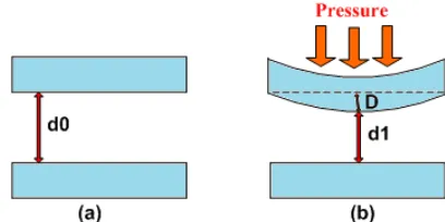
As shown in Figure 2a, the capacitance between two parallel electrodes without external pressure is given by:
0 0 0 A C d e = (1)
where ε0 is permittivity, A is surface of the plate, and d0 is distance between two plates.
From the Figure 2b, after applied pressure, Equation (1) cannot be used for calculating the capacitance of pressure sensor with clamped diaphragm.
Figure 1. Diaphragm displacement due to applied pressure
Figure 2. Electrodes of sensor, (a) without applied pressure, (b) with applied pressure
The shape of the diaphragm can be circular or square. These shapes behave similarly to an applied pressure. For clamped circular diaphragm with small deflection (less than 30% of its thickness) the displacement is given by [9]:
2 2 2
( )
( ) 64
p R r
w r
D
-= (2)
where w, r, R, and P are the deflection, radial distance from the center of the diaphragm, diaphragm radius and applied pressure respectively. Dis the flexural rigidity, given by: 3 2 12(1 ) Eh D v =
- (3 )
where E, h,and ν are the Young's modulus, thickness, and Poisson's ratio of diaphragm, respectively. The central deflection, w, of a flat and circular diaphragm with clamped edges and homogeneous pressure, P, can be calculated from Equation (2) with r = 0:
3 4
4 2 4 2 4
64 64
5.33
12(1 ) (1 )
D W Eh W Eh W
p
R n R n R h
´ ´ æ ö
= = = ´ ç ÷
- - è ø (4)
where E, ν, R, and h are the Yong’s modulus, the Poison’s ratio, the radius and the thickness of the diaphragm, respectively. The mechanical sensitivity of diaphragm is defined as:
dP dw
Sm= (5)
The mechanical sensitivity for circular diaphragm is obtained as:
2
2 2 2
[5.33 / (1 )]
m
w R
S
P ph Eh pR v
= =
- (6)
The central deflection of a flat, clamped square diaphragm is given approximately by [8].
3 4 2 4 4 2 4 ) ( ˆ ) 1 ( 58 . 1 ) ( ˆ ) 1 ( 2 . 4 h w a h E h w a h E P n
n +
-=
(7)
For small deflection, the mechanical sensitivity of a flat square diaphragm can be expressed as:
2
2 2 2
ˆ ˆ
[4.2 / (1 )]
m
w a
S
P ph Eh pa v
= =
¶ - (8)
The capacitance of pressure sensor with circular diaphragm is given by [9]:
1
( )
( , ) f
C rdrd
d w r
e q
q =
-ò -ò
(9)In circular diaphragm, the displacement of the diaphragm is not affected byangle changes, thus w(r,Ө) in Equation (9) can be replaced with w(r). Using Equation (2) in Equation (9) yields:
2
2 2 2
0 0 ( )
64 a
f
C rdrd
p R r d D p e q =
It can be written as: 2
2 2 2
0 0 1 ( ) 1 64 a f C rdrd
p r R
d Dd p e q = -+
ò ò
(11)With assuming: 2 2
8
r R p
u Dd -= (12) 1 . 4 P du rdr dD = (13) which .4 dD rdr du P = (14) and 2 2 0 0 1 .4 1 R f dD C dud
d p u
p
e q
=
+
ò ò
(15)By solving the Equation (15), the capacitance of sensor can be obtained as:
2 1
8 tanh
8 f
D r p
C
pd Dd
pe - é ù
= ê ú
ë û (16)
By replacing D from Equation (3) in Equation (16) we have:
3 2 2
1
2 3
12 (1 )
8 tanh
12 (1 ) 8
f
Eh r p v
C
pd v Edh
pe - é - ù
= ê ú
- êë úû ( 17)
The capacitance versus applied pressure is generally nonlinear due to the nonlinear deflection of the diaphragm. The sensitivity of the pressure sensor can be defined and calculated as following:
2 6 2 3 12(1 ) 49.6 f c C r S
p Ed h
e n
-= =
¶ (18)
The sensor sensitivity depends on the membrane thickness, h, andelectrodes distance, d, under the same pressure. The theory being valid for circular membranes is converted to the square diaphragms assuming equal areas ((2aˆ)2 = pR2) [8]. Thus, the deflection of a flat square diaphragm can be approximated by replacing R2 with 4â2/π in the above mentioned relation for a
moving square diaphragm sensor, the capacitance and sensitivity can be obtained:
2
1
2
8 ta n h
8
f
a
D p
C
p d D d
p
p e
-éæ ö ù
êç ÷ ú
è ø
ê ú
= ê ú
ê ú ê ú ë û (19) 6 2 2 3 2 12(1 ) 49.6 f c a C S
p Ed h
e n
p
æ ö
- ç ÷
¶ è ø
= =
(20)
4. RESULTS AND DISCUSSION
First, we examine the appropriate shape for the diaphragm of the pressure sensor. The capacitive structure with various shapes such as circular or square can be designed. A simulation using FEA (Finite Element Analysis) method has been done for square shape with dimensions of 50 micrometer and circular diaphragm with a diameter of 50 micrometer. The diaphragm is made of is 2 micrometer thick aluminium foil (see Figure 3).
Figure 4 shows the simulation results. It can be seen that the square diaphragm has more deflection than the circular one under the same load. From Figure 4, the mechanical sensitivity (dW/dP) of the square diaphragm is 1.186×10⁻¹³ and the circular one is 0.96×10⁻¹³. Since
the mechanical sensitivity of the square diaphragm is more than that of the circular one, thus, the circular diaphragm has been chosen for sensor structure.
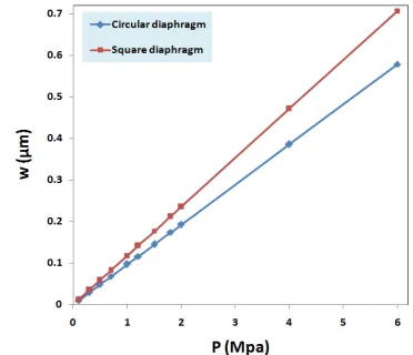
Figures 5 and 6 show the analytical and simulation results of displacement versus pressure for square and circular diaphragms, respectively. Figure 7 shows the simulated and calculated capacitance of sensor versus pressure for square diaphragm. From Figure 7, the calculated sensitivity of sensor (dC/dP) is 1.705×10⁻²¹,
while the simulation result is 1.561×10⁻²¹. It can be seen
that the analytical result is very close to the simulation result.
Figure 3. Capacitive sensors with different diaphragms
Figure 5. Displacement of square diaphragm vs. pressure
Figure 6. Displacement of circular diaphragm vs. pressure
Figure 7. Capacitance vs. pressure for square diaphragm
Figure 8 shows the effect of diaphragm size on displacement. It can be seen that, by increasing the size of the diaphragm, the displacement also increases. Figure 9 shows the capacitance of sensor versus diaphragm size. As shown in Figures 9, by increasing the dimensions of the diaphragm, the capacitance has increased.
Figure 8. Displacement of square diaphragm vs. diaphragm size
Figure 9. Capacitance vs. diaphragm size
Figure 10. Mechanical sensitivity of square diaphragm vs. diaphragm size
thickness. As can be seen in Figure 12, the thinner diaphragm causes more displacement. However, by reducing too much the thickness of diaphragm, maybe has been too bended and broken.
Figure 11. Sensor sensitivity vs. diaphragm size
Figure 12. Displacement of square diaphragm vs. diaphragm thickness
Figure 13. Capacitance vs. diaphragm thickness
Figure 14. Mechanical sensitivity of square diaphragm vs. diaphragm thickness
Figure 15. Sensor sensitivity vs. diaphragm thickness
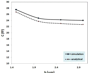
The effect of diaphragm thickness on capacitance is shown in Figure 13. It can be seen that, the high capacitance is related to the thinner diaphragm. The effect of diaphragm thickness on sensitivity are shown in Figures 14 and 15. As shown in Figures 14 and 15, the high sensitivity is related to the thinner diaphragm (0.5 μm). Thus, to have a high sensitivity, the diaphragm size should be increased and thickness decreased. It can be seen that the analytical results is very close to the simulation results.
5. CONCLUSION
MEMS simulation tool (Intellisuite) using finite element method. The results show that the theoretical results in good agreement with the simulation. The results also show that as the diaphragm size increases or its thickness decreases, the diaphragm deflection, and capacitance will be increased under the same load.
6. REFERENCES
1. Pedersen, T., Fragiacomo, G., Hansen, O. and Thomsen, E. V.,
"Highly sensitive micromachined capacitive pressure sensor with reduced hysteresis and low parasitic capacitance", Sensors and Actuators A: Physical, Vol. 154, No. 1, (2009), 35-41. 2. Zhou, M.-X., Huang, Q.-A., Qin, M. and Zhou, W., "A novel
capacitive pressure sensor based on sandwich structures",
Journal of Microelectromechanical Systems, Vol. 14, No. 6, (2005), 1272-1282.
3. Zhang, Y., Howver, R., Gogoi, B. and Yazdi, N., "A high-sensitive ultra-thin mems capacitive pressure sensor", in Solid-State Sensors, Actuators and Microsystems Conference (TRANSDUCERS), 16th International, IEEE. (2011), 112-115.
4. Rahman, M. M. and Chowdhury, S., "Square diaphragm cmut
capacitance calculation using a new deflection shape function",
Journal of Sensors, Vol. 2011, (2011).
5. Ganji, B. A. and Majlis, B. Y., "Fabrication and characterization
of a new mems capacitive microphone using perforated diaphragm", International journal of Engineering, Vol. 22, No. 2, (2009), 153-160.
6. Ganji, B. A. and Nateri, M., "Fabrication of a novel mems capacitive microphone using lateral slotted diaphragm",
International Journal of Engineering-Transactions B: Applications, Vol. 23, No. 3&4, (2010), 191.
7. Ganji, B. A. and Nateri, M. S., "A high sensitive mems
capacitive fingerprint sensor using slotted membrane",
Microsystem Technologies, Vol. 19, No. 1, (2013), 121-129. 8. Ganji, B. A. and Majlis, B. Y., "Analytical analysis of flat and
corrugated membranes for mems capacitive sensors",
International Journal of Nonlinear Dynamics Engineering Science, Vol. 1, No. 1, (2008), 47-57.
9. Timoshenko, S., Woinowsky-Krieger, S. and Woinowsky, S.,
"Theory of plates and shells", McGraw-hill New York, Vol. 2, (1959).
Modeling of Capacitance and Sensitivity of a MEMS Pressure Sensor with
Clamped
Square Diaphragm
B. A. Ganji, M. Shams Nateri
Department of Electrical & Computer Engineering, Babol University of Technology, Babol, Iran
P A P E R I N F O
Paper history:
Received 06 December 2012
Recivede in revised form 03 February 2013 Accepted 28 February 2013
Keywords:
MEMS Modeling Displacement Capacitance Sensitivity
هﺪﯿﮑﭼ
لﺪﻣرﺎﺑﻦﯿﻟواياﺮﺑﻪﻟﺎﻘﻣﻦﯾارد
ﺲﺣﺖﯿﺳﺎﺴﺣونزﺎﺧيزﺎﺳ
ﯽﻧزﺎﺧيﺎﻫﺮﮔ
ﺮﻣﻢﮔاﺮﻓﺎﯾدﺎﺑ ﯽﻌﺑ
ﻪﺋاراﺖﺑﺎﺛفﺮﻃرﺎﻬﭼ
ﺖﺳاهﺪﺷ
.
ﺲﺣ ﯽﻣيزاﻮﻣدوﺮﺘﮑﻟاوديارادﯽﻧزﺎﺧﺮﮔ ًﻻﻮﻤﻌﻣﻪﮐﺪﺷﺎﺑ
ﺑﺎﺟﺖﯿﻠﺑﺎﻗدوﺮﺘﮑﻟاﮏﯾ ﻪ
اررﺎﺸﻓلﺎﻤﻋاﺮﺛاﺮﺑﯽﯾﺎﺟ
دراد
.
ﺲﺣﻪﻧﻮﮔﻦﯾا دﺮﮑﻠﻤﻋرد ﯽﻠﺻا ﺮﺘﻣارﺎﭘ ﻪﮐﯽﻧزﺎﺧتاﺮﯿﯿﻐﺗ
ﺎﻫﺮﮔ ﺖﺳ
ﺑﺎﺟسﺎﺳا ﺮﺑ
ﻪ
دﺎﺠﯾادوﺮﺘﮑﻟا ﻦﯿﻤﻫ ﯽﯾﺎﺟ
ﯽﻣ دﻮﺷ
.
رد ﺲﺣ
ﯽﻧزﺎﺧيﺎﻫﺮﮔ
ﺖﯿﺳﺎﺴﺣ ﺐﺳﺎﻨﺘﻣ تاﺮﯿﯿﻐﺗﺎﺑ
ﺐﺴﺣﺮﺑنزﺎﺧ
رﺎﺸﻓ ﺖﺳا و ﺎﺟاﺪﺘﺑاﻦﯾاﺮﺑﺎﻨﺑ ﺑﻪ
ﯽﺋﺎﺟ
ﻢﮔاﺮﻓﺎﯾد ،
ونزﺎﺧﺖﯿﻓﺮﻇ
ﺖﯿﺳﺎﺴﺣ ﺲﺣ ﺮﮔ لﺪﻣ يزﺎﺳ ،
هﺪﺷيزﺎﺳﻪﯿﺒﺷدوﺪﺤﻣءاﺰﺟاشورزاهدﺎﻔﺘﺳاﺎﺑﺲﭙﺳو
ﻪﮐﺪﻧا
ﺞﯾﺎﺘﻧ نﺎﺷ رﺎﯿﺴﺑ ﮏﯾدﺰﻧ ﻢﻫﻪﺑ ﺪﻨﺘﺴﻫ
.
ﯽﻣنﺎﺸﻧﻦﯿﻨﭽﻤﻫﺞﯾﺎﺘﻧ
هزاﺪﻧاﺶﯾاﺰﻓاوﻢﮔاﺮﻓﺎﯾدﺖﻣﺎﺨﺿﺶﻫﺎﮐﺎﺑﻪﮐﺪﻨﻫد
ي نآ ،
ﺲﺣﺖﯿﺳﺎﺴﺣ
ﯽﻣﺶﯾاﺰﻓاﺮﮔ
ﺪﺑﺎﯾ
.