NEW STILLING BASINS DESIGNS FOR
DEEP RECTANGULAR OUTLETS
D. V. S. Verma, Arun Goel and Vipun Rai
Department of Civil Engineering, National Institute of Technology Kurukshetra, 136119, Haryana, India
[email protected] - [email protected]
(Received: June 8, 2003 – Accepted in Revised form: December 25, 2003)
Abstract The experimental study reported here is intended to evolve new designs of stilling basins
for deep and narrow openings used as outlets. Several appurtenances such as grid, Impact wall, stepped wall, weir wall, sloping end sill and wedge shaped blocks are used to study their influence on the hydraulic performance of the stilling basins with an aim to propose efficient stilling basin models. All the models were tested at inflow Froude number Fr = 4.89 keeping a constant run time and same erodible bed material for each stilling basin model for comparison of the performance. The performance of each model was evaluated by observing the maximum depth of scour and its location after the end sill. A non-dimensional number named as Scour Index has been evolved for comparing the performance of the different stilling basin models. The use of wedge shaped blocks as a splitter block and baffle blocks reduced the depth of scour indicating a significant dissipation of energy and good flow conditions, downstream of the stilling basin.
Key Words Rectangular Openings, Stilling Basin, Wedge Shaped Blocks
ﻩﺪﻴﻜﭼ
ﻩﺪﻴﻜﭼ
ﻩﺪﻴﻜﭼ
ﻩﺪﻴﻜﭼ
ﻲﺳﺭﺮﺑ ﻚﻳﺭﺎﺑ ﻭ ﻖﻴﻤﻋ ﻲﺟﻭﺮﺧ ﺎﺑ ﻱﺯﺎﺳ ﻡﺍﺭﺁ ﻪﭽﺿﻮﺣ ﻱﺍﺮﺑ ﺪﻳﺪﺟ ﺡﺮﻃ ﺪﻨﭼ ،ﻲﺑﺮﺠﺗ ﻖﻴﻘﺤﺗ ﻦﻳﺍ ﺭﺩ ﺖﺳﺍ ﻩﺪﺷ .
،ﻱﺍ ﻪﻠﭘ ﻩﺭﺍﻮﻳﺩ ،ﻱﺭﺍﺩﺭﻮﺧﺮﺑ ﻩﺭﺍﻮﻳﺩ ،ﻱﺭﻮﺗ ﻪﻜﺒﺷ ﺪﻨﻧﺎﻣ ﻝﺪﻣ ﺕﺎﻌﻄﻗ ﻪﻧﻮﮔ ﺪﻨﭼ ﻲﻜﻴﻟﻭﺭﺪﻴﻫ ﻲﻳﺍﺭﺎﻛ
ﺶﻣﺍﺭﺁ ﻪﭽﺿﻮﺣ ﺭﺩ ﻞﻜﺷ ﻩﻮﮔ ﺕﺎﻌﻄﻗ ﻭ ﻩﺪﻨﻨﻛ ﻡﺍﺭﺁ ﺭﺍﺩ ﺐﻴﺷ ﻩﺭﺍﻮﻳﺩ ،ﻲﺸﻳﺎﺳ ﻩﺭﺍﻮﻳﺩ ﺖﺳﺍ ﻩﺪﺷ ﻲﺳﺭﺮﺑ
. ﺭﻮﻈﻨﻣ ﻪﺑ
ﻱﺍﺮﺑ ﻱﺩﻭﺭﻭ ﺩﻭﺮﻓ ﺩﺪﻋ ﻭ ﻩﺪﺷ ﻪﺘﻓﺮﮔ ﺶﻳﺎﺳ ﻞﺑﺎﻗ ﺮﺘﺴﺑ ﺲﻨﺟ ﻭ ﺶﻳﺎﻣﺯﺁ ﻥﺎﻣﺯ ،ﻒﻠﺘﺨﻣ ﺕﺎﻌﻄﻗ ﻲﻳﺍﺭﺎﻛ ﻪﺴﻳﺎﻘﻣ ﺎﻬﻧﺁ ﻪﻤﻫ ٨٩ / ٤
ﺖﺳﺍ ﻩﺪﺷ ﺭﻮﻈﻨﻣ .
ﺭﺩ ﻥﺁ ﻪﻠﺻﺎﻓ ﻭ ﻩﺪﺷ ﻪﺘﺴﺷ ﻖﻤﻋ ﻩﺪﻫﺎﺸﻣ ﺎﺑ ،ﻝﺪﻣ ﺕﺎﻌﻄﻗ ﺯﺍ ﻚﻳ ﺮﻫ ﻲﻳﺍﺭﺎﻛ
ﺩﻮﺷ ﻲﻣ ﻦﻴﻴﻌﺗ ﻩﺪﺷ ﻡﺍﺭﺁ ﺖﺳﺩ ﻦﻴﺋﺎﭘ .
ﻌﺑ ﻥﻭﺪﺑ ﺩﺪﻋ ﻚﻳ ﻲﻳﺍﺭﺎﻛ ﻥﺍﻮﺘﺑ ﺎﺗ ﺖﺳﺍ ﻩﺪﺷ ﻒﻳﺮﻌﺗ ﻦﺘﺴﺷ ﺶﻳﺪﻧﺍ ﻡﺎﻨﺑ ﺪ
ﺩﻮﻤﻧ ﻪﺴﻳﺎﻘﻣ ﺮﮕﻳﺪﻜﻳ ﺎﺑ ﺍﺭ ﻒﻠﺘﺨﻣ ﻱﺎﻬﻟﺪﻣ .
،ﺭﺍﺩ ﻪﺒﻟ ﻭ ﻩﺪﻨﻓﺎﻜﺷ ﺕﺎﻌﻄﻗ ﻥﺍﻮﻨﻋ ﻪﺑ ﻞﻜﺷ ﻩﻮﮔ ﺕﺎﻌﻄﻗ ﺩﺮﺑﺭﺎﻛ ﺎﺑ
ﻪﭽﺿﻮﺣ ﺖﺳﺩ ﻦﻴﺋﺎﭘ ﺭﺩ ﻭ ﺩﻮﺷ ﻲﻣ ﻪﺘﺳﺎﻛ ﻱﺮﻴﮕﻤﺸﭼ ﺕﺭﻮﺻ ﻪﺑ ﻱﮊﺮﻧﺍ ﻑﻼﺗﺍ ﺯﺍ ﻭ ﻪﺘﻓﺎﻳ ﺶﻫﺎﻛ ﻦﺘﺴﺷ ﻖﻤﻋ ﻲﺑﻮﺧ ﻥﺎﻳﺮﺟ ﻂﻳﺍﺮﺷ ،ﺶﻣﺍﺭﺁ ﺪﻳﺁ ﻲﻣ ﺖﺳﺪﺑ
.
1. INTRODUCTION
Energy dissipation is a common problem in the design of any hydraulic structure. Stilling basins are used to dissipate the excess kinetic energy of flow to ensure the safety of overflow spillway, chutes, sluices, pipe outlets etc. Some of the recommended stilling basins designs for rectangular openings are USBR impact type VI stilling basin [1], manifold type energy dissipater
in the hydraulic behavior of the rectangular openings and the circular openings. The floor of the basin is depressed and design is suitable for Froude number Fr = 1.5 to 7.0.
In the Manifold type energy dissipater, most of the excess energy is dissipated by the diffusion of the submerged jets. The inflow in the form of high velocity jet is made to rise upwards through the rectangular grid openings by provision of adverse slope to the floor of the entrance of the conduit. The dissipation of energy is achieved by the diffusion of the jets coming out from the manifold into the tail water channel. The recommended arrangement of the stilling basin is not very easy to construct.
When water flows through an outlet, it has very high kinetic energy, which has to be dissipated so that safety of the downstream channel is not endangered. In the case of outlet, the jet of water issues in the form of high velocity concentrated jet, which needs to be spread out into the full width of the basin for significant energy dissipation. This spreading of the jet requires additional length of the basin. Moreover, outlets have to operate continuously and under different flow conditions.
Keeping these salient points and problems in view, attempts are made to evolve new and efficient stilling basin designs for the rectangular openings in the present work by using various configurations of the appurtenances.
2. THEORETICAL CONSIDERATIONS OF STILLING BASIN MODELS
The stilling basins are generally designed on the basis of inflow Froude number Fr and the results of model studies at a given Froude number. The Froude number for the stilling basin are defined as Fr = V/ (gy)½ where V = velocity of incoming flow to the stilling basin or efflux velocity of outlet, g = acceleration due to gravity and y = diameter of circular outlet or pre jump depth. If the shape of the outlet opening is other than circular, than the area of opening is converted into equivalent diameter as mentioned by Bradley and Peterka [1] and Froude number is calculated on the basis of equivalent diameter de in place of y.
3. EXPERIMENTAL SETUP
The experimental model study was carried out in a rectangular fixed bed flume. A masonry tank was constructed on the upstream end of the flume to supply discharge at the required Froude number. A rectangular opening 2.54cm wide and 10.16cm height was made in a tank whose downstream face was flushed with the upstream vertical wall of the flume and smooth entry for the outlet was provided.
At the bed of the channel, a wooded board was provided to facilitate the fixing of the stilling basin appurtenances on it. A 15cm erodible sand bed-having thickness as 15cm of particle size passing 2.36mm I.S. sieve and retained on 1.18mm I.S. sieve was provided for studying the scour at the downstream of the stilling basin. A tailgate was used to control downstream water level in the flume. The duration of running time was kept constant at one hour for each model for the purpose of comparison.
4. EXPERIMENTAL PROCEDURE
5. EXPERIMENTAL SCHEME
The model studies were conducted at inflow Froude number Fr = 4.89. The Froude number is based on the diameter of equivalent circular area of the rectangular outlet. The width and the length of stilling basin models were kept as 6d and 12d respectively where d is the width of the rectangular outlet. Various shapes and sizes of appurtenances [3] like a grid, impact wall, stepped wall, weir wall, a sloping end sill were used in the different configurations of the stilling basin models SBR-1 to SBR-3.
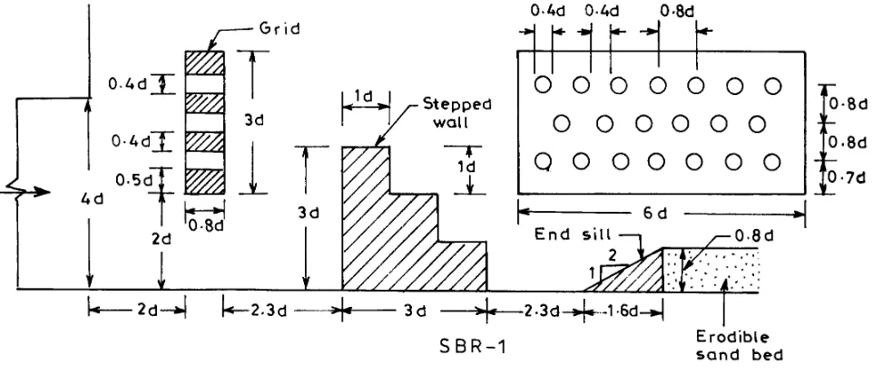
Model SBR-1
A grid of height 3d placed at 2d with a gap at bottom to 2d, a stepped wall of height 3d having each step size 1d X 1d (3 No.) placed at a distance of 5.1d from the exit of the outlet and a sloping end sill of height 0.8d (Figure 1). The diameter of the hole is 0.4d and clear spacing between two consecutive holes is also 0.4d. The three rows of holes are provided in a staggered manner as shown in Figure 1.Model SBR-2
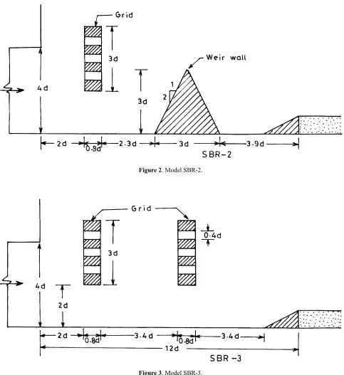
A grid of height 3d placed at 2d with a gap at bottom equal to 2d, a weir wall of height 3d, having side slopes 1H: 2V placed at a distance of 5.1d from the exit of the outlet and a sloping end sill of height 0.8d (Figure 2).Model SBR-3
The first grid is of height 3d placed at 2d with a gap at bottom equal to 2d and second grid of height 3d placed at 6.2d with a gap at bottom equal to 2d and a sloping end sill of height 0.8d (Figure 3).A wedge shaped block of vertex angle 150o and cut back on sides at 90o was adopted for the development of the stilling basin for spillways and barrages with low inflow Froude numbers Fr = 2.5 to 4.5 [4,5]. The wedge shaped block of vertex angle 150o and cut back on sides at 90o was also used as a splitter block for improving the efficiency of the energy dissipaters for circular outlets [6,7]. A strong circulatory movement of water with vertical axis forms on either side of the block in the cutback portion resulting in the increased wake area (Figure 4). The chances of cavitation on such blocks are also minimized, because the downstream portion of the block is shaped such that boundaries are away from the regions where the cavities collapse [8]. In the present study, similar wedge shaped blocks with a vertex angle 150o cut back on sides at 90o are used as a splitter block as well as baffle blocks in the development of new stilling basin models (stilling basin models SBR-4 to SBR-8).
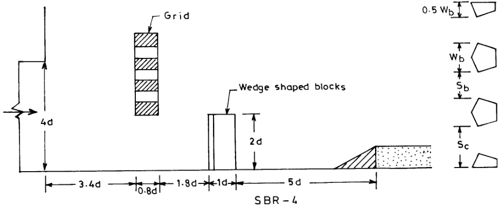
Model SBR-4
A grid of height 3d placed at 2d with a gap at bottom equal to 2d, a row of wedgeshaped baffle blocks placed at a distance of 6d from the outlet and a sloping end sill of height 0.8d. The row of the wedge shaped baffle blocks has two full blocks of size and spacing (wb = 1d, hb= 2d, sb = 1d, sc = 1.5d) and two half blocks
where wb is width and hb is height of the block, sb is spacing between two blocks and sc is spacing between block and side wall (Figure 5).
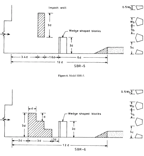
Model SBR-5
An impact wall of height 3d withFigure 2. Model SBR-2.
a bottom gap 2d placed at 3.4d, a row wedge shaped baffle blocks similar to model SBR-4 and a sloping end sill of height 0.8d (Figure 6).
Model SBR-6
A stepped wall of height 3d is placed at 2d from the exit of the outlet and rest of the appurtenances are same with the model SBR-5 (Figure 7)Model SBR-7
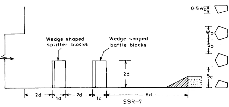
A wedge shaped splitter block of size (wb = 1d and hb= 2d) placed at 1.7d at the center of the opening and a row of wedge shaped baffle blocks at 5.6d (similar to SBR-4) from the exit of the outlet placed at 5d and a sloping end sill of height 0.8d (Figure 8).Model SBR-8
A wedge shaped splitter block ofFigure 4. Increased wake area circulatory movement of water with vertical axis in Model SBR-4.
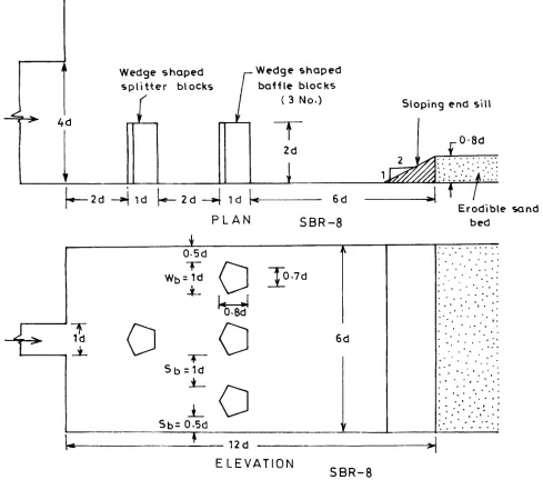
size (wb = 1d and hb = 2d) placed at 2d at the center of the opening and a row of wedge shaped baffle blocks at 5d of size and spacing (wb = 1d, hb = 2d, sb = 1d and sc = 0.5d) and a sloping end sill of height 0.8d (Figure 9).
6. DISCUSSION OF RESULTS
The data of maximum depth of scour and its location after the end sill for each stilling basin model and has been placed in the Table 1 along
Figure 6. Model SBR-5.
with visual observations during the testing of the models. In general, the performance of a stilling basin model can be judged by the magnitude of maximum depth of scour (dm) and its distance from the end sill (ds). A model producing smaller depth of scour at larger distance from the end sill is considered to be performing better. The scour profile is assumed as parabolic and by drawing a tangent to the point of maximum scour (Figure 10), the slope of the scour profile as a non-dimensional number in terms of scour index can be defined as:
s m
d
d
2
tan
Index
Scour
=
α
=
A smaller value of scour index for a stilling basin model indicates that it has better performance.
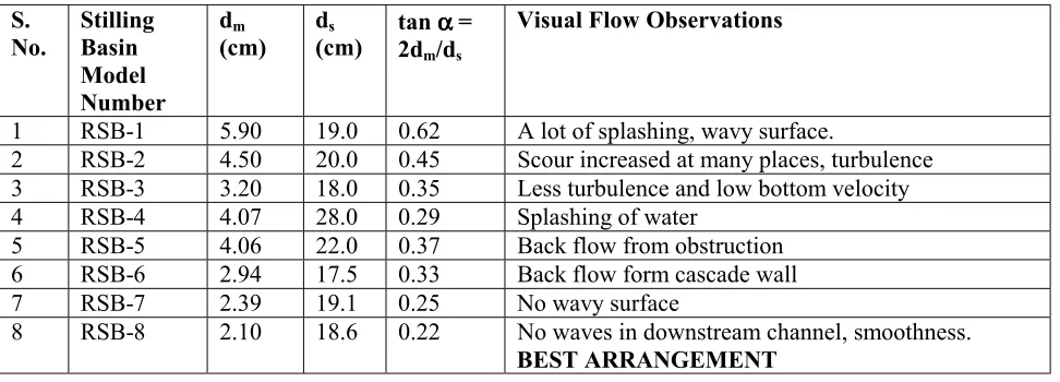
Stilling basin models SBR-1 and SBR-2 are provided with a stepped wall with vertical upstream face and a weir wall with 1H: 2V slope up to a height of 3d after the grid respectively. The value of scour index is smaller (0.45) for SBR-2, which further reduces to 0.35 for SBR-3 where the solid wall is replaced by one more grid. In this model formations of shear layers and the formation of small jets with grids result in the loss of energy
by diffusion. When the second grid is replaced by a row of wedge shaped baffle blocks as in model SBR-4, the scour index further reduces to a value of 0.29.
Tests on a solid impact wall with a gap at the bottom and a stepped wall upstream of the wedge shaped baffle blocks as in the models SBR-5 and SBR-6 show a better performance of the models SBR-6 with a scour index value of 0.33.
Stilling basin models SBR-7 and SBR-8 use only wedge shaped blocks and arrangement of the model SBR-8 (Figure 9) shows a lower value of the scour index. In the model SBR-8, the splitter block is moved a little downstream and instead of the two half baffles blocks on the sides, a clear space is left on the sides. The main jet coming out of the outlet spreaded in full width of the basin with wedge shaped splitter block. The side spacing produces stronger eddies in addition to other horizontal discontinuity layers and helps in energy dissipation as indicted by value of the lower scour index (tanα = 0.31). It means that some spacing must be left on the sides also for proper distribution of flow in full width of the stilling basin model. The depth of the scour is minimum in this model as compared to all other models. The water surface after the end sill remains smooth and
less wavy.
It is clear from the above discussion that when the wedge shaped blocks are used as a splitter or in a row of baffle blocks, the performance of the stilling basin improves as compared to other stilling basin models using appurtenances such as grid, impact wall, weir wall etc. The splitter block splits the jet and spread it into full width of the stilling basin and creates a better mixing with the surrounding fluid. The mechanism
consists of production of large-scale turbulence, which changes into small-scale turbulence during distribution. This results into additional momentum transfer in the lateral and vertical directions. The energy is dissipated in both vertical and horizontal direction with shear drag, pressure drag and diffusion. The sloping end sill deflects the bottom current the surface and induces a ground roller, which deposits the bed material at the downstream face of the end sill.
7. COMPARISON OF NEW RECOMMENDED MODEL WITH USBR TYPE VI STILLING
BASIN MODEL
The USBR impact type VI stilling basins are generally provided for circular outlets and floor of the stilling basin is kept below the invert level of the outlet. The size of the stilling basin is estimated
for Froude number Fr = 4.89 and width and length of stilling basin model for USBR impact type VI stilling basin based on Bradley and Peterka [1] are 41.17cm and 54.76cm respectively.
The proposed width and length of stilling basin for the deep rectangular outlets are 15.24cm and 30.40cm respectively, which are much smaller as compared to USBR impact type VI stilling basin.
Figure 10. Assumed parabolic scour profile.
TABLE 1. Scheme of Experimentation Along with Results of Stilling Basin Models Tested for Fr = 3.68, Size of Opening Width = 2.54cm (d), Depth = 10.16cm (4d)
S. No.
Stilling Basin Model Number
dm
(cm) ds
(cm) tan 2dm/dαααα = s
Visual Flow Observations
1 RSB-1 5.90 19.0 0.62 A lot of splashing, wavy surface.
2 RSB-2 4.50 20.0 0.45 Scour increased at many places, turbulence 3 RSB-3 3.20 18.0 0.35 Less turbulence and low bottom velocity 4 RSB-4 4.07 28.0 0.29 Splashing of water
5 RSB-5 4.06 22.0 0.37 Back flow from obstruction 6 RSB-6 2.94 17.5 0.33 Back flow form cascade wall 7 RSB-7 2.39 19.1 0.25 No wavy surface
8. CONCLUSIONS
Following conclusions have been drawn on the basis of the present study:
1. The performance of the stilling basin can be evaluated by using same material and a constant run time for all test runs on different models and comparing the values of scour index.
2. The wedge shaped splitter block mainly helps in lateral spreading of the narrower jet in a shorter length of the basin.
3. A row of wedge shaped blocks assisted in more energy dissipation as indicated by lower values of the scour indices.
4. The recommended stilling basin for deep rectangular outlets is much smaller in dimensions as compared to USBR Impact type VI stilling basin, making it economical.
9. NOTATION
The following symbols are used in this paper: d = width of rectangular outlet;
de = equivalent diameter of the rectangular outlet;
dm = maximum depth of scour;
ds = distance of maximum depth of scour after end sill;
Fr = Froude number of pipe outlet; g = acceleration due to gravity; hb = height of wedge shaped block;
sb = spacing between wedge shaped blocks;
sc = end spacing between wedge shaped block and wall of the channel;
y = diameter of circular outlet; V = efflux velocity of the jet; and wb = width of wedge shaped block; tanα = scour index = 2dm/ds.
10. REFERENCES
1. Bradely, J. N. and Peterka, A. J., “Hydraulic Design of Stilling Basins”, Journal of Hydraulic Division, ASCE, (1957), 1401-1406.
2. Fiala, J. R. and Maurice, L. A., “Manifold Stilling Basin”, Journal of Hydraulic Division, ASCE, Vol. 87, (1961), 55-81.
3. Vipun, R., “Stilling Basins with Side Expansion for Outlet Works”, MTech Thesis Kurukshetra University, Kurukshetra, (1992).
4. Pillai, N. N. and Goel, A., “Hydraulic Jump Type Stilling Basins for Low Inflow Froude Numbers”,
International Journal of Hydraulic Eng. Division,
ASCE, Vol. 115, (1989), 989-994.
5. Pillai, N. N. and Goel, A., “Stilling Basins for Low Froude Number using Wedge Shaped Blocks”, Ninth Congress of Asian & Pacific Division of I.A.H.R., Singapore, (1994).
6. Verma, D. V. S. and Goel, A., “Modified Design of U.S.B.R. Stilling Basin for Outletworks”, Ninth Congress of Asia Pacific Division, I.A.H.R., Gadjah Mada University, Yogyakarta, Indonesia, (1998). 7. Verma, D. V. S. and Goel, A., “Stilling Basins for
Pipe Outlets using Wedge Shaped Splitter Block”,
International Journal of Irrigation and Drainage Eng. Division, ASCE, Vol. 126, No.3, (May/June 2000), 179-184.