Please cite this article as: V. Morenov, E. Leusheva, Development of Drilling Mud Solution for Drilling in Hard Rocks, International Journal of Engineering (IJE), TRANSACTIONS A: Basics Vol. 30, No. 4, (April 2017) 620-626
International Journal of Engineering
J o u r n a l H o m e p a g e : w w w . i j e . i rDevelopment of Drilling Mud Solution for Drilling in Hard Rocks
V. Morenov*a, E. Leushevab
a Saint-Petersburg Mining University, Electromechanical Department, Saint Petersburg, Russia b Saint-Petersburg Mining University, Oil and Gas Department, Saint Petersburg, Russia
P A P E R I N F O
Paper history:
Received 05 December 2016
Received in revised form 22 February 2017 Accepted 10 March 2017
Keywords: Drilling Mud Hard Rocks Microfractures Rock Destruction Surfactant
A B S T R A C T
Aim of the project is efficiency increase of hard rocks destruction at borehole bottom by developing drilling mud solution and evaluation of its influence on drilling process. The article presents the results of studies directed on studying of drilling mud composition (the choice of reagent concentrations, taking into account the filtration properties, structural and rheological parameters, study of the temperature effect influence on the quality of the solution). Experiments of metallic indenter penetration into the glass sample at various number of strikes in the water and surfactant solutions are presented in the article. Paper also offers investigation devoted to development of clayless mud solution with surfactant addings, which will allow increase of hard rocks destruction efficiency. Results of industrial test trials of developed mud solution are also represented, showing implementation of developed drilling mud composition to increase productivity of drilling operations by maintaining high drilling speed and advance per bit.
doi: 10.5829/idosi.ije.2017.30.04a.22
1. INTRODUCTION1
While constructing wells at hard rocks it is important to know how content and properties of drilling mud influence hard rocks drilling capability.
Technical literature reviews rocks drilling capability as its resistance to destruction by bit or by other rock-destructing equipment. Rocks drilling capability is defined by drilling speed value or advance per bit [1].
Some of the scientists consider drilling capability to be heavily influenced by hydrostatic and bottom-hole pressure. At the same time it is noted that pressure differential is defined by physical properties of drilled rocks, properties and content of drilling mud, its chemical treatment, solids content etc. Others claim that main factors of hard rocks drilling capability are filtration, mud filtrate contains, viscosity, structural and mechanical properties of washing fluid.
Destruction of rocks can be facilitated using the Rebinder effect – adsorption reduction of solid bodies’ durability. This effect is to reduce the surface energy by means of surface-active substances (surfactants), as a
*Corresponding Author’s Email: [email protected](V. Morenov)
result of which, deformation and destruction of the solid bodies occur easier. Hardness reducers are used as such surfactants [2, 3].
Lowering rock hardness using surfactant largely depends on the conditions and the type of rock destruction by bit. Surfactants are most effective at brittle rock destruction by bit when in the bore bottom zone macro- and microfractures are developing. Surfactants, penetrating into the fractures of bore bottom, prevent them from closing at short-period load removal. With each successive hit of the bit tooth at the rock previously formed fractures develop with the emergence of new defects in the structure of the destructed rocks. This causes the formation of pre-destruction zones at the bore bottom, thus facilitating drilling of the rocks. This effect has significant impact at drilling in solid rocks [3, 4].
In addition to the introduction of hardness reducers into the drilling mud one should try to achieve reduction of suppressive pressure on the bottom of the well. This can be done by lowering the density of the solution (for example, using clayless compositions based on various polymer reagents, including biopolymers widespread in recent years) [5, 6].
Authors have conducted research on surfactant type selection before, based on interface angle measurement and acquiring rock sample deformation chart in various surfactants meduim, which revealed high efficiency of anion-active surfactants [7, 8].
2. METHODS AND TECHNIQUES
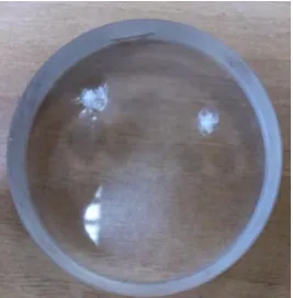
To visualize efficient results of surfactants implementation, series of experiments were conducted involving penetration of metallic indenter into the glass sample at various number of strikes in the water and surfactant solutions.
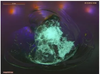
Glass was chosen as an object of investigation because of its isotropic properties. Figures 1, 3 and 4 show the results of brittle deformation after 5 hits of indenter (Figure 2) on glass sample surface in water medium and anion-active surfactant solution (sodium lauryl sulfate).
The operation principle of indenter’s spring mechanism is based on compression and an instantaneous release of the spring. The frame is made of three parts 3, 5 and 6, where springs 7 and 11 are placed, along with the shaft 2 and indenter 1, striking pin 8 with shifting liner 10 and the leaf spring 4. When the edge of the indenter is pressed, inner end of the rod 2 abuts in a liner, causing the striking pin to move up and compress the spring 7. Leaning against the edge of the shoulder 9, liner is shifted to the side and its edge goes out of the rod 2. At this point striking pin, forced by the compressed spring 7, strikes the end of the rod with indenter. Immediately after that, spring 11 restores the initial position of the indenter. Strike force (10 - 15 N) is adjusted by screwing or unscrewing the cap 6. Investigated solution is fed into the contact zone.
Based on acquired data conclusion was drawn so at single indenter hit increase in destruction zone at 0.1% anion-active surfactant solution is 50% higher than those at water solution.
Figure 1. Image of glass sample surface after 5 hits of
indenter (general view)
With increasing number of hits (3,5,6,8) this difference is 25-35% (Figures 3 and 4).
Main indicators of drilling mud properties (density, viscosity, filtration index, content and composition of the solid phase) depend primarily on the component composition. There is no material for drilling fluids which would solely selectively affect the performance properties of the prepared system. With increase of solid phase content density rises, but the filtration index decreases. Processing of solutions with polymers to decrease the index of filtration is accompanied by increasing of the system viscosity. Diluting of drilling mud usually increases its filtering parameters, and liquefaction results in dispersion of clay phase and rise of filtrate viscosity [9, 10]. Thus, main indicators of drilling mud technological properties are interrelated.
Figure 2. Indenter scheme; 1 – indenter; 2 – rod; 3, 5, 6 –
frame parts; 4 – leaf spring; 7 – spring; 8 – striking pin; 9 – shoulder; 10 – shifting liner; 11 – spring; 12 – glass sample with created dent
Figure 3. Image of glass sample surface after 5 hits of
Figure 4. Image of glass sample surface after 5 hits of indenter in anion-active surfactant solution
However, through a combination of reagents it is possible to selectively regulate any parameter while fixing the rest. Therefore, it seems appropriate to consider the influence degree of the main technological parameters on the drillability of rocks and drilling speed.
Next, research stage was dedicated to development of clayless mud solution with main components of xanthate bio-polymer “KK-Robus”, reagent based on acrylic polymers and anion-active surfactant composition.
Table 1 represents the results of solutions main parameters measurements with various bio-polymer concetrations.
Bio-polymer solutions have lesser density than clay solutions, what in return increases efficiency of hard rocks destruction [1, 11, 12].
Meanwhile viscosity of clay drilling muds is always desired to be lowered due to lesser energy expenditures on mud circulation, better borehole bottom cleansing, higher hydraulic power on the bit, decreased pressure losses in well annular space [13, 14].
TABLE1. Technological parameters of bio-polymer solutions
Mass concentrati on of
reagent Den
si ty , k g /m V isco si ty ra ti o , s S S S a ft er 1 0 mi n , d P a F lu id r et u rn i n 3 0 mi n , cm 3 P la st ic v isc o si ty , mP a∙ s D y n ami c sh ea r st re ss, P a 0.1%
“KK-Robus” 1005 17 1 31 1.5 2
0.2%
“KK-Robus” 1005 18 1 27 2 2.5
0.3%
“KK-Robus” 1005 19 1.5 20 3 4.5
0.5%
“KK-Robus” 1010 43 10 9 5 5.6
0.7%
“KK-Robus” 1015 85 14 6 10 12.7
For bio-polymer solutions, this requirement can be not so critical because of their thinning property at high shear rate [15]. Viscosity ratio of investigated solutions (Figure 5) ranges from 17 to 85 s.
Next parameter, which characterizes the quality of drilling mud, is degree of fluid return [16-18]. Fluid return of solutions with bio-polymer content from 0.1 to 0.3% is much higher than those with concentration from 0.5 to 0.7% (Figure 5). Static shear stress (SSS) should be minimal, but enough for keeping particles of drilled rocks and heaver in the motionless drilling mud at fluidised state [19, 20].
Figure 6 shows that bio-polymer solutions’ index of SSS variates from 1 to 14 dPa. SSS values of three solutions are very low. It is known that dynamic shear stress (DSS) is a force needed to be applied to solution to cause its streamlined flow, so it is unfeasible to increase value of dynamic shear stress.
Figure 5. Dependance of viscosity ratio and fluid return from
bio-polymer “KK-Robus” concentration
Figure 6. Dependance of SSS and DSS from bio-polymer
One can see (Figure 6) that while concentration of bio-polymer increases to 0.7% DSS value reaches 12.7 Pa. Obtained results show that correct concentration of xanthate bio-polymer “KK-Robus” for further investigation should be no less than 0.3% and no higher than 0.6%.
3. INVESTIGATION
At the optimal concentration selection of acryl polymer “K-M017”, it was found that polymer concentration increase to 7-9% (with content of “KK-Robus” 0.4%) leads to growth of reological and structural factors, e.g. solution viscosity rose to 80 s. Based on common considerations, the most suitable drilling mud for borehole cleansing and reducing of pressure losses is the one with mostly structural viscosity, i.e. with high ratio of ultimate dynamic shear stress to the plastic viscosity or low nonlinearity index [21-23].
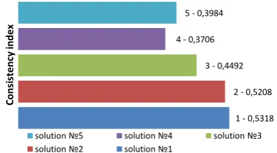
Therefore, experiments were conducted considering nonlinearity index of various drilling mud compositions (Table 2) with the use of rotational viscosimeter “Rheotest”: Nonlinearity indices of investigated drilling mud solutions are presented on Figure 7.
As can be seen, compositions of solutions 1, 2 and 3 have high values of nonlinearity, what leads to increase pressure losses in the well and decrease efficiency of borehole bottom cleansing, which in turn lowers overall efficiency of drilling.
Solutions 4 and 5 have acceptable indices of nonlinearity. However, at adding into the solution „Konkrepol
TABLE2. Compositions of drilling mud solutions
Solution № Mud composition
№1 0.3% “KK-Robus” + 2% „K-M017” + 0.1% surfactant
composition + 0.1% NaOH;
№2 0.3% “KK-Robus” + 1.5% „K-M017” + 1.5%„
Konkrepol - B“ + 0.1% surfactant composition + 0.1% NaOH;
№3 0.4% “KK-Robus” + 3.5% „K-M017” + 0.1%
surfactant composition+ 0.1% NaOH;
№4 0.3% “KK-Robus” + 2% „K-M017” + 3% „Konkrepol
- B“ + 0.1% surfactant composition + 0.1% NaOH;
№5 0.4% “KK-Robus” + 5% „K-M017” + 0.1%surfactant
composition+ 0.1% NaOH.
Figure 7. Nonlinearity indices of investigated drilling mud
solutions
- B“ (solution 4) reological parameters exceed allowable level (for example, viscosity ratio was 90 s).
Concentration of anion-active surfactants in the developed solution was chosen due to earlier conducted experiments [6, 24] and corresponds 0.1%. To lower water hardness 0.1% sodium hydrate (caustic soda) is introduced into the solution.
From mentioned above a conclusion can be made, that bio-polymer drilling mud will have following parameters (Table 3):
Flow of drilling mud (in the drilling string) while moving is heated by up-going stream of drilling mud (through the walls of drilling strings), that is why it has minimum temperature at the well top and maximum temperature at the bit’s outlet, with other equal conditions the temperature rises with depth of the well [25].
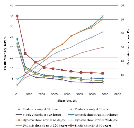
Due to this fact research of structural and reological indices of developed clayless drilling mud at various ambient air temperatures was conducted, as well as investigation of plastic viscosity and dynamic shear stress at temperature range from 30 to 120 °C.
Acquired dependences of plastic viscosity and DSS from shear rate at various temperatures are presented on Figure 8. As can be seen on the figure with temperature growth both plastic viscosity and DSS are decreasing.
It follows from the charts that at shear rate of 6700 1/s and temperature increase to 90 °C decrease of plastic viscosity is 22% from readings at 30 °C, and at heating the surroundings to 120 °C – 42%. Same dependences are observed at data analysis of DSS, that is 22% at heating to 90 °C and 42% at further temperature increase to 120 °C.
TABLE3. Parameters of drilling mud composition
Mud (Mud composition)
Parameters
Density,
kg/m3 Viscosity, s
Filtration index,
cm3/30 min DSS, Pa
SSS 1/10,
Pa pH
- 0.4% “KK-Robus”; - 5% acryl polymer „K-M017”; - 0.1% anion-active surfactant (0.05% sodium laurel sulfate and 0.05% potassium acetate); - 0.1% NaOH.
1010-1015 19-21 5.5-6.5 5-6 2/7-3/9 8-9
1 - 0,5318 2 - 0,5208 3 - 0,4492 4 - 0,3706
5 - 0,3984
C
ons
is
te
ncy
inde
x
solution №5 solution №4 solution №3
Figure 8. Dependence of plastic viscosity and DSS from shear rate at various temperatures
This can be explained by the fact that at high temperatures thermal oxidative degradation of polymers in the content solution occurs. At the same time high-viscosity types transform into high-viscosity and mid-viscosity into low-mid-viscosity.
4. DISCUSSION
Investigation results show that at high temperature of ambient air structural and reological parameters of developed clayless bio-polymer drilling mud stay in the allowable limits and thus can be used at deep wells drilling.
For efficiency evaluation of developed bio-polymer solution in field conditions industrial test trials were carried out at well drilling in hard rocks on Gimmelfarb oilfield (Zambyl region, Kazakhstan) and Taloveys site (Karelia republic, Russia).
On Taloveys site trials were carried out on wells № 115 with depth of 54.4 m and № 113 with depth of 98.8 m, column of which is comprised mostly by
diorite-granodiorite-granite structures (X and XI drillability indices).
On Gimmelfarb oilfield trials were done on wells 2GF with depth of 502 m and well 7GF with depth of 258 m. Geological column of this oilfield consists of quarternary, paleogene and carbonic deposits which are comprised by the following materials. Clay loams, sand clays, sands, clays, sandstones, siltstones etc. of III-IV drillability indices. Next ordovician and middle cambrian deposits, comprised by light-dark-grey and dolomitic limestone, black, dark-grey and grey dolomites of XI – XII drillability indices. Middle and lower cambrian deposits of phosphate ores were also comprised by various phosphorites of carbonate type with rare layers of phosphate siliceous shales, XI drillability index.
The object of research on this field were the layers comprised by rocks of XI - XII drillability indices.
On these wells bio-polymer clayless solution with following characteristics (Table 4) was used as an alternative to process water.
During drilling, solution had stable properties. Its filtration, structural and rheological properties have not changed at the purification of sludge.
Consumption of chemical reagents and materials did not exceed the norm. Preparation of the proposed solution at the drilling rig didn’t require additional special equipment and did not cause technical difficulties. Technology of solution preparation was in adhering to the percentage ratio and sequence of reagents injection into the drilling mud.
5. RESULTS
Positive gains were obtained as a result of conducted industrial test trials, which are reflected in the Table 5. Results of conducted research indicate that properties and composition of the drilling mud influence the process of hard rocks destruction. Implementation of clayless drilling mud with additives of anion-active surfactant compositions can raise the efficiency of drilling operations by increasing the penetration rate and the advance per bit.
TABLE4. Parameters of bio-polymer clayless solution
Mud (Mud composition)
Parameters
Density, kg/m3 Viscosity, s Filtration index, cm3/30
min pH
- “KK-Robus”; - acryl polymer „K-M017”; - anion-active surfactant
TABLE5. Results of conducted industrial test trials
Parameters Taloveys site Gimmelfarb oilfield
Well № 115,
№ 113 Well 2GF Well 7GF
Increase in
penetration rate, % 24-27 22 18
Increase in advance
per bit, % 20 15 15
6. REFERENCES
1. Fakhru’l-Razi, A., Pendashteh, A., Abdullah, L.C., Biak,
D.R.A., Madaeni, S.S. and Abidin, Z.Z., "Review of technologies for oil and gas produced water treatment", Journal of Hazardous Materials, Vol. 170, No. 2, (2009), 530-551. 2. Allen, T.O. and Roberts, A.P., "Production operations: Well
completions, workover, and stimulation. Volume 1", (1978). 3. Rehbinder, P., Schreiner, L. and Zhigach, K., "Hardness
reducers in drilling", Academy of Science, Moscow, Vol. 194, No. 4, (1944).
4. Ahmadi, M.A. and Shadizadeh, S.R., "Induced effect of adding nano silica on adsorption of a natural surfactant onto sandstone
rock: Experimental and theoretical study", Journal of
Petroleum Science and Engineering, Vol. 112, (2013), 239-247.
5. Caenn, R. and Chillingar, G.V., "Drilling fluids: State of the art", Journal of Petroleum Science and Engineering, Vol. 14, No. 3-4, (1996), 221-230.
6. Morenov, V. and Leusheva, E., "Energy delivery at oil and gas wells construction in regions with harsh climate", International Journal of Engineering-Transactions B: Applications, Vol. 29, No. 2, (2016), 274.
7. Berguerand, N. and Lyngfelt, A., "The use of petroleum coke as fuel in a 10kw th chemical-looping combustor", International Journal of Greenhouse Gas Control, Vol. 2, No. 2, (2008), 169-179.
8. E.L., L. and V.A., M., "Combined oilfield power supplying system with petroleum gas utilization as an energy carrier",
Neftyanoe Hozyajstvo - Oil Industry, Vol., No. 5, (2015), 96-100.
9. Bretz, J. and Cech, L.S., Aqueous well-drilling fluids. (1980), Google Patents.
10. Lummus, J.L., Low solids drilling fluid. (1971), Google Patents.
11. Feenstra, R. and Zijsling, D., "The effect of bit hydraulics on bit performance in relation to the rock destruction mechanism at depth", in SPE Annual Technical Conference and Exhibition, Society of Petroleum Engineers., (1984).
12. Bazmi, A.A. and Zahedi, G., "Sustainable energy systems: Role of optimization modeling techniques in power generation and
supply—a review", Renewable and Sustainable Energy
Reviews, Vol. 15, No. 8, (2011), 3480-3500.
13. Schormair, N., Thuro, K. and Plinninger, R., "The influence of anisotropy on hard rock drilling and cutting", The Geological Society of London, IAEG, Paper, Vol., No. 491, (2006), 1-11. 14. Moradi, S.T. and Nikolaev, N., "Optimization of cement spacer
rheology model using genetic algorithm (research note)",
International Journal of Engineering-Transactions A: Basics, Vol. 29, No. 1, (2016), 127-133.
15. Jimeno, E.L., Jimino, C.L. and Carcedo, A., "Drilling and blasting of rocks, CRC Press, (1995).
16. Moradi, S.S.T. and Nikolaev, N.I., "Considerations of well
cementing materials in high-pressure, high-temperature
conditions", International Journal of Engineering,
Transactions C: Aspects, Vol. 29, No. 9, (2016), 1214-1218. 17. Staroselsky, A. and Kim, K., "An analytical elucidation of the
influence of surfactant on rock drilling by shear/drag bit", Rock Mechanics and Rock EngineerinG, Vol. 30, No. 3, (1997), 145-159.
18. Rehbinder, P.A. and Shchukin, E.D., "Surface phenomena in solids during deformation and fracture processes", Progress in Surface Science, Vol. 3, (1972).
19. Gao, H. and Liu, H.-t., "Concept design for drilling fluid cooling system [j]", Oil Field Equipment, Vol. 6, (2007).
20. Gill, J., "Hard rock drilling problems explained by hard rock pressure plots", in IADC/SPE Drilling Conference, Society of Petroleum Engineers. (1983).
21. Kawale, D., "Influence of dynamic surface tension on foams: Application in gas well deliquification", MSc. Thesis. Delft University of Technology of Applied Sciences Department of Multi-Scale Physics, (2012),
22. Lays, R. and Grayson, E.S., "Performance gains realized with pdc bits in air/foam applications in the appalachian basin", in SPE Eastern Regional/AAPG Eastern Section Joint Meeting, Society of Petroleum Engineers., (2008).
23. Drop shape analysis system «easydrop». Application guide / kruss, gmbh, hamburg, (2007), 147 p.
24. Nikolaev, N. and Leusheva, E., "Increasing of hard rocks drilling efficiency (russian)", Oil Industry Journal, Vol. 2016, No. 03, (2016), 68-71.
Development of Drilling Mud Solution for Drilling in Hard Rocks
RESEARCH NOTEV. Morenova, E. Leushevab
a Saint-Petersburg Mining University, Electromechanical Department, Saint Petersburg, Russia b Saint-Petersburg Mining University, Oil and Gas Department, Saint Petersburg, Russia
P A P E R I N F O
Paper history:
Received 05 December 2016
Received in revised form 22 February 2017 Accepted 10 March 2017
Keywords: Drilling Mud Hard Rocks Microfractures Rock Destruction Surfactant
ديكچ ه
هعسوت لاح رد یاه هنامگ نییاپ رد تخس گنس بیرخت یرو هرهب شیازفا ،هژورپ نیا زا فده و یرافح لگ لولحم
تسا یرافح دنور رب نآ ریثات یبایزرا
.
لگ بیکرت هعلاطم یور هدش ماجنا تاعلاطم زا لصاح جیاتن یانبم رب هلاقم نیا
هجرد رثا ریثات هعلاطم ،یکیژولوئر و یراتخاس یاهرتماراپ ،نویسارتلیف صاوخ هب هجوت اب ،فرعم تظلغ باختنا( یرافح )لولحم تیفیک یور رب ترارح .دشاب یم
فلتخم یاه هرامش رد یا هشیش هنومن هب یزلف هدنورورف ذوفن یاه شیامزآ
.تسا هدش هئارا هلاقم رد تناتکافروس یاه لولحم و بآ رد تاباصتعا لگ لولحم هب هدش هداد صاصتخا یسررب زین ذغاک
سر کاخ نودب ندرک هفاضا اب
یرو هرهب شیازفا هب هک دهد یم هئارا ار تناتکافروس تخس گنس بیرخت
دهاوخ هزاجا
لگ بیکرت یارجا هک ،تسا هدش هداد ناشن زین هتفای هعسوت لگ لولحم زا یتعنص تست شیامزآ زا لصاح جیاتن .داد یم ناشن تیب ره دربشیپ و یرافح لااب تعرس ظفح اب یرافح تایلمع یرو هرهب شیازفا یارب ار هتفای هعسوت یرافح .دهد