www.adv-radio-sci.net/4/179/2006/ © Author(s) 2006. This work is licensed under a Creative Commons License.
Advances in
Radio Science
Cordic based algorithms for software defined radio (SDR)
baseband processing
B. Heyne and J. G¨otze
University of Dortmund, Information Processing Lab, Otto-Hahn-Str. 4, 44227 Dortmund, Germany
Abstract. This paper presents two Cordic based algorithms
which may be used for digital baseband processing in OFDM and/or CDMA based communication systems. The first one is a linear least squares based multiuser detector for CDMA incorporating descrambling and despreading. The second al-gorithm is a pure Cordic based FFT implementation. Both algorithms can be implemented using solely Cordic based architectures (e.g. coprocessors or ASIPs). The algorithms exactly fit the needs of a multistandard terminal as they both are freely parameterizable. This regards to the accuracy of the results as well as to the parameters of the performed func-tion (e.g. size of the FFT).
1 Introduction
A lot of modern signal processing applications require such a high computational power that only ASICs can fulfill the technical demands. Unfortunately, ASICs are inflexible, costly (development and debugging) and only economical for mass-products. As a consequence, system designers are striving to replace specialized hardware solutions with soft-ware based solutions as developments in the field of softsoft-ware radio demonstrate. Due to the fact that even the most com-monly used programmable devices, i.e. DSPs, often lack the required processing power, one tries to develop a solu-tion that lays somewhere in between the two extrema pro-grammable signal processing and dedicated hardware. The efforts in this area are summarized with the term reconfig-urable computing.
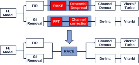
We are using this approach to create a common software defined baseband implementation for UTRA/UMTS-FDD and WLAN as shown in Fig. 1. The most computational in-tensive tasks are performed on a dedicated hardware
acceler-Correspondence to: B. Heyne
FE Model
FIR
FFT
GI Removal
Channel correction
RAKE ChannelDemux
De-Int. Viterbi Viterbi/ Turbo
FE Model
GI Removal
RACE
Channel Demux
De-Int. Viterbi Viterbi/ Turbo
Descrmbl. Despread
FIR FE
Model
FIR
FFT
GI Removal
Channel correction
RAKE ChannelDemux
De-Int. Viterbi Viterbi/ Turbo
FE Model
GI Removal
RACE
Channel Demux
De-Int. Viterbi Viterbi/ Turbo
Descrmbl. Despread
FIR
Fig. 1. Software defined baseband processing for WLAN and UMTS using the RACE accelerator.
ator called RACE using Cordic processing elements. The im-plementation of a Cordic based the FFT and a Cordic based linear equalizer/multiuser detector for CDMA, including de-scrambling and despreading, is presented in this paper.
As the equalizer and the FFT can now be build upon solely Cordics, we have derived a software defined architecture for a mobile multi-standard terminal. The main processing blocks of the WLAN and UMTS baseband can be replaced by this programmable architecture.
The paper is organized as follows. At first the multiuser detector including the system model, algorithm and simula-tions is described in Sect. 2. Secondly the Cordic based FFT algorithm and simulation results are presented in Sect. 3, fol-lowed by an overview of the RACE coprocessor in Sect. 4. Finally the conclusions are given in Sect. 5.
2 CDMA multiuser detection
2.1 System model
½
½
Fig. 2. Block diagram of the system model.
the other users. The system model used is shown in Fig. 2. The incomingmcomplex data symbols of useri, collected in the vector di, are first upsampled by the spreading factorq,
so that one symbol now consists ofqchips. Each upsampled symbol is now convolved with an OVSF code (3GPP, 2002) contained in the vector si of lengthq. Finally, the summed
data streams are scrambled with the complex data sequence in vector c which is repeated for every data frame (38400 chips in UTRA/FDD).
The received chips are now obtained by propagating the signal through a channel, which is characterized by its com-plex valued channel impulse response vector h of lengthhl,
and adding an AWGN component n.
Therefore the received data vector r is given by
r=n+HC
u X
i=1
Sidi (1)
where H is a convolutional matrix describing the time vari-ant complex channel, C is a complex valued diagonal matrix containing the scrambling code c on its main diagonal and
Si is a block Toeplitz spreading matrix. In this matrix each
block is one column wide and contains the OVSF code for thei-th data stream.
For the proposed algorithm it is assumed that the received signal r has already passed the chip matched filter and has been sampled at chip rate. We also assume that the channel impulse response h (or the strongest taps of it) is known, as the channel estimation is not part of this paper.
2.2 Multiuser detection
The derivation of the single user detector/equalizer from this model is described in Heyne et al. (2003). For the multiuser detection we are interested in the firstj users and will treat the other users as an additional noise component, so that r is changed to
r=n0+HC
j X
i=1
Sidi (2)
with
n0=n+HC
u X
i=j+1
Sidi.
q
˜k11
˜k21 ˜k22 ˜k1j ˜k12
˜k2j
˜km
1
˜km
2
˜kmj q+hl−1
·˜dj+n=r ˜
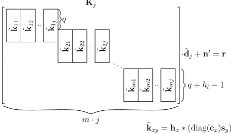
Kj
m·j
˜
kxy=hx∗(diag(cx)sy)
Fig. 3. Resulting structure of the system matrixK˜j. The∗-operator
indicates a convolution.
To describe r as a simple matrix-vector multiplication, we create a new symbol vectord˜jwhich contains the time
inter-leaved data symbols diof the firstj users ˜
dj = [d11 d12 · · · d1j d21 d22 · · · d2j · · · dmj]T ,
and a new spreading matrixS˜j containing thej
correspond-ing spreadcorrespond-ing codes.
Now the vector r can be rewritten as:
r=n0+HCS˜jd˜j (3)
When we have a close look at the structure of the matri-ces involved in the computation, we will notice that there are several characteristic properties that can be exploited to sim-plify the calculation of the data symbols. In our approach the
H,CandS˜j matrices are multiplied to get the system matrix ˜
Kjof widthm·j: ˜
Kj =HCS˜j. (4)
This matrix will be used to calculate the desired data sym-bols. The structure ofK˜j is shown in Fig. 3.
The nonzero column vectors are calculated by convolving the channel impulse response with the scrambled spreading code. cxdenotes thex-th code block of lengthqin c. As the
scrambled spreading code just has got (±1±i) entries the system matrix can be build without using multiplications.
It is obvious thatK˜j has got a very sparse structure which
can be exploited as described in Sect. 2.3, to reduce the com-putational effort to solve the linear system.
2.3 Implementation
The detection of the estimated data symbolsd˜0j can now be performed by solving the overdetermined linear system
˜
Kjd˜0j =r. (5)
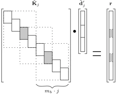
0 1
0 1
˜
Kj d˜j r
mb·j
Fig. 4. Overlapping for easier calculation.
processor array (Otte et al., 2002) using Cordic processor el-ements (PE) performing Givens transformations. But, as the structure ofK˜
j is known, a direct approach is used for the
calculation of the QR decomposition. A new system matrix is build fromK˜jand r. Then the required Givens
transforma-tions are applied only to the nonzero elements ofk˜xyinK˜j.
In each step one vectork˜
xyis annihilated. For each
anni-hilation of one element in kxy it is necessary to recompute
two rows of the matrix composed ofK˜
j and r. The last step
shows the matrix R and the vector r0which are used to
per-form the back-substitution.
2.4 Subdividing the calculation
It is obvious thatK˜jcan grow to a very large matrix. A whole
data frame ofm·j=2 400·16=38 400 symbols at spread-ing factorq=16 and a channel of lengthhl=10 would
re-quire aK˜
j matrix of size 38 409×38 400.
To overcome this problem the systemK˜jd˜0j=r is
sub-divided into overlapping subsystems of manageable size as shown in Fig. 4 and described in Vollmer et al. (2001).
The linear system is subdivided into blocks of sizemb·j.
Using this method it is possible to solve the complete sys-tem without the need to store the whole matrix which would also involve large latency and memory needs. Overlapping of the blocks is necessary, as the independent calculation of the subproblems leads to higher symbol errors at the block edges. These errors are nearly eliminated by using this over-lapping method.
This method involves a certain amount of computational overhead as the grey blocks have to be calculated twice. The overhead can be reduced by choosing larger block sizesmb.
For good results the overlapping factor should be chosen at least as high as the block overlapping factorpofK˜j.
Table 1. Computational complexity comparison.
Rake Cordic based LS
Operations
Symbol 4352 6023
2.5 Computational complexity
If the overlap method is used for a data frame withq=16,
mb=8,p=2,j=16 andm=2 400 about 400 blocks have
to be calculated for one frame. It is also assumed that the channel lengthhlis 10.
In this case the decomposition/back-substitution for each block needsapprox179 000 (real valued) Cordic operations and≈20 500 complex additions for the creation of the sys-tem matrix. Therefore the detection of a whole data-frame of
m·j=38400 symbols uses
≈1865 Cordic Operations Symbol and
≈214 Complex Additions
Symbol .
Note that there is no further descrambling/despreading necessary. Furthermore the Cordic based QR decomposition can make nearly 100% use of two parallel Cordics.
The complexity comparison of our proposed algorithm to other implementations is based on the numbers given in Nahler et al. (2002) for Rake and PIC based receivers. An equivalent of three array multipliers for one Cordic operation is used to include some overhead. Therefore a Cordic opera-tion would be equal to three operaopera-tions, and a complex addi-tion equals two operaaddi-tions. Then complexity of our approach for this example is on the same order than the conventional Rake receiver as shown in Table 1.
Of course this is only a rough estimate of the computa-tional complexity. But it shows that it is about the same as for the conventional Rake receiver, while the performance is significantly increased as shown in Sect. 2.6. For a detailed description of the algorithm and the complexity analysis see Heyne and Goetze (2005).
2.6 Simulations
Figure 5 shows the frame error rate for a 16-QAM based sys-tem withq=16,j=16, hl=10,mb=8 and p=2. The
channel is assumed to be constant throughout the simulation and contains four, randomly distributed, strong taps. Hence the Rake receiver is using four fingers.
5 10 15 20 10−3
10−2 10−1 100
SNR [dB]
BER
Rake MMSE LS
Fig. 5. Error rate for 16-QAM modulation.
3 FFT
3.1 MAC based FFT
A DFT withN input values s can be described as a matrix-vector multiplication. By exploiting the properties of the DFT matrix, operations can be greatly reduced and the well known Fast Fourier Transformation (FFT) (Oppenheim and Schafer, 1999) is derived.
The listing below shows a recursive implementation of a MAC based FFT in Matlab style.
1 f u n c t i o n y= f f t ( x , n )
2 i f n =1
3 y=x
4 e l s e
5 m=n / 2
6 w= exp (−2∗p i∗i / n )
7 om= d i a g ( 1 , w , . . . , w ˆ ( m−1 ) ) 8 z t = f f t ( x ( 0 : 2 : n−1) ,m) 9 zb =om∗f f t ( x ( 1 : 2 : n−1) ,m) 10 I m = e y e (m)
11 y = [ I m I m ; I m −I m ]∗[ z t ; zb ]
12 end
13 en d
3.2 Algorithm
To derive a Cordic based FFT we will stop the recursion at
n=2. In this case line 11 will look like:
y=
1 1 1−1
·
zt zb
(6)
¼
¼
½ Ô ¾
½ Ô ¾ ½ Ô ¾
½ Ô ¾
¼ ¼
Fig. 6. Symbol and function of one real valued Cordic.
π/4
π/4
a −b a
b ar
ai
br
bi −bi
−b
r
a
i
a
r
I
Fig. 7. Inner structure of complex Cordic type I.
The first matrix can then be decomposed to:
1 1 1−1
=
√ 2
− √
2
·
" √1 2
1 √ 2 −√1
2 1 √ 2
#
(7)
This equals a Cordic rotating the input values byπ/4, fol-lowed by a scaling of
√
2/− √
2.
As the Cordic elements are real valued but the input val-ues are complex valued, the complex Cordic operation has to be separated into real valued operations. Due to the special structure of the rotation matrix, this is quite easy to perform. If we assume two complex numbersa,b∈C, the result of the complex rotation will be (witht=1/
√
2):
t t −t t
| {z } T
·
ar +jai br +jbi
=
t (ar+br)+jt (ai+bi) t (br−ar)+jt (bi−ai)
(8)
=T ·
ar br
+jT ·
ai bi
(9) Thus the operation can be applied to the real and the imag-inary part of the input values independently, and the complex “butterfly” can be performed by using two of the real valued Cordics shown in Fig. 6. The scaling of the results can be performed at the end of the flow graph. The symbol for the resulting complex Cordic, called type I, rotating two complex valued numbers byπ/4 is shown in Fig. 7.
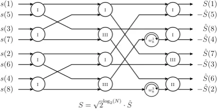
I
I
I
I
I
I
I
I
II III
III
III
w3
8
w1
8
s(8)
s(4)
s(6)
s(2)
s(7)
s(3)
s(5)
s(1) Sˆ(1)
ˆ
S(8)
−Sˆ(4)
ˆ
S(6)
−Sˆ(2)
S=√2log2(N)·Sˆ
−Sˆ(5)
ˆ
S(7)
−Sˆ(3)
Fig. 8. Optimized Cordic based FFT.
this operation can be decomposed, too. The complex Cordic performing this operation is called type II.
The structure is the same compared to the type I Cordic, except that the real valued Cordics now perform a rotation by
−3π /4.
Further optimizations are possible forwyx= −j. The re-sult of this operation can also be obtained by swapping the real and imaginary part of the input value, and then inverting the sign of the new imaginary part. A closer look at the al-gorithm reveals, that this operation is always performed on sign reversed results of the previous stage. This also implies that the result of the multiplication withw= −j is always provided to complex Cordics of type II.
Therefore the input value of the real valued Cordic is−a. Thus aw= −j multiplication followed by a type II complex Cordic can be replaced by another complex Cordic, called type III.
The final optimized version of the FFT is shown in Fig. 8. Note that there are no more twiddle factor multiplications after the first FFT stage, which saves one stage in a pipelined implementation.
The twiddle factors shown are the same as used for the standard FFT. As they are located on the unit circle, the multiplication withωxy can be replaced by a Cordic rotation directly.
It is obvious that the FFT like butterfly structure is kept. The
√
2log2(N ) scaling of the result can be performed after
the computation of the three stages. 3.3 Complexity
If N is the size of the FFT, the number of Cordic opera-tions is:
OPCordic= 3N
2 (log2(N )−1)+2 (10) The same architecture used to implement the Cordic array also provides a MAC processing element (PE) (Lange et al., 2002). This PE needs
OPMAC=(N+2)log2(N ) (11)
activations for an FFT of sizeN.
30 25
20 15
10
SNR[dB]
BER
10 Bit 12 Bit 14 Bit
Float 8 Bit
16 Bit 10−4
10−3
10−2
10−1
0.5
Fig. 9. BER for 54 MBit.
For small FFTs the operation count OPCordic is even lower than for OPMAC. For the 64-FFT used in a WLAN receiver OPCordic is 482 and OPMAC is 396. As the hard-ware accelerator currently provides two parallel PEs these numbers can be halved to get the number of accelerator acti-vations (198 for the MAC, 241 for the Cordic).
So the Cordic based FFT is slower than the MAC based implementation, but on the other hand one Cordic based re-configurable hardware architecture can now be used to im-plement the FFT for WLAN and the Rake substitute for UMTS. Also the OFDM channel correction can be imple-mented very efficiently on a Cordic, as it supports division. Hence, in the case of a FFT followed by an OFDM chan-nel correction, the computational overhead is considerably small. A more detailed description of the algorithm and it’s properties can be found in Heyne and Goetze (2004). 3.4 Simulation results
Finally, the proposed FFT has been implemented in a WLAN transmitter/receiver simulation to replace the regular FFT. The simulation shown in Fig. 9 has been performed using an AWGN channel and the coding parameters defined in IEEE Std 802.11a-1999 (1999).
The results for the 54 MBit case show that a wordlength
≥12 Bit is enough to achieve the same BER performance than the floating point FFT implementation. So the Cordic based FFT has to use just 12 Bit arithmetics to replace the standard FFT in a WLAN environment.
4 Hardware coprocessor
Table 2. Basic operations of the Cordic PE.
Mode Operation
Ortogonal xout=xincos(φz)+yinsin(φz))
Rotation yout= −xinsin(φz)+yincos(φz))
zout=zin
Ortogonal xout= q
xin2 +yin2 Vector yout=0
zout=arctan2(xin, yin)
Linear xout=xin
Rotation yout= −xinzin+yin
zout=zin
Linear xout=xin
Vector yout=0
zout=yin/xin
In our case the class of algorithms is composed of ma-trix based algorithms that can be implemented by enhanced Cordic operations. For this purpose the accelerator contains Cordic processing elements which are based on simple shift-add operations, but there are other PE types such as e.g. MACs that can be used as well. The operations that can be performed, and which are used to implement the QR decom-position of the system matrix, are given in Table 2. For ex-ample in the “Orthogonal Rotation” mode the Cordic rotates a two dimensional input vectora=(x, y)by an angleφz.
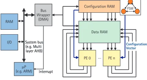
The accelerator contains several processing elements (PE) in parallel that perform the computations, a Data RAM to store values and a Configuration RAM in conjunction with a finite state-machine (FSM) to control the data flow.
Here, the RACE is embedded in a processor environment where it is connected to the system bus via a bus wrap-per, which has direct memory access (DMA) capability and thereby controls the dataflow into and out of the RACE. The processor itself is freed from all data moving tasks and is just informed by an interrupt when the results of an operation are available.
The number and the interfaces of the PEs as well as the amount and structure of the memory inside the Data-RAM can be parameterized. Hence it exactly fits the needs of the multistandard terminal where it is used.
5 Conclusions
We have presented two Cordic based algorithms usable for communication systems based on OFDM and CDMA, namely a FFT and a linear least squares based CDMA mul-tiuser detector/equalizer. The good performance and the low computational complexity of both algorithms make an im-plementation feasible.
D a t a R A M D a t a R A M
P E 0
P E 0 P E nP E n C o n f i g u r a t i o n R A M C o n f i g u r a t i o n R A M B u s
W r a p p e r ( D M A )
B u s W r a p p e r
( D M A ) B u s W r a p p e r
( D M A )
F S M F S M
m P
( e . g . A R M ) S y s t e m b u s ( e . g . M u l t i l a y e r A H B ) I / O
R A M
m P
( e . g . A R M ) S y s t e m b u s ( e . g . M u l t i l a y e r A H B ) I / O
R A M
I n t e r r u p t I n t e r r u p t
C o n f i g u r a t i o n V e c t o r
Fig. 10. Reconfigurable accelerator.
Hence, they can be used to implement a reconfigurable (software defined) architecture for multi standard terminal digital basebands, replacing dedicated hardware by using Cordic coprocessors like the RACE accelerator.
References
3GPP: TS25.213 V5.0.0 - Spreading and Modulation (FDD), Tech-nical specification group radio access network, 3rd Generation Partnership Project (3GPP), 2002.
Heyne, B. and Goetze, J.: A Cordic Based Equalizer For Multiuser Detection in WCDMA Systems, in: IEEE Workshop on Signal Processing Systems (SiPS2005), Athens, Greece, 2005. Heyne, B. and Goetze, J.: A Pure Cordic Based FFT For
Reconfig-urable Digital Signal Processing, in: 12th European Signal Pro-cessing Conference (EUSIPCO2004), Vienna, Austria, 2004. Heyne, B., Otte, M., and Goetze, J.: A Performance Adjustable and
Reconfigurable CDMA Receiver Concept for UMTS-FDD, in: 14th IEEE Intern. Symposium on Personal, Indoor and Mobile Radio Communications (PIMRC2003), Beijing, China, 2003. IEEE Std 802.11a-1999: Wireless LAN Medium Access Control
(MAC) and Physical Layer (PHY) specifications, High-speed Physical Layer in the 5 GHz Band, IEEE, 1999.
Lange, H., Franzen, O., Schr¨oder, H., B¨ucker, M., and Oelkrug, B.: Reconfigurable Multiply-Accumulate-based Pro-cessing Element, in: IEEE Workshop on Heterogeneous Recon-figurable Systems on Chip, Hamburg, Germany, 2002.
Nahler, A., Irmer, R., and Fettweis, G.: Reduced And Differential Parallel Interference Cancellation For CDMA Systems, IEEE J. on Select. Areas in Commun., 20, 237–247, 2002.
Oppenheim, A. V. and Schafer, R. W.: Discrete Time Signal Pro-cessing, Prentice-Hall, Upper Saddle River, New Jersey, third edn., 1999.
Otte, M., Goetze, J., and Buecker, M.: Matrix Based Signal Pro-cessing on a Reconfigurable Hardware Accelerator, in: 10th Dig-ital Signal Processing Workshop, Pine Moutain, Georgia, USA, 2002.