80 May, 2015 Agric Eng Int: CIGR Journal Open access at http://www.cigrjournal.org Special issue 2015
CFD model of regenerative heat exchanger
Pavel Kic
1*, Milan Zajicek
2(1. Faculty of Engineering, Czech University of Life Sciences, Prague, Czech Republic;
2. Institute of Information Theory and Automation, The Academy of Science of The Czech Republic, Prague, Czech Republic.)
Abstract: This paper is focused on the computational fluid dynamics (CFD) modeling of regenerative heat exchanger suitable for animal houses. Buildings used for housing of animals in farms with intensive breeding, like poultry or pig houses, are characterized by high generation of heat inside, partly produced by animals, and in the case of small young animals, supplemented also by heating. On the other side these buildings need intensive ventilation which causes big losses of energy by exhausted air. A good way how to reduce heat losses can be the use of technical systems of heat recovery.
There are two principal constructions of heat exchangers for heat recovery. There are either recuperative or regenerative heat exchangers. Industrially produced heat exchangers, commonly used in residential or industrial buildings, can be used in agricultural conditions only with difficulties, mainly because of the high dust concentration, which is extremely high in animal houses.
CFD modeling was used to calculate main parameters of a special heat exchanger, developed for application in animal houses. The construction of regenerative heat exchanger with fixed matrix is based on heat accumulation in material of matrix in the form of massive plates. The program Fluent was used for airflow and heat exchange simulations. Results of simulations were verified by measurement of prototype of real heat exchanger.
Keywords:animal houses, energy, parameters, ventilation, Czech Republic
Citation: Kic, P., and M. Zajicek. 2015. CFD Model of Regenerative Heat Exchanger. Agric Eng Int: CIGR Journal, Special issue 2015: 18th World Congress of CIGR: 80-93.
1 Introduction
1Buildings used for housing of animals in farms with
intensive breeding, like poultry or pig houses, are
characterized by high generation of heat inside, mainly
produced by animals, and in the case of young animals,
supplemented also by heating. On the other side these
buildings need intensive ventilation which causes large
losses of energy by exhausted air. A good way to reduce
heat losses can be the use of heat recovery technical
systems (Kic and Gurdil, 1999; Kic and Pavlicek, 2006a;
Kicet al., 2007). Whereas in recuperators, where heat is
transferred directly and immediately through a partition
wall of some kind, from a hot to a cold fluid, both of
which flow simultaneously through the exchanger, the
operation of the regenerative heat exchanger involves the
Received date: 2014-11-25 Accepted date: 2015-01-07
*Corresponding author: Pavel Kic, Faculty of Engineering, Czech University of Life Sciences, Kamýcká 129, 165 21 Prague, Czech Republic. Email: kic@tf.czu.cz
temporary storage of the heat transferred in a packing
which possesses the necessary thermal capacity.(Willmott
2011) One consequence of this is that in regenerative heat
exchangers or thermal regenerators, the hot and cold
fluids pass through the same channels in the packing,
alternately, both fluids washing the same surface area. In
recuperators, the hot and cold fluids pass simultaneously
through different but adjacent channels.
In thermal regenerator operation the hot fluid passes
through the channels of the packing for a length of time
called the "hot period," at the end of which, the hot fluid
is switched off. A reversal now takes place when the cold
fluid is admitted into the channels of the packing, initially
driving out any hot fluid still resident in these channels,
thereby purging the regenerator. The cold fluid then flows
through the regenerator for a length of time called the
"cold period," at the end of which the cold fluid is
switched off and another reversal occurs in which, this
time, the hot fluid purges the channels of the packing of
May, 2015 Agric Eng Int: CIGR Journal Open access at http://www.cigrjournal.org Special issue 2015 81
During the hot period, heat is transferred from the hot
fluid and is stored in the packing of the regenerator. In the
subsequent cold period, this heat is regenerated and is
transferred to the cold fluid passing through the
exchanger.
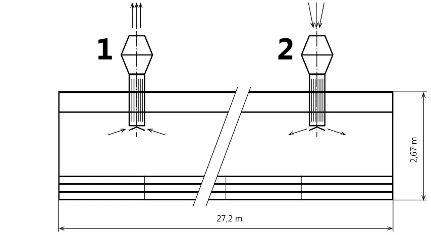
A cycle of operation consists of a hot followed by a
cold period of operation together with the necessary
reversals as can be seen at Figure 1. After many cycles of
identical operation, the temperature performance of the
thermal regenerator in one cycle is identical to that in the
next. When this condition is realized, the heat exchanger
is said to have reached "cyclic equilibrium" or "periodic
steady state." Should a step change be introduced in one
or more of the operating parameters, in particular, the
flow rate and entrance temperature of the fluid for either
period of operation, or the duration of the hot and cold
periods, the regenerator undergoes a number of transient
cycles until the new cyclic equilibrium is reached.
Earlier work (Pavlicek, 2007), presented results of the
regenerator’s measurement at the laboratory and also
under real conditionsinpig and poultry farms. The unique
design is presented there with its theoretical background
(Kic and Pavlicek, 2006a; Kic and Pavlicek, 2006b; Kicet
al., 2007). Regenerator is made from non-metallic
materials (CETRIS and CEMVIN - cement-bonded
particleboards), which are characterized by relatively
high thermal capacity and low thermal conductivity.
Numerical simulation process presented here is the
methodological attempt to obtain relevant information of regenerator’s thermal behavior. The aim is to obtain the
possibility to solve non-stationary state of equipment for
the changeable flow and thermal conditions. Obtaining
such information will lead to acceleration of the design
process of such kind of equipment for the next scheduled
cases.
2 Materials and methods
2.1 Experimental apparatus
Experimental apparatus is a rectangular channel
equipped with plate regenerator, axial fan with the flow
direction reversion capability and regulation of rotor
revolutions.
82 May, 2015 CFD model of regenerative heat exchanger Special issue 2015
Measurements were taken using an Ahlborn Almemo
2290-8 data logger equipped with thermistor sensors,
which are fixed inside the apparatus and also directly
inside the heat accumulation plates. Such configuration is
usable for obtaining time dependences of temperature for
different flow conditions and plate sizes, thanks to the
possibility of their replacement and position adjustment.
2.2 Theoretical background
Heat transfer inside a heat regenerator is a relatively
complex problem characterized as a time dependent
problem including convection and conduction principles
along with geometrically dependent surface temperature
of plates due to heating/cooling from the flowing air
stream. Due to the relatively small heat transfer
coefficient and thermal conductivity (for CEMVIN
k=0.35 W/mK and
=20 W/m2K) the Biot number for the plate is about 0.2, which means that the plate isn’theated uniformly. The temperature profile through the
thickness of the plate has not negligible differences of
temperatures between center and the surface of the plate.
The time dependent temperature profile arising inside the
material of plates is time dependent.It is therefore
impossible to use simple analytical integral methods to
predict an amount of heat accumulated/released from the
plates. Non trivial analytical solution very close to this
problem, but only for one plate can be found in Mladin
(2011) and Cafagni(2013).
2.3 Computational model for ANSYS/Fluent
Computational model is based on the experimental
apparatus dimensions. ANSYS/Design Modeler is used to
generate a rectangular channel (Figure 3). The size of
plates and the size of channel cross-section correspond
exactly to the experimental apparatus. The only visible
change is the higher total length of a channel. It is chosen
due to better distribution of air between plates, to make it
uniform as much as possible. Complete geometrical
model is made as a parametrical and therefore the
relatively long time of preparing this model is
compensated with possibility to obtain different
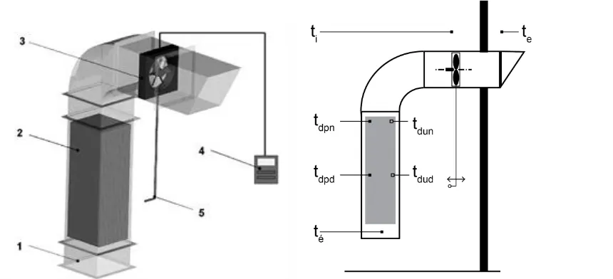
geometrical variants of this topology relatively quickly. Figure 2Heat regenerator with cement-bonded particleboards and position of specific physical characteristics
of system. 1-air inlet, 2- heat accumulating plates, 3 – fan, 4 – flowrate control, 5 – reverse of airflow directionti – internal temperature, te – external temperature, té – inside exhaust/inlet temperature, tdpntdpd – upper
and central temperature on the surface of the plate, tduntdud – upper and central temperature in the center of the
May, 2015 Agric Eng Int: CIGR Journal Open access at http://www.cigrjournal.org Special issue 2015 83
2.3.1 Geometry and Computational Grid Creation
The important problem with numerical analysis arises
after a numerical experiment with the grid generated
directly from ANSYS/Meshing software, because of the
great ratio between length of the slit and its width.
Automatic grid generator does not suffice to construct the
grid with their quested details, uniformity and acceptable
size. The great problem of this topology is that even a
small difference among the computational grid shape in
any slit leads to a significant non-uniformity in velocity
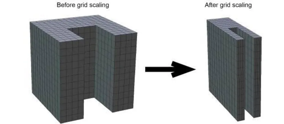
profile (flowrate) through this slit. Therefore, ascaling
grid method is proposed (Figure 4). The universal
geometry (long channel of rectangular cross-section) was
created with parametrically adjusted size and number of
plates, which are placed equidistantly, exactly at the
centre of channel. The grid sizing in one direction is
performed and requested shape with regular mesh is
obtained.
Figure 3 Computational domain,with geometrical parameters and resulting shape of computational grid
84 May, 2015 CFD model of regenerative heat exchanger Special issue 2015
The geometrical shape is three times symmetrical,
assuming, that plates are inserted onto channel
symmetrically. There are only two symmetries from
physical point of view, because there is no symmetry in
longitudinal direction for temperature profile. Finally the
inapplicability of the symmetry boundary conditions was
observed during first set of numerical simulations. Very
poor convergence of solution was also observed when
symmetry boundary conditions were used.
Also, the two dimensions model is not acceptable for
this simulation, because it cannot calculate the total
amount of energy accumulated inside plates and the
spatial distribution of monitored quantities. Therefore, a
complete domain is used for calculation. Table 1 shows
the configuration parameters used for one given
frequency of the flow direction reversion.
2.3.2 Boundary Conditions
Simulation was run under the same conditions as
laboratory measurements so as to be comparable for
validation of the numerical model. The air flowrates (min.
– flowrate 1 – 0.3 m3
/s and max – flowrate 2 – 0.6
m3/s)obtained during the measurements are shown in Table 2 and correspond to three possible adjustable
regimes of the used ventilation system.
Table 2Air flow rates from measurement used as boundary conditions
Width of the
plate Air Flow Rate Low average high mm m3/s m3/s m3/s 8 0,28 0,35 0,60 5 0,29 0,36 0,61 3 0,30 0,39 0,62
Due to relatively high velocities (up 2.5 m/s)
corresponding to these airflows at inlet between the plates,
the flow is solved as a turbulent stream with k-
turbulence model. The walls of channel are assumed as an
isothermal, because there was insulated during the
measurements. Thermo physical properties for materials
CEMVIN and CETRIS are shown at Table 3.
Table 3 Important thermo physical properties for CEMVIN and CETRIS
Density Specificheat capacity
Thermal conductivity Kg/m3 J/kgK W/mK CEMVIN 1520 1500 0,35
CETRIS 1350 1400 0,22
3 Results and discussions
Figure 5 depicts the typical shape of measured
temperatures. The CFD calculation is performed as a time
dependent cycle with respect to 1 minute or 5 minute
heating/cooling period. Boundary conditions are switched
at the end of each cycle. Discrete values of temperatures
are exported from CFD model to be compared with
measured data. Such comparison can be seen in Figure 6.
It shows periodical oscillation of temperature inside the
plate for 120 time period for cold side temperature 1°C
and hot side temperature 24°C.If the numerical model
gives such good fit to measured data, it can be found, that
physical properties, boundary conditions and also the
computing mesh together represents the real behavior of
observed system, e.g. model is tuned. The solution of
variants can be based on such tuned model.
Table 1 Numerically solved variants for one stream changing frequency
Flowrate [m3/s] 0.3 0.6
Length [m] 0.6 1.2 1.8 0.6 1.2 1.8
May, 2015 Agric Eng Int: CIGR Journal Open access at http://www.cigrjournal.org Special issue 2015 85
Figure 7 shows the shape of temperature distribution
inside the channel cross section perpendicular to plates.
Similar results can be obtained for velocity, pressure and
energy. Figure 8 shows discrete temperatures at points M,
N, O, P and Q for a 3000 seconds temperature profile
development corresponding to a8 mm thick plate, 1.8 m
long with two different air flow direction periods, namely
120 and 600 s.
Figure 5Typical shape of temperature data from measurement (symbols correspond to Figure2)
86 May, 2015 CFD model of regenerative heat exchanger Special issue 2015
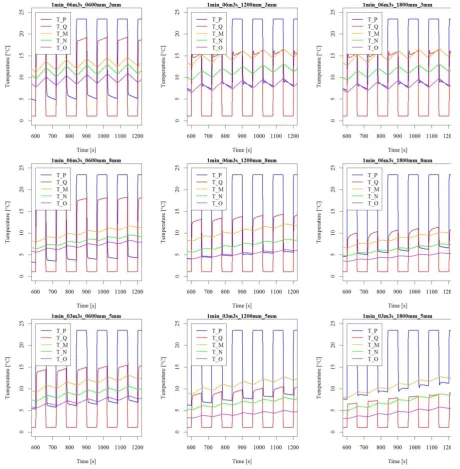
Figures 9, 10, 11 and 12 show the time dependency of
temperature and specific internal plate energy for all
plates together for 60 and 300 s reversing period,
respectively. Nine cases were selected to compare
influence of reversion period, air flowrate, length of the
plate and plate thickness. Specific internal plate energy is
related to the initial state, when the temperature of plates
is equal to the cold side temperature. It is important to
mention that the slope of this curve can be interpreted as
an intensity of heat transfer from/into plates. It can be
seen, that at approximately 1200 s there is no yet a fully
developed stationary periodical state. Temperature and
internal energy aren’t exactly the same in every time step. Figure 7One cycle of heating and cooling period for 3mm thick plates. A – end of cooling,
B – heating, C – end of heating, D – cooling, with sketch of evaluation points positions of discrete values M, N, O, P, Q.
May, 2015 Agric Eng Int: CIGR Journal Open access at http://www.cigrjournal.org Special issue 2015 87
88 May, 2015 CFD model of regenerative heat exchanger Special issue 2015
May, 2015 Agric Eng Int: CIGR Journal Open access at http://www.cigrjournal.org Special issue 2015 89
90 May, 2015 CFD model of regenerative heat exchanger Special issue 2015
All simulations were made up to the time 3000 s,
where the stationary periodicity was observed in all cases.
For the long plates, there is an effect of more uniform
temperature profiles at the hot side, because incoming air
has a longer time to be pre-heated and after flow
reversion. The shapes of plate’s specific energy
oscillations shows expected effect of more progressive
heat transfer in every cycle for thin plates. This is because
of the heat from the centre of thin plate is transferred
more rapidly, as is also seen at temperature profiles. It
can be seen, that the temperature difference between ends
of long plates is relatively higher, that on short plates, but
the difference isn’t dramatically considerable. It leads to
the recommendation, that for intensive heat regeneration
the long thin plates are better to use, than the short and
thick ones. It is clear, that in this case, the relatively
higher frequency of flow reversion is needed.
The shape of the temperature profile within the plate
is an important characteristic of the quality of the
heating/cooling process for the designed structure. It is
possible to obtain the time course of the temperature
profile for different sizes of plates using the unsteady
numerical simulation. Figure 13 shows a comparison of
May, 2015 Agric Eng Int: CIGR Journal Open access at http://www.cigrjournal.org Special issue 2015 91
1200mm and 2100 mm. The plate is placed in the axis of
the channel so that the distance from the edges of the
channel on both (hot and cold) sides of heat exchanger is
the same. The profile is evaluated in the longitudinal axis
of the channel, passing through the center plate
positioned closest to the centre of channel (in the case of
twenty plates thecentral axis of the plate number 10 is
analyzed).
92 May, 2015 CFD model of regenerative heat exchanger Special issue 2015
The graph shows the distance from the hot side on the
x-axis and the y value of the air temperature outside panel
and plate internal temperature inside the plate (in the
central part of the graph). Relatively fast change of
temperature of flowing air, and a slow change inside the
plateis seen when the direction of flow is changed. This
fact also corresponds to the temperature values at points
M, N and O in Figure 8.
At time 3480 there is a switch to the charging mode.
The warm air enters the heat exchanger and the internal
energy of plates increases. The flow direction in Figure
13leads from left to right. At the time of 3540 s the flow
is reversed and another 60s the heat exchanger is in a
state of discharge. The flow direction leads from right to
left. Interval from 3480 s to 3600 s corresponds to 120 s
period of this case. The shape of the temperature profile
inside the board has the stationary- periodic character. It
has only a very subtle deviation seen as an almost
invisible shift of profile curves upwardly and
downwardly during the heating and cooling.
The analysis presented here with 5mm thick plate
indicates that extension of boards can leads to increasing
the temperature difference between the hot and cold side
of the heat exchanger. It is also clear that in this reference
case is acceptable for all plate lengths, because there is no
effect of exhausting the heat capacity of plates – the
temperatures inside the plate do not approach the
temperature of the free air stream. This fact can be
interpreted, that the plates have sufficient heat capacity to
absorb the heat during the heating period.
4 Conclusions
The ANSYS/Fluent CFD software efficiently
simulated the thermal and flow conditions inside a plate
regenerative heat exchanger. Solved variants lead to the
deduction, that using relatively thin plates with higher
frequency of flow reversion is better for presented kind of
application because of more intensive heat transfer from
the whole plate mass. Also the relatively long plates can
be recommended due higher inlet air temperatures, which
are caused by longer air exposition to plates and also
larger heat transfer area. The absorbing theheat fromthe
airflow is the limiting factor forthe structure of theheat
exchanger.Such ability of plates depends
onsufficienttemperature gradientbetween the surface of
plate and theflowing air.CFDcan determine theheating
orcooling ofthe platewith respectthe structure of theheat
exchangerof this kind, so thatthere will not arise
excessiveheating of platesortheir insufficient warming.
There can be also done optimization for other design
parameters, such as thickness of plate, air stream
temperature, heating/cooling period or material properties
as requested.
5 Nomenclature
a, b, c [m] dimensions of channel for numerical
analysis
Bi [-] Biot number
cp [J/kgK] specific heat capacity
k [W/mK] thermal conductivity
lt,w,l [m] dimensions of one plate, indexes t –
thickness, w – width, l - length
te [K] cold side temperature
te’ [K] hot side temperature
ti [K] internal temperature
V [m3/s] volumetric flowrate
td,up,nd [K] plate temperature, indexes u – inside,
p – surface, n – cold side, d - hot side
[W/m2K] heat transfer coefficientAcknowledgements
The access to computing and storage facilities owned
by parties and projects contributing to the National Grid
Infrastructure Meta Centrum, provided under the
programme "Projects of Large Infrastructure for Research,
Development, and Innovations" (LM2010005) is highly
acknowledged.
May, 2015 Agric Eng Int: CIGR Journal Open access at http://www.cigrjournal.org Special issue 2015 93
Cafagni, A., D.Angeli, G.S. Barozzi, and S.Polidoro. 2013. A revised approach for one-dimensional time-dependent heat conduction in a slab. ASME Journal of Heat Transfer, 135: 031301-1 to 031301-8.
Kic, P., and G.A.K.Gurdil.1999. Trends in ventilation and air conditioning of animal houses. InProc. International conference Trends in agricultural engineering. 15-17 September, 389-393, CUA Prague.
Kic, P., and PPavlicek.2006 a. Heat regeneration in ventilation of animal houses.In Proc.17th Air-conditioning and
Ventilation Conference.2006. 17-19 May, 149-152, STP Praha.
Kic, P., andP.Pavlicek.2006b. The model of heat regenerator. In
Proc. The current problems in agriculture, food processing and waste management. 7-9 May, 47-50, SUA Nitra Kic, P., R. Chiumenti, S. Bortolussi, and F. da Borso. 2007.
Ventilation control of pig-houses during winter
period.InProc. 3rd IFAC Workshop on Mathematical and Control Applications in Agriculture and Horticulture. 28 September, 289-294, Pergamon Press, Hannover
Mladin, E., D. Stanciu, and J. Padet.2010. Transient thermal coupling for flows over a finite thickness plate exposed to a time-dependent temperature, InProceedings of the Roman Academy, Series A, 11(2): 163-170.
Pavlicek, P. 2007. Regenerative heat exchanger in ventilation of animal houses.Ph.D. diss., Czech University of Life Sciences, Prague
Willmott, A.J. 2011. Regenerative Heat Exchangers, Thermopedia: A-to-Z Guide to Thermodynamics, Heat andMass Transfer,
and Fluids Engineering, DOI: