Semi-Automatic 2D
to
3D Conversion Using
Low-Rank Matrix Recovery
https://doi.org/10.3991/ijoe.v14i01.7838
Hongxing Yuan
Ningbo University of Technology, Ningbo, China
Abstract—Semi-automatic 2D-to-3D conversion is a promising solution to 3D stereoscopic content creation. However, the depth continuous transition be-tween user marked neighboring regions will be lost when user scribbles are sparse. To help solve this problem, a piecewise-continuity regularized low-rank matrix recovery method is developed. Our approach is based on the fact that a depth-map can be decomposed into a low-rank matrix and an outlier term ma-trix. First, an initial dense depth-map is interpolated from the user scribbles us-ing mattus-ing Laplacian scheme under the assumption that depth-map is piece-wise-continuous. Second, a piecewise-continuity constrained low-rank recovery model is developed to remove outliers which are introduced by the interpola-tion. Experimental comparisons with existing algorithms show that our method demonstrates significant advantage over depth continuous transition between neighboring regions.
Keywords—2D-to-3D conversion, depth estimation, piecewise-continuity, low-rank, sparse interpolation
1
Introduction
With the development of 3D display technology, increasingly kinds of 3D electron-ic products, such as television, mobile phone, projector, are appearing in the ordinary people's life [1]. However, there is little 3D content to be played on these devices. Most videos and images are still in 2D. Thus, it is urgent need for 2Dto3D
conver-sion which can generate 3D content from existing 2D images/videos.
The main challenge of 2Dto3D conversion is how to retrieve the depth infor-mation from 2D images/videos which lost in the capture process. Existing 2Dto3D
Semi-automatic methods are possible to get higher quality depth-maps as they combine both depth cues and manual operations. Therefore, in recent years, many semi-automatic schemes have been proposed. However, if the user scribbles are sparse, existing methods are hard to capture the depth continuous change between neighboring regions, which will lead to visual fatigue. Surprisingly, there are few semi-automatic works addressing the issue.
We tackle the issue by formulating the depth estimation as a low-rank matrix re-covery problem. Our work is motivated by the recent matrix completion to the colori-zation problem [2]. Unfortunately, the method in [2] cannot be applied to depth esti-mation directly. An additional regularization term should be introduced to the method so as to improve the matrix completion accuracy. Since the color image can be con-verted to the monochrome image by a transform matrix, in [2], an extra regulation term can be added to the matrix completion using the relation. However, no transform matrix is available which converts the estimated depth-map to the input image. To fix the problem, we assume that two neighboring pixels should have similar depth if their colors are similar. We formalize this premise into a local depth consistency interpola-tion which is motivated by matting Laplacian method [3]. Then, we develop a discon-tinuity constrained low-rank matrix recovery approach to refine the interpolated re-sult.
Similar to StereoBrush [4], in our method, the user brushes sparse scribbles on an input color image where lighter intensities indicate closer from the camera and vice versa. By formulating our problem into a discontinuity constrained low-rank matrix recovery, depth transition between neighboring regions will be more continuous while preserving depth boundaries. In particular, the main contributions of our work are: ! To the best of our knowledge, our work is the first to formulate semi-automatic
2D-to-3D conversion as a low-rank matrix recovery problem. The low-rank matrix representation can refine depth-maps by removing the outlier term. This initializes to applying recent advances in low-rank methods to the 2D-to-3D conversion prob-lem.
! Low-rank matrix recovery can work when enough samples are available. Inspired by matting Laplacian method [3], we develop a local depth consistency interpola-tion method to provide the ample samples from the sparse user scribbles.
! We develop a quadratic cost regularized low-rank matrix recovery model to re-move depth outliers while preserving object boundaries.
2
Related works
In this section, only related semi-automatic 2D-to-3D conversion approaches are discussed. A more detailed review of related methods can be found in [6]. Wu et al. [7] use the interactive segmentation tool to extract the object from the background, and then the depth information is assigned to the segmented objects and the back-ground respectively. However, the interactive segmentation is cumbersome, and not easier than the manual 2D-to-3D conversion. To make the interactive segmentation easier, Aksoy et al. [8] over-segment image into regions with geometrical convexity and intensity homogeneity, and then the regions are merged with respect to the user scribbles, geometry and intensity constraints. Once segmentation is done, user is again required to mark strokes on the segmented objects indicating relative depth ordering. In [9], Guttmann et al. propose a segmentation like depth estimation method where each user label is not considered as a separate object but as a separate depth. User scribbles are marked on a few key frames to assign some desired depth values. Next, these scribbles are used to train the support vector machine (SVM) classifiers using the scale-invariant feature transform (SIFT) for each key frame. Then, those pixels with high confidence are tuned for the particular depth by the SVM classifier. Finally, a linear system is solved via least squares to get the rest of depth. The system combines the initial user constraints, spatial and time smoothness constraints. Solving of this system is equivalent to solving the random walks (RW) problem.
The issue with [9] is the computation complexity which requires SIFT feature ex-traction and SVM classifiers training to get the final depth-map. In [10], the SVM classifiers are removed and only user scribbles are used to generate the initial depth-map. The final depth-map is interpolated by the RW segmentation framework devel-oped by Grady [11]. The limitation with [10] is that the resulting depth-map object boundaries are lost due to the smoothing properties of RW. To solve the problem, in [12], Phan combines RW [11] and Graph Cuts (GC) [13] which utilizes both the smoothing properties of RW and the strong object boundaries provided by GC. The initial depth-map is generated by GC. Then, edges in RW are weighted by the initial depth-map. The combination cleans up object boundaries while maintaining smooth gradients in RW. However, when user scribbles are sparse, the combination cannot capture the continuous depth transition between neighboring regions. To improve depth quality at object boundaries, in [14], Yuan et al. incorporate nonlocal neighbors into the RW model.
intro-duced by matting Laplacian scheme. We notice that Lu et al. [18] also apply low-rank constraints on depth enhancement. The differences between our and their method are: (1) Lu et al. [18] assume RGB-D patches lie in a low-dimensional subspace and we apply low-rank regularization to the whole map; (2) the focus of [18] is depth-map completion and our problem is sparse-to-dense depth propagation in semi-automatic 2Dto3D conversion.
3
Problem formulation
First of all, we provide here some notations used throughout the paper. Scalars are non-bold, vectors are bold lowercase and matrices are bold capital. We assume that matrices are stored in column-major order and one-based indexing is used.
A
"
!
h w! means its row ish
, width isw
and all elements are real numbers. The (i, j)-th entry of a matrixA
is denoted byA
ij. Similarly,a
iis the i-th component of a vectora
. The conjugate transpose ofA
isA
! and similarly for vectors. The matrices trace isdenoted by Tr. The Frobenius norm of a matrix
A
is denoted byA
F, thel
0 norm by0
A
(i.e., a total number of non-zero elements inA
), thel
1 norm byA
1, and the standard inner product between two matricesA
andB
by A B, =Tr(A B! ) (2 ,
F=
A A A ). The shrinkage operator for a matrix A is defined as
{
}
( ) sgn( ) max ,0
S! A = A ! A"! where the (i, j)-th entry of sgn( )A is 1 if Aij!0,
oth-erwise is -1; the (i, j)-th entry of A"
!
is Aij"!;!
is the Hadamard product. The singular shrinkage operator for a matrixA
is denoted byD( ) max{ ,0} T! A U= " #! V whereU V! T=A.
c
P
is a reshape operator which converts a matrix to a column vec-tor, andP
c!1 is the inverse operator. For instance, if( )
c
P
=
a
A
wherea
!
!
N, h w!"
A
!
andN h w
=
!
, thenA
=
P
c!1( )
a
and( 1)j h i ij
a
! " +=
A
.Suppose that we are given a color image
I
"
!
h w! !3 and a partially user labeled imageS
"
!
h w! . The semi-automatic 2D-to-3D conversion problem is first to obtain a sparse initial depth-map h ws
"
!D
!
with user labeled imageS
, then to estimate a full depth-map h wf
"
!D
!
which best approximates the underlying true depth ofI
. This is an ill posed problem since we have no knowledge about the underlying true depth, and the evaluation of best approximation can be in many ways. To well define the problem, prior knowledge should be introduced. We consider the problem under two assumptions:Assumption 1. The depth-maps are piecewise-continuous.
Assumption 2. The depth-maps are low-rank.
fact that any image can be effectively approximated by a low-rank matrix plus a sparse matrix [19]. With Assumption 1, we obtain an initial estimated depth-map using local depth consistency interpolation which is motivated by the matting Lapla-cian method [3]. Then, a refined depth-map is extracted from the initial depth-map by formulating depth estimation as a low-rank matrix recovery problem with the As-sumption 2. Further, to thoroughly remove the texture details introduced by interpola-tion, we add a discontinuity constrained smooth regularization term to the low-rank method.
4
Method
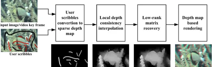
The workflow of the proposed method is showed in Fig.1. In our approach, the us-er masks on the input color image, genus-erating a scribbles map covus-ering on original image indicating the user desired depth. The masked intensity or color is lighter, the depth value is bigger. Then, we use image subtraction techniques to extract the sparse depth hypothesis. To get the initial dense depth-map, we apply matting Laplacian method [3] to perform sparse interpolation with the Assumption 1. The main idea of matting Laplacian scheme is that depth can be represented as a linear function of colors in a small window.
Fig. 1. The flowchart of the proposed method for semi-automatic 2D-to-3D conversion
constrained term. With help of the constrained term, the low-rank method can remove most texture details in interpolated depth-map while preserving object boundaries.
With the recovered depth from the input color image, we can now apply depth im-age based rendering (DIBR) to create a new view for 3D stereoscopic display. Ana-glyph image has been a popular representation for stereoscopic 3D. To generate ana-glyph image, the input image is given a red hue, and the image synthesized by DIBR is given a cyan hue. The anaglyph image is the combination of the two hue images.
4.1 Local depth consistency interpolation
In [20], Cand`es et al. shows the number of sampled entries must be bigger than a constant, then the low-rank matrix can be perfectly recovered with high probability. Thus, in [2], for each unlabeled pixel, monochrome intensity affinities are used to find all its neighboring labeled pixels, and then it is labeled with the weighted sum of the neighbors' labels. However, in 2D-to-3D conversion, user scribbles are sparse and separated. The simple neighboring labels propagation will not work in our case. To propagate the sparse user labels to the entire image, we assume that pixels with simi-lar colors should have roughly simisimi-lar depth. Namely, depth distributions are local consistency. The local depth consistency interpolation is motivated by the matting Laplacian method [3]. Its intuition is that depth can be represented as a linear function of image colors in a small window.
The depth interpolation problem is formulated as:
min{ ( ) ( )}
f
T T
f f +w f ! s "s f ! s
d d Ld d d d d (1)
Where the parameter
w
balances the relative influence between user scribbles and color similarity.d
s=
P
c( )
D
s where its i-th entry is set to user input depth if pixel i is at user labeled region, otherwise it is set to zero.d
f=
P
c( )
D
f . L is the N N! mat-ting Laplacian matrix, and !s is a N N! diagonal matrix whose (i, i)-th entry is 1 if pixel i is labeled by the user.To solve the problem (1), let its derivative w.r.t df be zero, and the following linear system equation is obtained:
(L+w!s)df =w!sds (2)
The optimal df can be obtained by solving (2) using the conjugate gradient algo-rithm. The final interpolated depth-map is obtained by 1( )
f =Pc! f D d .
4.2 Low-rank matrix recovery
0 ,
min{D E rank( )D +! E }, s.t. D E D+ = f (3)
The problem in (3) with rank and
l
0 norm minimization is NP-hard. In [18], Cand`es et al. prove that the nuclear norm minimization is the tightest convex relaxa-tion of the NP-hard rank minimizarelaxa-tion problem. In [21], Elad demonstrates thatl
0 norm minimization problem can be approximated by the convexl
1 norm minimiza-tion. Thus, the problem in (3) can be relaxed into the following problem:* 1
,
min{D E D +! E }, s.t. D E D+ = f ()
To preserve the depth discontinuity while removing texture details introduced by sparse interpolation, we add an extra regularization term to the low-rank matrix re-covery problem. By introducing the regularized term to low-rank method, Assump-tion 1 and AssumpAssump-tion 2 are used together. Thus, we formulate the problem in (4) to a more robust form as follows:
* 1
,
min{ ( ) }, s.t.
2 T Tx x x Ty y y f
! "
+ + # + # + =
D E D E d G G G G d D E D
(5)
Where
d
=
P
c( )
D
.G
x andG
y are N N! bi-diagonal matrices to represent gra-dient operator on N pixels along the horizontal and vertical directions, respectively. Thus, all the elements ofG
x andG
y are equal to 1 on the main diagonal, all the elements ofG
x are equal to -1 on the h-th diagonal below the main diagonal, all the elements ofG
y are equal to -1 on the first diagonal below the main diagonal, and all other elements ofG
x andG
y are equal to 0.!
xand!
y are N N! diagonal ma-trices to indicate the input image gradients magnitude along the horizontal and verti-cal directions, respectively. Namely, the (i, i)-th entry of!
x and!
y are functions of image gradients magnitude at pixel i along the horizontal and vertical directions, respectively.The regularization term in (5) comes from the Assumption 1. Since depth-maps are piecewise-continuous, the uniform color regions should have uniform depth values, and depth edges should coincide with their photometric edges. Because the magnitude of image gradient is smaller in uniform regions and larger around image edges, the depth is desired to be smooth in uniform regions, and be preserved around image edges. Formally, we formulate the piecewise-continuous cost term as follows:
2 2
( )
x(
)
y(
)
i x i i y i iWhere x 1 (1 x i) i
w e! "
= + I , y 1 (1 y i) i
w e!"
= + I . In other words, the magnitude of image gradient is larger, the weights x
i
w
and y iw are smaller. Therefore, we smooth depth in low gradient regions and preserve depth in high gradient regions by minimizingE( )D .
We can rewrite piecewise-continuous cost for all pixels i = 1, 2, ..., N of (6) in ma-trix form as:
( )
T(
T T) }
x x x y y yE
D d G
=
!
G G
+
!
G d
(7)Where
!
x( , )
i i
=
w
ix,!
y( , )
i i w
=
iy. E( )D is just the regularization term in (5).By introducing the piecewise-continuous regularization term to (4), we obtain a ro-bust low-rank matrix recovery formulation showed in (5) which can preserve depth discontinuity while removing texture details introduced by sparse interpolation. Thus, the depth refinement is converted to find the best solution of (5).
4.3 Optimization algorithm
We use the ALM algorithm [5] to solve the problem in (5). In order to solve (5) us-ing ALM, we introduce a slack vector
l
!
!
N to surrogated
. Thus, the term con-tainingD
and the term containingd
are decoupled. Then, the problem (5) is equiva-lently defined as follows:* 1
,
1
min{ ( ) },
2
s.t. , ( )
T T T
x x x y y y
f Pc
! "
#
+ + $ + $
+ = =
D E D E l G G G G l
D E D D l
(8)
Thus, the solution of problem (5)) is converted to solve (8). The Lagrangian func-tion of problem (8) is:
1 2 1 2 * 1
2
2 1 1
1 2 1 2 ( , , , , , , ) ( ) 2 , , ( ) ( ) 2 2
T T T
x x x y y y
f f F c c F
L
P P
!
µ µ
"
µ
#µ
#= + + $ + $
+ # # + # # + # + #
D E l Y Y D E l G G G G l
Y D D E D D E Y l D l D
(9)
The ALM algorithm solves problem (8) by choosing Y1, Y2, µ1 and µ2 judiciously and then minimizing L( , , , , , , )D E l Y Y1 2 µ µ1 2 as a function of D, E, l alternately. The results are used to choose a newY1, Y2, µ1 and µ2, and the procedure repeats until it converges.
5
Results and discussion
Ran-dom Walks (HGR) [12]. We also do experiments for our method with different regu-larized term's weight to see the regularization term's improvement to low-rank meth-od. The test images in [12] are used for comparison.
5.1 Comparisons with existing methods
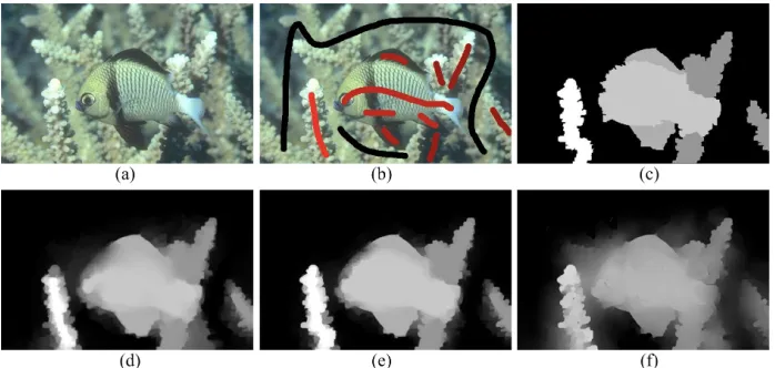
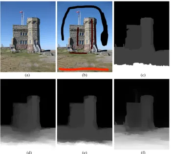
We first compare the proposed method and three leading algorithms for semi-automatic depth estimation. In Figs. 2-4, we have compared the depth estimation results for several test images. In each figure, panel (a) illustrates the input color im-age, panel (b) shows the user marked scribbles overlaid on the original imim-age, panel (c) is the depth-map generated by GC [12], panel (d) is the result done by RW [10], panel (e) is the depth from HGR [12], panel (f) shows depth generated by our ap-proach. For Figs. 2-4, we both set
!
=10, !=100.As shown in Fig.2, the depth from our method captures the continuous changes of the scene. We can feel the gradual depth transition inside the fish and reeds of our result. However, the depth variation of the left marked reed is lost in results of RW [10], GC [12], and HGR [12]. The continuous depth transition in the region of the fish's head is also lost in these methods. With our approach, we can experience more depth transition between object boundaries in Fig.2.
As shown in Fig.3, with RW [10], GC [12], and HGR [12], the bottom left corner and bottom right corner of the depth-map are over-light making the changes between these regions and their neighboring regions abrupt. Moreover, the depth discontinuous changes between two men are lost with hybrid Graph Cuts and Random Walks. The depth transition of those regions are more continuous of our method. The two men's boundaries of our method in Fig.3 are more recognizable than the three approaches.
Fig. 3. Performance comparison for Naruto image. (a) Input color image. (b) User labeled image. (c) Depth from GC. (d) Depth from RW. (e) Depth from HGR. (f) Depth from the proposed.
As shown in Fig.4, on the grass there are only two user scribbles. This scenario makes the depth-map of RW [10], GC [12], and HGR [12] change abruptly from bottom to up on the grass. In our result, the depth changes are gradual. Besides, the tower boundaries of our approach are clearly demonstrated. The RW [10] and HGR [12] are failed to recovery the depth of small structures of the tower, e.g. the pillars on the left ground level of Fig. 4(d) and 4(e) are lost.
5.2 Improvement of low-rank method by regularization
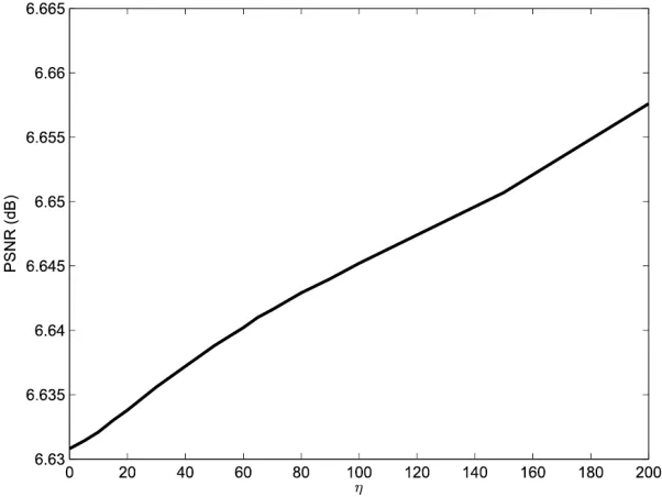
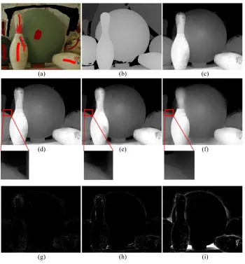
The “Bowling” image taken from the Middlebury stereo evaluation database is used to evaluate regularized term's improvement to low-rank method. Since the ground truth depth of “Bowling” image is available, the PSNR is used to measure the improvement from the regularized term. We set
!
=10, and increase!
from 0 to 200gradually. As shown in Fig.5, The PSNR rose along with regularized term's weight
!
. Although the PSNR will be improved as!
be increased, the object boundaries also begin to be blurred. Fig.6 shows examples of recovered depth with different weight!
setting. From Fig.6, we notice that the object boundaries inside the red box are blurred when!
=1000
. In order to see the differences clearly, in Fig.6, the outlier termE with different weight
!
is scaled 5 times. The outlier terms in Fig.6 show that more and more details are removed from the initial estimated depth along with increasing!
. In experiments, we find
!
=100 is a proper choice that trades off the objectbounda-ries versus the depth uniformity.
Fig. 6. The recovered depth with different
!
. (a) User labeled image. (b) Depth of ground truth. (c) Depth recovered with!
=0. (d)Depth recovered with!
=100. (e)Depth re-covered with!
=500. (f)Depth recovered with!
=1000. (g) Outlier term E with=0
!
. (h) Outlier term E with!
=100. (i) Outlier term E with!
=1000.Table 1 shows the PSNR of RW [10], GC [12], and HGR [12]. Fig.5 and Table 1 illustrate that even without regularized term, our method improves the PSNR by more than 1 dB compared with RW [10], GC [12], and HGR [12].
Table 1. PSNR of Bowling image (dB)
RW GC HGR
5.3 Discussion
In semi-automatic 2D-to-3D conversion, when user scribbles are sparse, how to make depth transition between user marked regions be continuous is a challenge. Zhuo has proved that matting Laplacian based sparse interpolation can capture the continuous changes of the depth-map [15]. But the issue with matting Laplacian in-terpolation is that texture details from input color image will be introduced to the depth-map. We argue that the discontinuity preserving smooth constrained low-rank method offers one promising approach to remove the texture information introduced by the interpolation.
The weakness of our method is that the depth of a sub-region beside an object is lower than the depth of neighboring regions when its color is darker than the color of neighboring regions. For example, on the right side of Fig. 3(f), the depth of the dog's neck is lower than the neighboring regions. This is because the matting Laplacian sparse interpolation is based on the assumption that depth is a linear function of image colors in a small window. In the input color image, the color of this region is darker than the other parts of the dog. This region is too large to be corrected by the low-rank method. Maybe single-view depth cues can be introduce to fix the issue.
6
Conclusion
The study focuses on continuous depth transition of semi-automatic 2D-to-3D con-version when user scribbles are sparse. Based on the view that depth is piece-continuous, we obtain the initial dense depth-map from user scribbles by matting Laplacian sparse interpolation. By treating the depth-map refinement as a low-rank matrix recovery problem, we develop a discontinuity preserving smooth regularized low-rank method to remove texture details which is introduced by sparse interpola-tion. The experimental results have demonstrated that the depth transition between sparse marked regions of our method is more continuous in comparison with existing state-of-art method.
To the best of our knowledge, this is the first time that low-rank method is used for 2D-to-3D conversion. There are several ways to improve the method. Since the initial samples is vital for low-rank matrix recovery, we can make use of existing kinds of depth cues to refine the sparse interpolated result. Other regularization terms can also be incorporated into low-rank method with the same way. Moreover, we can intro-duce an error term to make the low-rank method be more robust to outliers.
7
Acknowledgment
8
References
[1]R. Marcelino, J.B. Silva, V. Gruber and M.S. Bilessimo, “Immersive learning environment using 3d virtual worlds and integrated remote experimentation,” International Journal of Online Engineering, vol. 9, pp. 31-34, 2013. https://doi.org/10.3991/ijoe.v9iS1.2353 [2]S. Wang and Z. Zhang, “Colorization by matrix completion,” The 26th AAAI Conference
on Artificial Intelligence, pp. 1169–1175, 2013. https://doi.org/10.1145/1186562.1015780 [3]A. Levin, D. Lischinski and Y. Weiss, “A closed-form solution to natural image matting,”
IEEE Transactions on Pattern Analysis and Machine Intelligence, vol. 30, no. 2, pp. 228– 242, 2008. https://doi.org/10.1109/TPAMI.2007.1177
[4]O. Wang, M. Lang, M. Frei and et al., “StereoBrush: interactive 2D to 3D conversion us-ing discontinuous warps,” The 8th Eurographics Symposium on Sketch-Based Interfaces and Modeling, pp. 47–54, 2011. https://doi.org/10.1145/2021164.2021173
[5]Z. Lin, M. Chen, L. Wu and et al., “The augmented Lagrange multiplier method for exact recovery of corrupted low-rank matrices,” Tech. Rep. UILU-ENG-09-2215, UIUC, 2010. https://arxiv.org/abs/1009.5055
[6]X. Cao, A. Bovik , Y. Wang et al., “Converting 2D video to 3D: an efficient path to a
3D experience,” IEEE Transactions on Multimedia, vol. 18, no. 4, pp. 12–17, 2011. https://doi.org/10.1109/MMUL.2011.65
[7]C. Wu, G. Er, X. Xie and et al., “A novel method for semi-automatic 2D to 3D video con-version,” IEEE 3DTV Conference, pp. 65–68, 2008. https://doi.org/10.1109/ICASSP .2012.6288159
[8]Y. Aksoy, O. Sener, A. Alatan and et al., “Interactive 2D-3D image conversion for mobile devices,” IEEE 19th International Conference on Image Processing, pp. 2729–2732, 2012. https://doi.org/10.1109/ICIP.2012.6467463
[9]M. Guttmann, L. Wolf and D. Cohen-Or, “Semi-automatic stereo extraction from video footage,” IEEE 12th International Conference on Computer Vision, pp. 136–142, 2009. https://doi.org/10.1109/ICCV.2009.5459158
[10]R. Rzeszutek, R. Phan and D. Androutsos, “Semi-automatic synthetic depth map genera-tion for video using random walks,” IEEE International Conference on Multimedia and Expo, pp. 1–6, 2011. https://doi.org/10.1109/ICME.2011.6011898
[11]L. Grady, “Random walks for image segmentation,” IEEE Transactions on Pattern Analy-sis and Machine Intelligence, vol. 28, no. 11, pp. 1768–1783, 2006. https://doi.org/10.1109/TPAMI.2006.233
[12]R. Phan and D. Androutsos, “Robust semi-automatic depth map generation in uncon-strained images and video sequences for 2D to stereoscopic 3D conversion,” IEEE Trans-actions on Multimedia, vol. 16, no. 1, pp. 122–136, 2014. https://doi.org/10.1109/TMM. 2013.2283451
[13]Y. Boykov and G. Funka-Lea, “Graph cuts and efficient N-D image segmentation,” Inter-national Journal of Computer Vision, vol. 70, no. 2, pp. 109–131, 2006. https://doi.org/10.1007/s11263-006-7934-5
[14]H. Yuan, S. Wu, P. Cheng and et al. “Nonlocal random walks algorithm for semiautomatic 2D-to-3D image conversion,” IEEE Signal Processing Letters, vol. 22, no. 3, pp. 371–374, 2015. https://doi.org/10.1109/LSP.2014.2359643
[15]S. Zhuo and T. Sim, “Defocus map estimation from a single image,” Pattern Recognition, vol. 44, no. 9, pp. 1852–1858, 2011. https://doi.org/10.1016/j.patcog.2011.03.009
[17]X. Liang, X. Ren, Z. Zhang and et al., “Repairing sparse low-rank texture,” The 12th Eu-ropean Conference on Computer Vision, pp. 482–495, 2012. https://doi.org/10.1007/978-3-642-33715-4_35
[18]S. Lu, X. Ren and F. Liu, “Depth Enhancement via Low-Rank Matrix Completion,” IEEE Conference on Computer Vision and Pattern Recognition, pp. 3390–3397, 2014. https://doi.org/10.1109/CVPR.2014.433
[19]C. Leng, J. Xiao, M. Li and et al., “Robust adaptive principal component analysis based on intergraph matrix for medical image registration,” Computational Intelligence and Neuro-science, Article ID 829528, 2015. http://dx.doi.org/10.1155/2015/829528
[20]E. Cand‘es and B. Recht, “Exact matrix completion via convex optimization,” Communi-cations of the ACM, vol. 55, no. 6, pp. 111–119, 2012. https://doi.org/10.1007/s10208-009-9045-5
[21]M. Elad, “Sparse and redundant representations from theory to applications in signal and image processing,” New York: Springer Press, pp. 17–30, 2010. https://doi.org/10.1007/ 978-1-4419-7011-4
[22]E. Hale, W. Yin and Y. Zhang, “Fixed-point continuation for l1-minimization: methodolo-gy and convergence,” SIAM Journal on Optimization, vol. 19, pp. 1107–1130, 2008. https://doi.org/10.1137/070698920
[23]J. Cai, E. Cand‘es and Z. Shen, “A singular value thresholding algorithm for matrix com-pletion,” SIAM Journal on Optimization, vol. 20, pp. 1956–1982, 2010. https://doi.org/10.1137/080738970
9
Author
Yuan Hongxing is an associate professor in School of Electronics and Information
Engineering, Ningbo University of Technology, China. His research interests include 3D video processing, 2D-to-3D conversion. (E-mail:[email protected])