Design of an Automatic Collision Avoidance System for
Ships Based on Wireless Sensor Network
https://doi.org/10.3991/ijoe.v14i05.8639
Haohao Yuan
Guangxi University of Science and Technology, Liuzhou, China [email protected]
Abstract—The system designed is a ship collision avoidance system based on consistent use of satellite positioning technology, spread spectrum commu-nication technology and a wireless sensor network. The system design includes: an information collecting terminal, a data processing terminal and a mobile data terminal as the three main parts.CC2530 is selected as the master chip for the information collecting terminal, and the GPS module with NEO-6M UBLOX satellite positioning function is used to obtain the latitude, longitude, heading and other information. The AS62-T30 wireless communication module is used to realize the data interaction between ships, and a 0.96-inch OLED display module is used to show the current location of the ship, thus realizing the GPS positioning data receiving, data analysis, information display, data integration and transmission, and other functions. In terms of the software in the data pro-cessing terminal, QT5 is selected as the development environment, and QtSql as the database to process and store the data packet sent by the information collect-ing terminal. The system has many functions includcollect-ing real-time data analysis and alarm, real-time location annotation, track query, route planning and weath-er forecasting, etc.
Keywords—collision avoidance, wireless communication, wireless sensor net-work
1
Introduction
Water transport has traditionally been a high-risk industry. According to statistics, there are about 200 wrecked ships each year, of which 43% are due to collision acci-dents [1]. Despite the continuous improvement of the navigation technology and the development of the transport industry is developing, the increasing number of ships has led to higher sailing density and worse navigational environment. Moreover, as the ships are becoming bigger in size, more specialized, and faster in speed, the risk of ship accidents is hard to reduce, and as a result, water traffic accidents are still in a severe situation.
which are capable of dynamically combining the ship’s position, speed and course with its static data such as ship name, call sign, draft and dangerous goods, and broadcasting this information via VHF to the ships and shore stations in nearby waters so that the adjacent ships and shore stations can learn about the dynamic and static information of all nearby ships in the sea in a timely manner, and can immediately call each other to coordinate and take collision avoidance actions. However, since AIS uses radar signals to detect the positions of obstacles, the accuracy is not high and the network flexibility is low, which cannot satisfy the safety requirements of modern navigation any longer [2-3].
A wireless sensor network (WSN) consists of a series of sensors with wireless communication functions. Sensors attached to physical vessels not only have the function of collecting position information, but also can form a wireless communica-tion network for efficient data transmission [4-5]. This paper, by combining the AIS automatic identification system and the information transmission capability of WSN, designs a ship collision avoidance system to solve such problems as the low accuracy of pure AIS navigation, and the poor communications caused by inadequate network coverage.
2
System structure
MCU Controler
Displayer module Wireless
GPS
Wireless
module
Application program
Data Processing Power
Mobile
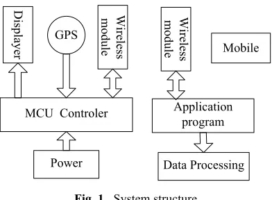
Fig. 1. System structure
When every ship is equipped with this system, the ships will be able to carry out long-distance communications through the wireless transceiver module. When the system is operating, the wireless transceiver module continuously sends information about the current ship’s position, name, number, heading and other information to other ships within the range of communication; at the same time, it receives the data packets sent by other ships in the communication range and analyzes the latitude and longitude, and then calculates the distance between the two ships. When the distance is less than the safety distance, an alarm will be sent out. The information collecting terminal and the data processing terminal are connected in a wireless way. The infor-mation collecting terminal collects inforinfor-mation and location of the ship and sends this information together with the information and locations of the other ships to the data processing terminal for processing. The mobile data terminal can be implemented with the GPRS data service of the mobile phone. In this way, the ship can obtain the weather forecast and related notices and information sent by the server, which will play a supporting role in maintaining the navigation safety of the ship.
3
Hardware design
Hardware design is mainly the design of the information collecting terminal. It takes the CC2530 controller as the processing unit, and expands the GPS module and wireless transceiver module. The ship nodes communicate through a fixed protocol by the wireless transceiver module. The GPS module locates the longitude and latitude of the ship where the node is located and displays the information on the LCD display. The information collecting terminal sends the position and information of this ship and others to the data processing terminal through the wireless module.
3.1 Processor
RemoTI’s ZigBee RF4CE, and it is the first ZigBee RF4CE compliant protocol stack in the industry, allowing wireless download and supporting system programming. In addition, CC2530 incorporates an 8kB RAM, with up to 256KB flash memory and other powerful supporting functions and peripherals, includeing 2 USARTs, 12-bit ADCs and 21 generic GPIOs [6-7]. In the system, the ZigBee module is mainly used for node sensing information collection, data transmission and GPS positioning data processing.
3.2 GPS positioning module
The system uses a GPS satellite positioning module with the NEO-6M as the core chip [8-9]. This module, with high performance and low power consumption, is a satellite positioning receiver, with full-features. The module uses a UART communication interface to communicate directly with the CC2530 processor.
3.3 Sensor
We use an extended temperature sensor for the detection of the navigation water temperature, which is an 18B20 digital temperature sensor probe. It is single-bus structured. After a normal startup, it can serially output the current temperature with an accuracy of 0.50oC. The main control chip drives it and reads the data by generat-ing the timgenerat-ing sequence to stimulate the sgenerat-ingle-bus drivgenerat-ing.
3.4 Wireless transceiver interface
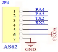
The system wireless transceiver module uses the AS62-T30, which is an industrial-grade wireless data transmission module with a transmission power of 1W and high stability. The module uses the SX1278 main chip, LORA spread spectrum transmis-sion and TTL level output, and is compatible with 3.3V and 5V I/O port voltages. A highly efficient circular intersectional error correction coding algorithm is used. With high coding efficiency and strong error correction ability, in case of sudden interfer-ences, it can actively correct the interfered data packets, with a maximum continuous error correction of 64bit and a strong resistance to interference ability, and the trans-mission distance can be up to 7000 meters.
The module has four operating modes, set by pins 1 and 2. The design in this paper uses mode 0. The operating frequency of AS62-T30 ranges between 410MHz~441MHz, with a total of 32 channels and channel spacing of 1M. Parame-ters like the serial port baud rate, sending and receiving frequencies, transmission power and radio frequency rate can be modified online. The wireless transceiver module pins 3 and 4 and the CC2530 serial port are cross-connected to achieve data sending and receiving. The interface is shown in Fig. 2.
3.5 Displayer module
The design in this paper uses an OLED12864 liquid crystal displayer to achieve the hardware platform data display. Although the OLED is small in size, it has very pow-erful display functions - it can display information by page or line, in the form of numbers, letters and Chinese characters etc., which are quite clear. In addition, the interface of the display module is simple and is connected with CC2530 in the serial IIC bus format.
4
Software design
4.1 Software design for the information collecting terminal
Y
N
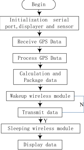
The development platform for the information collecting terminal processor is IAR 7.3, which is a piece of software specially designed for embedded development. The development environment includes an assembler, a C/C++ compiler, a linker, a file manager, a project manager and a C-SPY debugger. It supports at least 35 kinds of 8-bit, 16-bit and 32-bit microprocessors. The main functions include GPS data acquisi-tion and analysis, sensor data reading, ship posiacquisi-tioning and data transmission. The program flow is shown in Fig. 3.
After normal operation, the GPS module will output data packets containing longi-tude, latilongi-tude, speed, heading and other information in a fixed format. When the pro-cessor receives the latitude and longitude information of other ships, it calculates the distances between other ships and itself. Suppose the earth is a perfect sphere, then its average radius is 6371.004 kilometers, denoted as R. If we take the Longitude Zero as the baseline, then the distance between any two points on the earth’s surface can be calculated according to the latitude and longitude. Let the latitude and longitude of the first point A be (LonA, LatA) and those of the second point B be (LonB, LatB). Based on the baseline Longitude Zero, the east longitude is a positive value (Longitude), the west longitude is a negative value (-Longitude), the north latitude is 90-latitude (90-latitude), and the south latitude is 90+latitude (90+(90-latitude), and then after the above mentioned processing, the two points are counted as (MLonA, MLatA) and (MLonB, MLatB). Then according to the triangular derivation, we can get the formula for cal-culating the distance between the two points:
Included angle:
! ! !"# !"#$% ! !"# !"#$% ! !"# !"#$% ! !"#$% ! !"# !"#$% !
!"# !"#$% (1)
Distance between the two points:
!"#$%&'( !! ! !"##$% ! ! !"!!"# (2)
4.2 Agreement design
The information collecting terminal and the data processing terminal transmit data packets in a fixed format - S # Call sign # Ship name # Type # Contact # Draft # Length Width # Longitude # Latitude # Speed # Course angle # E. S represents the beginning of the data packet, and E, the end of the data packet. Each message is sepa-rated by the symbol #. The data collecting terminal constantly sends the information of the current ship and surrounding ships to the information processing terminal at an interval of 1s.
4.3 Data processing terminal software design
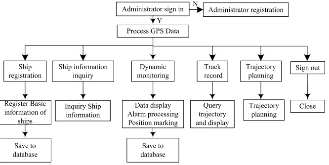
each interface. The main idea of the program design is: first, to create a database table for the project codes of the main functions, for the purpose of information registration and dynamic data recording and querying; second, to implement the administrator login page; third, to implement the administrator registration interface; fourth, to implement the function selection menu interface; fifth, to design each function inter-face according to the function requirements. The design flow chart of the program is shown in Fig. 4.
Administrator sign in
Process GPS Data
Administrator registration Y
N
Ship
registration Ship information inquiry monitoringDynamic recordTrack Trajectory planning Sign out
Register Basic information of
ships
Inquiry Ship
information Alarm processingData display Position marking
Query trajectory and display
Trajectory
planning Close
Save to
database databaseSave to
Fig. 4. Application program flow chart
Ship registration: the basic information of the ship is recorded into the database ta-ble, including: call sign, ship name, type, contact, draft, length and width. Implemen-tation process: enter the corresponding information in each input field, and when pressing the confirm button, check whether the input information meets the require-ments; insert the record into the information table to complete the registration, or ask the users to re-register.
Registration query: the query is implemented mainly by reading the registration da-ta da-table, and then displaying the information. In the design, we use the QTableWidget control to display in the form of tables. QTableWidget is a commonly used data table display control in the QT program, which uses a standard data model and whose cell data is constructed by the object of QTableWidgetItem, so we only need to fill out the information in each cell. In the table, each cell is expressed by the QTableWidgetItem control, and the whole table needs to be constructed cell by cell.
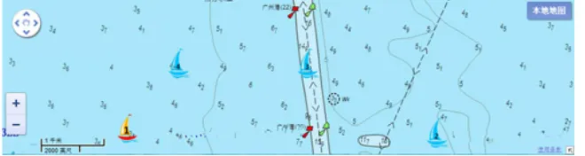
necessary to determine whether these are the data of the current ship or not. If they are, they will be saved in the data record table; and if they are the data of other ships, then the distances between the other ships and the current ship need to be calculated. The calculation method is shown in formula 4.1. Then, the set distance is compared with the calculated distance. If the distance is less than the set one, an alarm will be generated. Position displaying part: the ship’s information is displayed in the form of table using the QTableWidget control. The position display is achieved via three steps: preparing a nautical chart; loading a nautical chart; and marking the position. Step 1: download chart tiles and convert them to the Google tile format. Because Google Maps provides JavaScript version of the API, the system is based on JavaS-cript API programming interface design, and the main features include: positioning, zooming, map type switching and translation, etc.; Step 2: load the nautical chart, and use the Webkit-based QWebView browser controls to view and edit web pages dis-playing the nautical chart; Step3, the annotation process is to achieve communication between QT and html, and the operation of web pages. The first is to write the corre-sponding API interface in the html file, and then Qt will call the JavaScript function to pass longitude and latitude parameters. The implementation results are shown in Fig. 5.
Fig. 5. Monitoring interface
Track record: it consists of record data displaying, nautical chart track displaying, and position displaying. The record data displaying part reads the data record table and then displays the same as the table in the registration inquiry shows according to the selected date. The nautical chart displaying part is similar to the design of the position displaying part in the dynamic monitoring module, except that it needs to connect each marking point to achieve track displaying. The connection of the mark-ing points was achieved through the API interface, and the effect is shown in Fig.6.
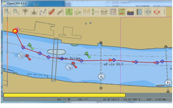
Route Planning: in the design, there are no known coordinate points in the route planning, so route planning and tracking can be difficult to achieve with this offline electronic nautical chart. Through investigation, it is found that OpenCPN is a practi-cal navigation application software system, which uses the wxWidgets interface framework, and supports OpenGL. It can operate on different platforms like Win-dows, Linux, and Mac systems. OpenCPN is a free software program that complies with the open source GPLv2 protocol and supports nautical charts in the S57 vector format and BSBv3 grid format. It also supports the S52 display standard, automatic nautical chart tracking and route planning and tracking. The software is added to the system application software, and through the virtual serial port, it establishes data communications and achieves route planning. The results are shown in Fig. 7.
Fig. 7. Route planning
4.4 Mobile data terminal
5
Testing
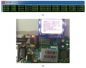
Data collecting terminal testing: the data collecting terminal hardware system and the PC are connected through the wireless transceiver module AS62-T30. The serial port assistant is installed on the PC terminal. When the distance between the two is 500m, 1000m and 2000m, the PC terminal can receive data packets in the following format: S # Call sign # Ship name # Type # Contact # Draft # Length Width # Longi-tude # LatiLongi-tude # Speed # Course Angle #E, as shown in Fig. 8a. The display on the collecting terminal can display the current position information and the current navi-gation water temperature in real time, as shown in Fig. 8b. This point-to-point exper-iment shows that the data collecting terminal and the wireless transceiver module can work properly.
a)
b)
Fig. 8. a Wireless transceiver module testing b Information collecting terminal testing
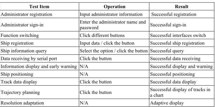
Data processing terminal testing: the data processing software is designed accord-ing to the function module, mainly includaccord-ing user management, ship registration, registration information inquiry, real-time monitoring, track record and inquiry, route planning. The tested part needs to cooperate with the hardware. See Table 1.
infor-mation. The weather data needs to be obtained online. Therefore, the mobile data terminal is used as the network hot spot. The specific interface of weather forecast is shown in Fig. 9.
Fig. 9. Mobile data terminal obtains weather information
Table 1. System test
Test Item Operation Result
Administrator registration Input administrator information Successful registration Administrator sign-in Enter the administrator name and password Successful sign-in Function switching Click different buttons Successful interfaces switch Ship registration Input data / click the button Successful ship registration Ship information query Select the option / click the button Successful query Data receiving by serial port Click the button Successful data receiving Information display and early warning N/A Successful display and warning Ship positioning N/A Successful positioning Track data display Click the button Successful data display Trajectory planning Click the button Successful display of tracks in a chart Resolution adaptation N/A Adaptive display
monitoring, track recording and route planning. The test contents and results are shown in Table 1.
6
Acknowledgements
This work was supported by the Natural Science Foundation of Guangxi (2016GXNSFBA380081), the Research Foundation of Education Bureau of Guangxi (KY2016YB249), the Research Foundation of Science and Technology Department of Guangxi(2015AC09004)
7
References
[1]Itoh. H.V., Yukimachi In.T. (2004), Human factors for human error prevention. Techno system, Tokyo.
[2]International Maritime Organization (2009), United Nations. Automatic Identification Sys-tem. Available Online: http://www.imo.org/includes/blastDataOnly.asp/data_id% D6645/227.pdf.
[3]IALA-2001, Guidelines on The Universal Automatic Identification System (AIS) Volume 1 Part I - Operational Issues Edition 1.1 [S]. Paris: IALA.
[4]Rabab, J.M., Woods, j., Mohammed, Q.S. (2015). (AMDC) Algorithm for wireless sensor networks in the marine environment (IJACSA). International Journal of Advanced Com-puter Science and Applications, 6(6), 218-223.
[5]Zhang, Y., Zhang, F. (2014). Research on the smart wireless sensor perception system and its application based on internet of things. Computer Modelling and New Technologies, 18(1), 44-51.
[6]Xin, Z., Chen, G, Li, X., Hu, L., Yuan, J., Gu, H., Cao P. (2013). Research on the zigbee network and equipment design based on the cc2530. Sensors & Transducers, 158(11): 89-94.
[7]Xin, Z., Hu, L., Chen, G., Song, Q., Li, H. (2014). The GPS information acquisition sys-tem based on Zigbee. Computer modelling & new technologies, 18(12B), 391-397. [8]Thrivikrama, Ashok, V.G., Srinivas, A. (2011). A novel two-stage self-correcting
GPS-free localization algorithm for GSM mobiles. Proceedings of the IEEE International Con-ference on Advanced Networks and Telecommunication Systems, 1-6. https://doi.org/10.1109/ANTS.2011.6163634
[9]Zhang, F., Wu, X., Zhang, S. (2013). GPS Location Accuracy Improvement By Wlan. Computer Modelling and New Technologies, 17(4), 224-228.
8
Author
Haohao Yuan is a Ph. D. student in Wuhan University of Technology and
cur-rently works for Guangxi University of Science and Technology, Liuzhou, 545006, China.