13 *Corresponding author
Email address: afereidoon@semnan.ac.ir
Study on buckling of steel cylindrical shells with an elliptical cutout
under combined loading
Abdolhossein Fereidoona,*, Kamal Kolasangianib, Amin Akbarpourc and Mahmoud Shariatid
a
Faculty of Mechanical Engineering, Semnan University, Semnan, Iran
b
Department of Mechanical Engineering, Shahrood University of Technology, Shahrood, Iran
c
Department of Mechanical Engineering, Semnan Branch, Islamic Azad University, Semnan, Iran
d
Department of Mechanical Engineering, Ferdowsi University of Mashhad, Mashhad, Iran
Article info: Abstract
In this paper, simulation and analysis of thin steel cylindrical shells with elliptical cutouts under oblique loading were studied using finite element method. First, the numerical results were validated by the results of experimental test performed by an INSTRON 8802 servo hydraulic machine. Also, the effect of cutout angle (θ), cutout size, cutout position (L0/L) and cutout aspect ratios (b/a) were investigated, where parameter (a) shows size of the cutout along longitudinal axis of the cylinder, parameter (b) is size of the cutout in circumferential direction of the cylinder on the buckling and post-buckling behavior of cylindrical shells with finite element method. It can be concluded that increasing width of the cutout extremely decreased the buckling load while the cutout height was constant. Moreover, changing position of the cutout from the mid-height of the shell toward the edges increased the buckling load.
Received: 25/05/2012 Accepted: 17/03/2013 Online: 11/09/2013
Keywords: buckling, cutout,
combined loading.
1. Introduction
Effect of cutouts on load-bearing capacity and buckling behavior of cylindrical shells is an essential consideration in their design. Cylindrical shells are frequently used for manufacturing aircrafts, missiles, boilers, pipelines, automobiles and some submarine structures. These structures may experience different types of compression loads in their longevity and yield buckling. Furthermore, these structures usually have disruptions, such as cutouts, which may have adverse effects on their stability.
Shu [1] and Robert and Rahman [2] investigated the limit load of cylindrical shells with circumferential cracks. Yun-Jae and Do-Jun [3] provided approximate J estimates for off-centered circumferential through wall cracks in cylinders under bending.
Meng-kao et al. [4] investigated buckling behavior of an elasto-plastic cylindrical shell with a cutout. Rahimi and Poursaeeidi [5] performed a parametric study on plastic strength of cylindrical shells with cutout under bending moment and axial loading.
JCARME Abdolhossein Fereidoon, et al. Vol. 3, No. 1, Autumn 2013
14
cylindrical shells subjected to internal pressure and axial compression loads using Abaqus. She studied influences of size and orientation of cutouts on buckling capacity. Also, Tafreshi and Colin [7] performed a numerical study using non-linear finite element analysis to investigate response of composite cylindrical shells subjected to combined load, in which post buckling analysis of cylinders with geometric imperfections is carried out to study the effect of imperfection amplitude on critical buckling load. Poursaeidi et al. [8] considered an elastoplastic material and used ABAQUS Software to analyze plastic behavior of cylindrical shells with circular or rectangular cutouts under pure bending. The shell had a circular cross section and both ends were clamped. The influence of size, location and number of the cutouts on the limiting bending moment of a cylindrical shell was also presented. Vartdal et al. [9] studied simply supported steel tubes with rectangular cutouts of different sizes positioned at their mid-length subjected to axial compression to assess effect of cutouts on the deformation behavior. Han et al. [10] studied effect of dimension and position of square-shaped cutouts in thin and moderately thick-walled cylindrical shells of various lengths by nonlinear numerical methods in ANSYS software. They also compared their results with experimental studies moderately thick-walled shells and ,finally, developed several parametric relationships based on analytical and experimental results using least squares regression method. Shariati and Mahdizadeh [11] studied effect of position of elliptical cutouts with identical dimensions on buckling and post-buckling behaviors of cylindrical shells with different diameters and lengths and developed several parametric relationships based on the numerical and experimental results using the Lagrangian polynomial method. Also, Shariati and Mahdizadeh [12] performed a similar numerical study using ABAQUS software to investigate response of steel cylindrical shells with different lengths and diameters, including elliptical cutout subjected to bending moment. They presented some relations for finding buckling moment of these structures.
15 In this paper, linear and nonlinear analyses were
carried out using the ABAQUS finite element software in order to study effect of the elliptical cutouts with identical dimensions on buckling and post-buckling behaviors of stainless steel 316ti cylindrical shells. Additionally, for several specimens, the experimental buckling test was performed using an INSTRON 8802 servo hydraulic machine and the results of experimental tests were compared to the numerical ones. A very good correlation was observed between experiments and numerical simulations.
2. Numerical analysis using the finite element method
The numerical simulations were carried out using general finite element program ABAQUS 6.10.1.
2.1. Geometry and mechanical properties of the shells
For this study, stainless steel 316ti thin-walled cylindrical shells were analyzed. An elliptical geometry was selected for cutout that was created in the specimens.
Furthermore, thickness of the shells was t=1 mm. Figure 1 shows geometry of the elliptical cutouts. According to this figure, parameter (a) shows size of the cutout along the
longitudinal axis of the cylinder and parameter (b) is size of the cutout in circumferential direction of the cylinder. The distance between center of the cutout and lower edge of the shell was designated by L0, as shown in Fig. 1. The specimens were nominated as follows: D42-L150-L075-a×b; the numbers following D and L show diameter and length of the specimens, respectively.
The cylindrical shells used for this study were made of stainless steel 316ti. The mechanical properties of this steel alloy were determined according to ASTM A370-05 standard [19], using the INSTRON 8802 servo hydraulic machine.
Stress–plastic strain curve and respective values are shown in Fig. 2. Based on the linear portion of stress–strain curve, value of elasticity module was computed as E=176.4 GPa and the value of yield stress was obtained as σy=337 MPa . Furthermore, value of Poisson’s ratio was assumed to be ν=0.33.
2.2. Boundary conditions
For applying boundary conditions, in the oblique loading simulation, ends of the stainless steel tube were supported by two rigid bases. In order to analyze the buckling subject to combined load similar to what was done in the experiments;
JCARME Abdolhossein Fereidoon, et al. Vol. 3, No. 1, Autumn 2013
16
Fig. 2. Stress–plastic strain curve (for more
information about true stress–strain curve and plastic property refer to [20], ABAQUS analysis user’s manual, part IV, section 11.1.1). and respective values (over 150 data were obtained from tensile test; therefore some of them were shown here).
a displacement equal to 20 mm was applied centrally to the center of the lower rigid base, which resulted in a distributed compressive load on both edges of the cylinder. Additionally, all degrees of freedom in the upper rigid base, except rotation about the axis perpendicular to page (X axis), and all the degrees of freedom in the lower rigid plate, except in the direction of z axis, were constrained according to Fig. 3.
Fig. 3.Schematic of loading on the specimen.
2.3. Element formulation of the specimens
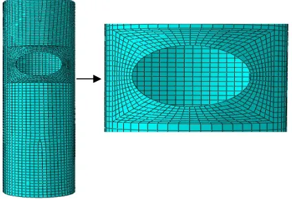
For this analysis, the nonlinear element S8R5, which is an eight-node element with six degrees of freedom per node, was suitable for analysis of thin shells [20]. A part of the meshed specimen is shown in Fig. 4.
Fig. 4. A sample of FEM mesh.
Figure 5 shows buckling load versus element size in the region around the cutout for specimen D42-L250-L0125-18×26. Buckling load decreased with decreasing element size and converged to real buckling load. In this paper, numerical analysis was done with the optimum element size of equal to 0.003m around the cutout.
Fig. 5. Buckling load versus element size for different sizes of the element around the cutout for specimen D42-L250-L0175-18×26.
2.4. Analytical process
17 information on these FE analyses, Shariati and
Mahdizadeh (2008) and ABAQUS user manual can be referred to [20].
3. Experimental instrument
Experimental tests were conducted by an Instron 8802 machine. The specimens were constrained by fixtures designed for this result and inserted in both ends, which mimicked the fixed boundary conditions used in the finite element simulations (see Fig. 7). Three specimens were tested for each case and almost
identical results were obtained compared to those obtained from the numerical simulations. 4. Results and discussion
4.1. Experimental verification
The experimental tests were conducted to verify some of the cases investigated in the numerical simulations. In this section, numerical analysis and experimental tests were done with α=15° and θ=0°.
The experimental results were compared to numerical findings in Table 1. The comparison
Fig. 6. Buckling mode shapes for specimen D42-L250-L0175-18×22: (a) first mode, (b) second mode, (c) third
mode.
Fig. 7.INSTRON 8802 machine and designed fixtures.
JCARME Abdolhossein Fereidoon, et al. Vol. 3, No. 1, Autumn 2013
18
Table 1. Comparison of the experimental and numerical results.
Model designation Buckling Load (Experimental) (N)
Buckling Load (FEM Result)
(N)
Error
(%)
D42-L250-L0125-18×22 34332.83 33641.52 2.1
D42-L250- L0125-18×26 32774.54 32483.85 1.0
D42-L150- L0125-18×26 35127.90 33024.83 5.9
showed little difference between the two sets of data.
The mean difference between the numerical calculations and experimental results was 3% of experimental buckling load.
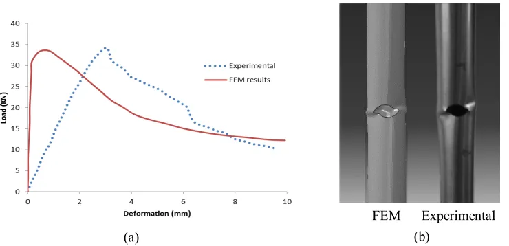
The load-displacement curves of lower point of the shell and deformed shape of the specimens in the buckling and post-buckling states in numerical and experimental tests are compared in Figs. 8 and 9. It can be seen that peak load of both curves were very close to each other while slope of linear part of load-displacement curves was higher in numerical analysis than in the experimental results, which may be due to the presence of internal defects in the material which reduced stiffness of the specimens in the
experimental method while the materials were assumed to be ideal in the numerical analysis. Deformed shapes of experimental and numerical results in post-buckling states are shown in Figs. 8(b) and 9(b). They demonstrated that deformations of cylindrical shells around the cutout in numerical and experimental analyses were almost identical.
4.2. Results of numerical analysis
In this section, results of the buckling analysis of cylindrical shells with elliptical cutouts of different sizes and angles are presented using finite element method. In numerical analysis according to Fig. 3, the shell angle was α=15°.
Fig. 8. Comparison of the experimental and numerical results for the specimen D42-L250-L0125-a18-b22:(a) load-displacement curves and (b)deformed shapes.
(b) (a)
19 Fig. 9. Comparison of the experimental and numerical results for the specimen D42-L250-L0125-a18-b26:(a) load-displacement curves and (b) deformed shapes.
4.2.1. The effects of cutout size, cutout position
4.2.1.1. Analysis of the effect of change in cutoutwidth on the buckling load
In this section, effect of changing cutout width on the buckling load of cylindrical shells is
studied. For this reason, cutouts with fixed height (18 mm) were created in the mid-height position of shells with θ=0° according to Fig. 1. Then, by changing width of the cutouts from 18 to 26 mm, the change in buckling load was studied. The results of this analysis are presented in Table 2.
Table 2. Summary of numerical analysis for cylindrical shells with different cutout widths, with elliptical cutout situated in various locations.
Model designation Shell thickness (mm)
Shell angle, α (degree)
Location of cutout (L0/L)
Buckling Load (N) D42-L250-L0125-18×18 1 15 0.5000 34662.62 D42-L250-L083.3-18×18 1 15 0.3333 34839.27 D42-L250-L062.5-18×18 1 15 0.2500 34979.96 D42-L250-L0125-18×20 1 15 0.5000 34208.38 D42-L250-L083.3-18×20 1 15 0.3333 34260.86 D42-L250-L062.5-18×20 1 15 0.2500 34583.72 D42-L250- L0125-18×22 1 15 0.5000 33641.60 D42-L250- L083.3-18×22 1 15 0.3333 33761.76 D42-L250- L062.5-18×22 1 15 0.2500 33916.14 D42-L250- L0125-18×24 1 15 0.5000 33102.93 D42-L250- L083.3-18×24 1 15 0.3333 33278.63 D42-L250- L062.5-18×24 1 15 0.2500 33373.87 D42-L250- L0125-18×26 1 15 0.5000 32483.85 D42-L250- L083.3-18×26 1 15 0.3333 32573.27 D42-L250- L062.5-18×26 1 15 0.2500 32715.24
(a) (b)
JCARME Abdolhossein Fereidoon, et al. Vol. 3, No. 1, Autumn 2013
20
Fig. 10(a) shows load-displacement curves of lower point of the shell for specimens with different cutout widths. The maximum values in these curves were the buckling loads. It can be seen that the buckling load of the shell decreased considerably when a cutout was created in the shell. The stress contours corresponded to specified points of A, Band C for specimen D42-L250-L0125-18×26, as shown in Fig. 10(b). It can be seen that stresses were symmetrical in the specimen with a cutout in mid height position. The stress on side of the shell with cutout was smaller than another side. The regions around the cutout were yielded before the load reached the maximum value. At
this time, local bending occurred in the regions around the cutout and then the shell experienced global bending.
The buckling load versus b/a and L0/L ratios curves are shown in Figs. 11(a) and 11(b), respectively. It is evident from Fig. 11(a) that an increase in the cutout width, when cutout height was constant, caused considerable reduction in the buckling load contrary to the reverse state which had little effect on buckling resistance of the shells. Figure 11(b) shows that, with changing position of the cutout from edges toward the mid height of the shell, the buckling load decreased.
Fig. 10.(a) Load vs. displacement curves of the specimens D42-L250 with a cutout a=18mm and b=26mm in
various locations and perfect specimen (b) von Mises stress stages at three points for the specimen D42-L250-L0125-18×26.
A B
C
A B C
(a)
21 Fig. 11. Buckling capacity of cylindrical shells vs.: (a) b/a and (b) L0/L for elliptical cutout with constant heights and various widths and locations.
4.2.1.2. Analysis of the effect of change in cutoutheight (a) on the buckling load
To study effect of a change in cutout height on the buckling load of cylindrical shells, cutouts with constant width (b=26 mm) were created in the mid-height position of shells with θ=0°. Then, with changing height of the cutouts from a=14 to 22 mm, the change in buckling load was studied. The results of the analysis are shown in Table 3. Furthermore, buckling load versus displacement curves produced from the FEM are shown in Fig. 12. Figure 12 shows
that, with increasing cutout height, the buckling load decreased.
4.2.1.3. Analysis of the effect of change in dimensions of fixed-area cutouts on the buckling behavior
In the previous sections, buckling behavior of the cylindrical shells was studied by changing e height or width of the cutout and, in each case, another dimension was kept constant. In this section, both width and height are changed so that the product of height and width, as the representative of the cutout area, remained
Table 3. Summary of numerical analysis for cylindrical shells with different cutout heights, with elliptical cutout situated at mid height of the shell.
Model designation Shell thickness
(mm)
Shell angle, α
(degree)
Cutout size a×b
(mm×mm)
Buckling Load
(N)
D42-L250-perfect 1 15 - 38223.89
D42-L250-L0125-14×26 1 15 14×26 32679.13
D42-L250- L0125-16×26 1 15 16×26 32564.84
D42-L250- L0125-18×26 1 15 18×26 32483.85
D42-L250- L0125-20×26 1 15 20×26 32432.13
D42-L250- L0125-22×26 1 15 22×26 32393.73
JCARME Abdolhossein Fereidoon, et al. Vol. 3, No. 1, Autumn 2013
22
Fig. 12. Load vs. displacement curves of the specimens D42-L250-L0125 with a cutout b=26mm and different
height of the cutout and perfect specimen.
constant. Therefore, cutouts with the area of A=117π mm2 were created in different positions of the shells with θ=0°. Four different values for cutout heights of between 18 and 26 mm were considered; the corresponding values for the cutout width were calculated so that the cutout area was constant.
Detailed information on the designed specimens and the analysis results are shown
in Table 4. The curves of the buckling load versus the b/a ratio are shown in Fig. 13. As expected, Fig. 13 shows that the buckling load decreased with increasing b/a ratio. Figure 14 demonstrates that shells with cutout position near the shell edge or lower L0/L ratio had a higher buckling load and they were more resistant to the buckle.
Table 4. Summary of numerical analyses for cylindrical shells with constant area, with elliptical cutout situated in various locations.
Model designation Shell thickness (mm)
Shell angle, α (degree)
Location of cutout (L0/L)
23 Fig. 13. Plots of buckling load vs. b/a for cylindrical
shells including an elliptical cutout with constant area for specimen D42-L250.
4.2.2. Analysis of the effect of change in cutout angle (θ) on the buckling behavior of cylindrical shells
In order to analyze the relationship between buckling load and changes in the angle of elliptical cutouts, an elliptical cutout of fixed size (18×26mm) was created in several positions of cylindrical shells with various angles between θ=0° and 90°. The results of this analysis are shown in Table 5.
The results showed that increasing the
Fig. 14. Plots of buckling load vs. Lo/L for cylindrical shells include an elliptical cutout with constant area for specimen D42-L250.
cutout angle enhanced shell resistance against buckling and increased amount of the critical load. Additionally, for cylindrical shells with cutout at L0=0.25L, changing angles from 0° to 90° increased the buckling load by 5.2%. The buckling load versus L0/L ratio curves is shown in Fig. 15. It can be seen that, with an increase in the cutout angle, buckling capacity of the shell increased. Also, for a cutout with fixed angle, the buckling load decreased with increasing Lo/L ratio.
Table 5. Summary of numerical analyses for cylindrical shells with various cutout angles, with elliptical cutout situated in various locations.
Model designation Shell thickness (mm)
Cutout angle, θ (degree)
Location of cutout (L0/L)
JCARME Abdolhossein Fereidoon, et al. Vol. 3, No. 1, Autumn 2013
24
Fig. 15. Plots of buckling load vs. ratio Lo/L for cylindrical shells including an elliptical cutout for specimen D42-L250-L0125-18×26 and various cutout angles.
5. Conclusions
The paper examined influence of elliptical cutouts of various sizes and angles and various L0/L ratios on the nonlinear response of stainless steel 316ti cylindrical shells subjected to axial compression load. A very good correlation was observed between results of the experimental and numerical simulations. In addition, the following results were found: 1. The peak load of load versus displacement curves of numerical and experimental results was near to each other. The mean difference of buckling load between the numerical and experimental results was 3% of the experimental buckling load.
2. Slop of linear part of load-displacement curves was higher in numerical analyses than in experimental results due to the presence of internal defects in the material, which reduced stiffness of the specimens in the experimental method.
3. The stress contours were symmetrical in the specimen with a cutout in mid height position. Also, the regions around the cutout yielded before the load reached the maximum value. 4. For cylindrical shells with a cutout, local bending occurred around the cutout and then global buckling was observed.
5. When the cutout width was constant and height of the cutout increased, the buckling load reduced. However, the amount of reduction in the buckling load was negligible.
6. Increasing width of the cutout while the cutout height was constant extremely decreased buckling load. Therefore, it is preferable to design shells in such a way that the greater dimension of the cutout is aligned with the longitudinal axis of the shell.
7. The buckling load decreased with increasing the width-to-height ratio of cutout in cylindrical shells with a cutout of fixed area. 8. For cylindrical shells with a cutout, changing the position of the cutout from edges toward the mid height of the shell caused reduction in the buckling load.
9. Also, increasing the cutout angle enhanced shell resistance and increased the buckling load.
References
[1] H. Shu, “The plastic limit load of circumferentially cracked thin walled pipes under axial force”, internal Pressure and Asymmetrical Bending,
International Journal of Pressure Vessels and Piping, Vol. 79, No. 5, pp. 377-382, (2002).
[2] F. Robert and S. Rahman, “Elastic-Plastic analysis of off-center cracks in cylindrical structures”, Engineering fracture mechanics, Vol. 66, No. 1, pp. 15-39, (2000).
[3] K. Yun-Jae and S. Do-Jun, “Approximate elastic-plastic J estimates of cylinders through wall cracks”, Engineering fracture mechanics, Vol. 71, No. 12, pp.1673-1693, (2004).
[4] Y. Meng-Kao, L. Meng-Chyuan and W. Wen-Tsang, “Buckling of an elastoplastic cylindrical shell with a cutout”,
Engineering Structures, Vol. 21, No. 11, pp. 996-1005, (1999).
[5] G. H. Rahimi and E. Poursaeeidi “Parametric study of plastic strength of cylindrical shells with cutout under axial loading and bending moment”, J. of mechanical Engineering, Iranian society of mechanical engineers, Vol. 1, pp. 504-512, (2004).
25 and axial compression load”, Int. J.
Pressure Vessel and Piping, Vol. 79, No. 5, pp. 351-359, (2002).
[7] A. Tafreshi and G. B. Colin, “Instability of imperfect composite cylindrical shells under combined loading”, Composite Structures, Vol. 80, No. 1, pp. 49-64, (2007).
[8] E. Poursaeeidi, G. H. Rahimi and A. H. Vafai, “Plastic buckling of cylindrical shells with cutouts”, Asian Journal of civil engineering (Building and housing), Vol. 5, No. 3-4, pp. 191-207, (2004). [9] B. J. Vartdal, S. T. S. Al-Hassani and S.
J. Burley, “A tube with a rectangular cutout. Part2: subject to axial compression”, Proc. IMech, 220 Part C: J. Mechanical Engineering Science, Vol. 220, No. 5, pp. 652-643, (2005).
[10] H. Han, J. Cheng and F. Taheri “Numerical and experimental investigations of the response of aluminum cylinders with a cutout subject to axial compression”, Thin-Walled Structures, Vol. 44, No. 2, pp. 254-270, (2006).
[11] M. Shariati and M. Mahdizadeh Rokhi, “Numerical and Experimental Investigations on Buckling of Steel Cylindrical Shells with Elliptical Cutout Subject to Axial Compression”, Thin-Walled Structures, Vol. 46, No. 11, pp. 1251-1261, (2008).
[12] M. Shariati and M. Mahdizadeh Rokhi, “Investigation of buckling of Steel cylindrical shells with elliptical cutout under bending moment”, International Review of Mechanical Engineering, Vol. 3, No. 1, pp. 7-15, (2009).
[13] D. C. Han and S. H. Park, “Collapse
behavior of square thin-walled columns subjected to oblique loads”, Thin-Walled Structures, Vol. 35, No. 3, pp. 167–184, (1999).
[14] M. Shariati, M. Sedighi, J. Saemi, H. R. Eipakchi and H. R. Allahbakhsh, “Numerical and experimental investigation on ultimate strength of cracked cylindrical shells subjected to combined loading”, Scientific Journal Mechanica, Vol. 84, No. 4, pp. 1392-1207, (2010).
[15] H. S. Kim and T. Wierzbicki, “Crush behavior of thin-walled prismatic columns under combined bending and compression”, Computers and Structures, Vol. 79, No. 15, pp. 1417-1432, (2001). [16] A. Reyes, M. Langseth and O. S.
Hopperstad, “Square aluminum tubes subjected to oblique loading”,
International Journal of Impact Engineering, Vol. 28, No. 10, pp. 1077-1106, (2003).
[17] B. Prabul, A. V. Raviprakash and N. Rathinam, “Parametric study on buckling behaviour of thin stainless steel cylindrical shells for circular dent dimensional variations under uniform axial compression”, International Journal of Engineering Science and Technology, Vol. 2, No. 4, pp. 134-149, (2010).
[18] J. Blachut, “Buckling of axially compressed Cylinder with Imperfect Length”, Computers and Structures, Vol. 88, No. 5-6, pp. 365-374, (2010).
[19] ASTM A370-05, “Standard test methods and definitions for mechanical testing of steel products”.