Experimental Studies of Double Pipe Helical Coil
Heat Exchanger with Micro Fins
Patil Amar .B Dange H. M
Department of Mechanical Engineering Department of Mechanical Engineering
KIT’s College of engineering, Maharashtra, India PVPIT College of engineering, Budhgaon Maharashtra, India
Abstract
This paper revel’s the heat transfer characteristics, flow friction characteristics, of a horizontal tube-in-tube heat exchanger for single phase heat transfer with water as the working fluid. The material used for the construction of heat exchanger is copper, owing to its high thermal conductivity. The various techniques for achieving improved heat transfer are usually referred to as “heat transfer augmentation” or “heat transfer enhancement” and the heat exchanger provided with heat transfer enhancement techniques as “Augmented Heat Exchanger”. The objective is to reduce as many of the factors as possible capital cost, power cost, maintenance cost, space and weight, consistent with safety and reliability. Paper describes the principal techniques of industrial importance for the augmentation of single phase heat transfer on the inside of tubes namely “Micro fin’’. So micro fins should be used in heat exchanger when high heat transfer rate is required and pressure drop is of no significance. The obtained results show that the Nusselt number in the tube with the micro fin increases. It was observed that, based on constant flow rate, the heat transfer rates for finned heat exchanger were found to be more than the plain tube.
Keywords: Nusselt number, Prandalt number, heat exchanger, micro fins
_______________________________________________________________________________________________________
I.
I
NTRODUCTIONHeat exchangers are devices that facilitate the exchange of heat energy between two fluids that are at different temperatures while keeping them from mixing with each other. Heat exchangers are used in different processes ranging from conversion, utilization & recovery of thermal energy in various industrial, commercial & domestic applications. Some common examples include steam generation & condensation in power & cogeneration plants; sensible heating & cooling in thermal processing of chemical, pharmaceutical & agricultural products; fluid heating in manufacturing & waste heat recovery etc. Increase in Heat exchanger’s performance can lead to more economical design of heat exchanger which can help to make energy, material & cost savings related to a heat exchange process[3].
Helical coil heat exchangers are one of the most common equipment found in many industrial applications ranging from chemical and food industries, power production, electronics, environmental engineering, air-conditioning, waste heat recovery. The development of the flow in the helically coiled tubes is due to the centrifugal forces. The curvature of the tube produces a secondary flow field with a circulatory motion, which causes the fluid particles to move toward the core region of the tube. The secondary flow increases heat transfer rates and it reduces the temperature gradient across the cross-section of the tube. There is additional convective heat transfer mechanism, perpendicular to the main flow, which does not exist in conventional heat exchangers [5].
II.
E
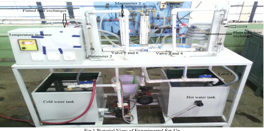
XPERIMENTAL INVESTIGATIONFig.1 Pictorial View of Experimental Set-Up
A schematic diagram of the experimental apparatus is shown in Fig.1 it consists of a test section, hot water tank, and cold water tank and data acquisition system. The details of the double fined tube heat exchanger are shown in Fig. 2. The close-loops of hot and cold water consist of the electric heaters controlled by adjusting the temperature. Water is used as the medium for cooling the hot water. The hot water is adjusted to the desired level and controlled by a temperature controller. The temperatures of the cold and hot water were adjusted to achieve the desired level. The water and tube wall temperatures at the inlet, middle and outlet sections are measured by four K type thermocouples.
Specifications Experimental set-up A.
The experimental study on passive heat transfer augmentation using micro fins were carried out in a double pipe heat exchanger. The dimension and specification for experimental work are based on literature review used for heat enhancement techniques. The specifications as listed below in table no 1.
Table No 1
Dimensions of Double Pipe Heat Exchanger
Dimensions Outer Tube Inner Tube Outer Diameter (m) 0.0254 0.0127
Wall Thickness (m) 0.0015 0.0015
Active Turns 4 4
Coil Diameter (m) 0.24 0.24 Reynolds No ranges 200-9000 200-9000
Prandtl Number 5 5
Coil Pitch (m) 0.02 Concentric with outer tube Material of Construction MS Copper
Velocity (m/s) 0.09-0.16 0.004-0.024
Experimental Procedure B.
Experiments were performed with various inlet temperatures and flow rates of hot water entering the test section. In the experiments, the hot water flow rate was increased in inner tube, while the cold water flow rate, and were kept constant. The inlet hot water temperatures were adjusted to achieve the desired level of temperature by using electric heaters controlled by temperature controllers and kept cold water temperature constant. Before any data were recorded, the system was allowed to approach the steady state. The flow rates of the water are controlled by adjusting the valve and measured by two calibrated flow meters with a range of 0–0.020 kg/s. One heat exchangers made with micro fins and other was without micro fins. For both heat exchangers we take inlet/outlet temperatures of inner tube and outer tube.
Experimental Procedure of setup given below,
First filled water in hot water tank up to certain level, and switch ON electric supply to water heater.
Start mono block to pump hot water from hot water tank and circulate in inner tube. The mass flow rate of hot water is controlled by the flow control valve 1 (FCV) and flow measured by the Rota meter 1.
For same time mass flow rate of cold water or annulus side flow is controlled by the flow control valve 2 and flow measured by the Rota meter 2. The annulus side cold water received from the large cold-water reservoir.
The test was conducted for counter-flow configuration.
For first observation, keep inner tube side mass flow rate was 100 LPH and outer tube side mass flow rate maintained 100 LPH. Likewise vary the outer tube side mass flow rate (100 to 600 LPH) and keep inner side mass flow rates was constant. Take inlet-outlet temperatures, pressure drop (mercury difference) and mass flow rates in observation table. For next observation, likewise vary the tube side mass flow rate and keep annulus side mass flow rate is constant. Take
inlet-outlet temperatures, mass flow rates and head loss due to friction in observation table. This procedure is continuous for all readings.
Hot water outlet again circulates to hot water tank, so that water heater conserves the energy.
Next, change heat exchanger, repeat it above procedure for various mass flow rates, and take observations.
Material selection for Test Section C.
An important design aspect of heat exchanger technology is the selection of appropriate materials to conduct and transfer heat fast and efficiently. The Copper material is selected for inner tube. It has many desirable properties for thermally efficient and durable heat exchangers. First and foremost, copper is an excellent conductor of heat. This means that copper's high thermal conductivity allows heat to pass through it quickly. Other desirable properties of copper in heat exchangers include its corrosion resistance, bio fouling resistance, maximum allowable stress and internal pressure, creep rupture strength, fatigue strength, hardness, thermal expansion, antimicrobial properties, tensile strength, antimicrobial properties, yield strength, high melting point, alloy ability, ease of fabrication, and ease of joining[7].
The performance advantages of copper as a heat transfer material include greater heat exchange, better long-term durability and resistance to corrosion, lower cost of maintenance, and copper’s antimicrobial benefits. A unique highlight of Micro Groove technology is that heat transfer is enhanced by grooving the inside surface of the tube. This increases the surface to volume ratio, mixes the refrigerant, and homogenizes refrigerant temperatures across the tube.
The mild steel material is selected for outer tube. The reason for the selection of Stainless steel material are due to its desirable properties such as mild steel material good strength characteristics in low temperature and high temperature service, resistance to corrosion in different chemical environment, resistance to fouling due to corrosion, maintain excellent heat transfer properties in service, ease of fabrication and available in variety of composition at economical cost. Selection of material for components is given in table 2.
Table II
Thermal Conductivity of Cu and Ms Material.
Sr .No. Material Thermal Conductivity (W/m K)
1 Cu 385.0
2 MS 45
III.
R
ESULTS AND DISCUSSIONThe experimental studies are conducted for single-phase water to water heat transfer application. The double pipe heat exchanger has been analyzed in terms of temperature variation for micro fins. The results obtained from the experimental investigation of heat exchanger operated at various operating conditions are studied in detail and presented. The thermal performance of the double pipe heat exchanger is evaluated in heat transfer rate, overall heat transfer coefficients and Nusselt numbers. The tube side flow rate is varied from the 100 LPH to 600 LPH same time annulus side flow rate is maintained constant. The test is conducted for only the counter-flow configuration. Six annulus side flow rates are taken 100, 200, 300, 400, 500 and 600 LPH.
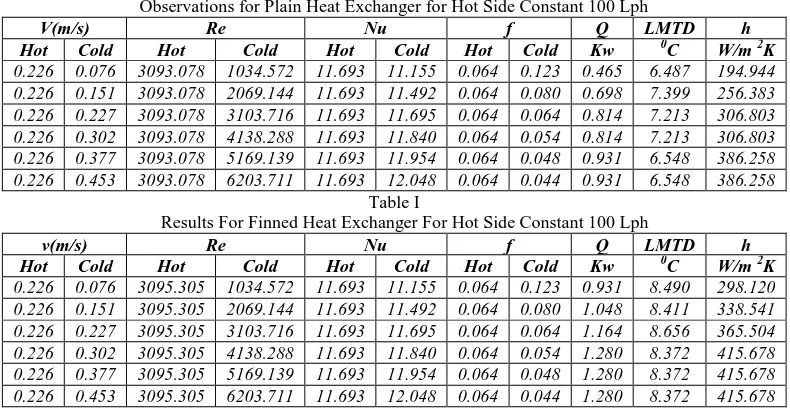
Table. III
Observations for Plain Heat Exchanger for Hot Side Constant 100 Lph
V(m/s) Re Nu f Q LMTD h
Hot Cold Hot Cold Hot Cold Hot Cold Kw 0C W/m 2K 0.226 0.076 3093.078 1034.572 11.693 11.155 0.064 0.123 0.465 6.487 194.944 0.226 0.151 3093.078 2069.144 11.693 11.492 0.064 0.080 0.698 7.399 256.383 0.226 0.227 3093.078 3103.716 11.693 11.695 0.064 0.064 0.814 7.213 306.803 0.226 0.302 3093.078 4138.288 11.693 11.840 0.064 0.054 0.814 7.213 306.803 0.226 0.377 3093.078 5169.139 11.693 11.954 0.064 0.048 0.931 6.548 386.258 0.226 0.453 3093.078 6203.711 11.693 12.048 0.064 0.044 0.931 6.548 386.258
Table I
Results For Finned Heat Exchanger For Hot Side Constant 100 Lph
v(m/s) Re Nu f Q LMTD h
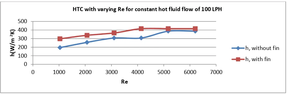
Fig. 2: HTC With Varying Re For Constant Hot Fluid Flow Of 100 LPH
Fig. 2 shows the relationships between the h and the Reynolds number for plain and finned heat exchangers. Heat transfer coefficient increases with increase in Reynolds number. With the increase in Reynolds number the turbulence increases which in turns increases the h. From Table II and Table III it can be clearly observed that finned exchanger having more heat transfer coefficient than plain heat exchanger due to increase in heat transfer area.
Similarly we have varied mass flow rate up to 100 LPH TO 600 LPH for both of the finned and plain heat exchanger and we found satisfactory results.
Heat transfer rate with varying flow rates A.
Fig. 3 shows that variation of heat transfer rate with varying cold flow rate by keeping constant hot fluid flow through plain heat exchanger.
Fig. 3: Variation of Heat Transfer Rate with Varying Cold Flow Rate
When 100 LPH,200 LPH and 300 LPH hot fluid constantly flows through inner tube and varying flow rate from 100 LPH to 600 LPH of cold fluid through outer tube then small increase in heat transfer rate was observed but for 500 LPH and 600 LPH heat transfer rate more increases.
Fig. 4 shows that variation of heat transfer rate with varying hot flow rate by keeping constant cold fluid flow through plain heat exchanger.
Fig. 4 Heat Transfer Rate with Varying Flow Rates Of Hot Fluid
0 100 200 300 400 500
0 1000 2000 3000 4000 5000 6000 7000
h
(W/m
2K)
Re
HTC with varying Re for constant hot fluid flow of 100 LPH
h, without fin
h, with fin
0 1 2 3 4
0 100 200 300 400 500 600 700
Q,
k
W
cold fluid flow rate, (LPH)
Heat transfer rate with varying flow rates of cold fluid
100 LPH hot
200 LPH hot
300 LPH hot
400 LPH hot
500 LPH hot
600 LPH hot
0 1 2 3 4 5
0 100 200 300 400 500 600 700
Q,
k
W
hot fluid flow rate, (LPH)
Heat transfer rate with varying flow rates of hot fluid
When 100 LPH cold fluid constantly flows through outer tube and varying flow rate from 100 LPH to 500 LPH of hot fluid through inner tube then small increase in heat transfer rate was observed but for 600 LPH heat transfer rate decreases. For 200 LPH, 400 LPH and 600 LPH constantly increase in heat transfer rate. For 300 LPH heat transfer rate was more compare to 100, 200, 400, 500 and 600 LPH.
IV.
C
ONCLUSIONExperimental study of Double pipe heat exchanger was performed using with and without micro fin. The results will show comparison between with and without micro-fin helical coil heat exchanger. The plain heat exchanger and finned heat exchanger were tested for counter flow configuration using water as working fluid with single phase heat transfer was studied. The effects of parameters such as Reynolds number on the heat transfer and overall enhancement ratio were studied.
The conclusions from experimentation work are drawn as follows,
In a heat exchanger, while the inserts can be used to enhance the heat transfer rate, they also bring in an increase in the pressure drop. When the pressure drop increases, the pumping power cost also increases, thereby increasing the operating cost. So depending on the requirement, one of the above mentioned inserts can be used for heat transfer augmentation.
The heat transfer rates for finned heat exchanger were 40% higher than the plain heat exchanger.
Use of a helical coil heat exchanger was seen to increase the heat transfer coefficient up to 20% compared to a similarly dimensioned straight tube heat exchanger.
Flow rate did not affect the heat transfer coefficient, most likely from the fact that the flow was turbulent and increasing the flow rate does not greatly change the wall effects.
In a heat exchanger, while the inserts can be used to enhance the heat transfer rate, they also bring in an increase in the pressure drop. When the pressure drop increases, the pumping power cost also increases, thereby increasing the operating cost. So depending on the requirement, one of the above mentioned inserts can be used for heat transfer augmentation.
On the basis of performance evaluation criteria based on constant flow rate , we can say that the , the micro fin heat exchanger gives the highest maximum value of heat transfer rate 20% more than Plain tube.
R
EFERENCES[1] VentsislavZimparov, “Enhancement of heat transfer by a combination of three start spirally corrugated tubes with a twisted tape”, International Journal of
Heat and Mass Transfer 44 (2001) 551-574
[2] D. G. Prabhanjan, “Comparison of heat transfer rates between a straight tube heat exchanger and a helically coiled heat exchanger”, lnt. Comm.
HcnrMas.sTnm& Vol. 29. No. 2. pp. 185-191, (2002)
[3] EbruKavakAkpinar, “Heat transfer enhancements in concentric double pipe exchanger equipped with swirl elements”, Int. Comm. Heat mass transfer,
vol.31,No 6, pp.857-868, (2004)
[4] Timothy J. Rennie, Vijaya G.S. Raghavan, “Experimental studies of a double-pipe helical heat exchanger”, Experimental Thermal and Fluid Science 29 (2005), pp.919–924.
[5] Vimal Kumar, “Numerical studies of a tube-in-tube helically coiled heat exchanger”, Chemical Engineering and Processing 47 (2008) 2287–2295
[6] Smith Eiamsa-ard, SomsakPethkool, ChinarukThianpong b, PongjetPromvonge “Turbulent flow heat transfer and pressure loss in a double pipe heat
exchanger with louvered strip inserts” International Communications in Heat and Mass Transfer 35 (2008) 120–129
[7] Prabhata K. Swamee, NitinAggarwal, Vijay Aggarwal , “Optimum design of double pipe heat exchanger” International Journal of Heat and Mass Transfer
51 (2008) 2260–2266.
[8] MansoorSiddique, MajedAlhazmy, “Experimental study of turbulent single-phase flow and heat transfer inside a micro-finned tube”, international journal