Vol. 7, No. 2, 2014,35-44
ISSN: 2279-087X (P), 2279-0888(online) Published on 29 August 2014
www.researchmathsci.org
Annals of
Numerical Simulation on MHD Free Convection Mass
and Heat Transfer Fluid Flow over a Vertical Porous
Plate in a Rotating System with Induced Magnetic Field
Md. Mizanur Rahman1*, Md. Abdul Hye2 , Md. Mostafizur Rahman3 and
Md. Mahafujur Rahaman4
1, 3
Department of Mathematics, Faculty of Applied Science and Technology Islamic University, Kushtia-7003, Bangladesh
Email:1mizan_iu@yahoo.com; Email: 3mmr7764.iu@gmail.com
2
Department of Mathematics & Statistics, Bangladesh University of Business & Technology Dhaka – 1216, Bangladesh; Email:2abdul@bubt.edu.bd
4
Z.H.Sikder University of Science & Technology, Shariatpur-8024, Bangladesh Email:4mahfuz0809@gmail.com
Received 21 July 2014; accepted 6 August 2014
Abstract. The MHD free convection fluid flow with the Soret effect on the combined heat and mass transfer unsteady flow past a continuously moving semi-infinite vertical porous plate in a rotating system has been investigated numerically under the action of induce magnetic field. This study is performed for cooling problem with lighter and heavier particles. Numerical solutions for the primary velocity field, secondary velocity field, temperature distribution as well as concentration distribution are obtained by using the explicit finite difference method. The obtained results to observe the effects of various parameters are shown graphically. Finally, the important findings of the investigation are concluded.
Keywords: MHD, rotating system, mass and heat transfer, hall current, finite difference method
AMS Mathematics Subject Classification (2010): 76Dxx, 76D99, 76E09
1. Introduction
Md. M.Rahman Md. A.Hye, Md. M.Rahmanand Md. M. Rahman
characters. General boundary layer equations for continuous surfaces have been developed by Sakiadis [1].
Agarwal et al. [2] studied the effects of Hall Current on the hydro-magnetic free convection with mass transfer in a rotating fluid. Takhar and Ram [3] studied the effects of Hall current on hydro-magnetic free convective flow through a porous medium. Chaudhary and Sharma [4] have analytically analyzed the steady combined heat and mass transfer flow with induced magnetic field. Bhaskar Kalita [5] investigate the magnetic field effect on unsteady free convection MHD flow between two heated vertical plate. Dileep and Priyanka [6] studied the effects on heat transfer of rotating cautte flow in a channel partially filled by a porous medium with hall current. B. P. Garg [7] studied combined effects of thermal radiations and hall current on moving vertical porous plate in a rotating system with variable temperature. Sahin et al. [8] established a mathematical model on magneto- hydro-dynamic transient free and forced convective flow with induced magnetic field effects. Magneto-hydrodynamic flow and heat transfer of two immiscible fluids with induced magnetic field effects is investigated by Zivonin et al. [9] Dufour and Soret Effects On Steady MHD Free Convection And Mass Transfer Fluid Flow Through A Porous Medium in A Rotating System have been investigated by Nazmul and Alam [10]. Sandeep et al [11] investigated the effect of inclined magnetic field on unsteady free convection flow of dissipative fluid past a vertical plate. Seth et al. [12] studied Effect of Rotation on Unsteady Hydromagnetic Natural Convection Flow Past an Impulsively Moving Vertical Plate with Ramped Temperature in a Porous Medium with Thermal Diffusion and Heat Absorption. Rajput and Kumar [13] investigated the Rotation and Radiation Eects on MHD Flow Past an Impulsively Started Vertical Plate with Variable Temperature. The main objective of the present study is to investigate numerically MHD Free Convection fluid flow over a Vertical Porous Plate in a Rotating System in the presence of Soret effect, hall effect, Mass and Heat transfer effectwith Induced Magnetic Field.
2. Mathematical formulation
Let us consider a unsteady MHD combined heat and mass transfer by free convection flow of an electrically conducting incompressible viscous fluid past an electrically nonconducting continuously moving semi-infinite vertical porous plate. The flow is assumed to be in the x-direction which is taken along the porous plate in upward direction and y-axis is normal to it. Since flow is in only x-direction and the plate is semi-infinite so = 0. A strong uniform magnetic field is applied normal to the plate that induced another magnetic field on the electrically conducting fluid.
Initially we consider that the plates as well as the fluid are at the same temperature T = (T∞) and the concentration level C = (C∞) everywhere in the fluid is same. Also it is assumed that the fluid and the plate is at rest after that the plate is to be moving with a constant velocity U in its own plane and instantaneously at time t > 0, the temperature of the plate and the species concentration are raised to T(> T∞) and C= (C∞) respectively, which are thereafter maintained constant, where T, C are the
temperature and species concentration at the wall and T∞, C∞ are the temperature and
The x-component momentum of equation reduces to the boundary layer equation if the only contribution to the body force is made by gravity, the body force per unit volume,F = −g where g is the local acceleration due to gravity. There is no body force in the y-direction and z-direction i.e. F= 0 F= 0. Thus and which implies that P = P(x). Hence the x-component pressure gradient at any point in the boundary layer must equal to the pressure gradient in the quiescent region outside the boundary layer. However, in this region u = v = 0. Initially the fluid as well as the plate is at rest, after that the whole system is allowed to rotate with a constant angular velocity
Ω about the y-axis. Since the system rotates abouty−axis, so we can take
(
0,−Ω,0)
=
Ω . A uniform transverse magnetic field of magnitude B0is applied in the
direction ofy−axis. The physical configuration of the problem is furnished in Figure 1.
Within the framework of the above-stated assumptions the generalized equations relevant to the unsteady problem are governed by
the equation of continuity yields
∇. q = 0 i.e. ++ = 0 (1) The Momentum equation for a viscous compressible fluid in vector form is
!+(q. ∇)q + 2Ω× q = F − $
ρ∇P + %∇
&q (2)
where F = (F, F, F) is the body force per unit mass; P is the fluid pressure and ' is the kinematic viscosity.
Now we apply a strong magnetic field B that induced another magnetic field on the electrically conducting fluid. As a result the equation (2) becomes as a magneto- hydrodynamic(MHD) equation in the following form
! +(q. ∇)q + 2Ω× q = F−$ρ∇P +υ∇
&+$
ρ(J × B) (3)
where J = (J,J,J,) is the current density. The MHD energy equation for a viscous incompressible electrically conducting fluid with viscous dissipation and Joule heating term is
*
!+ (q. ∇)T =
κ ρ+, ∇
&T + -.
ρ+,σµ/.+
$
σ+, φ
(4) where T is the fluid temperature, C0 is the specific heat at the constant pressure and 1 is the thermal conductivity and
φ=µ[2 345&+ 45&+ 45&6 +
4+5&+ 4+5&+ 4+5&] Also φ denotes the dissipation function involving the viscous stress and the MHD species equation for a viscous incompressible electrically conducting fluid
Figure1. Physical configuration and
Md. M.Rahman Md. A.Hye, Md. M.Rahmanand Md. M. Rahman is
7
!+(q. ∇)C = D9∇&C+ :;κ<
*; ∇
&T (5)
The MHD generalized Ohm’s law is of the form J =σ(E + q × B) −>?σ
/(J × B) +
σ
>?/∇P> (6)
where E is the electric field intensity, P> is the pressure of the electron, e is the charge of electron and n> is the number density of electrons.
Gauss’s law of magnetism
A.B=0 (7) Now
Ω× q =Ωwı̂ −ΩukF (8) The equation (7) is satiesfied by
B = B ȷ̂ (9) So the equation of Ohm’s law becomes
J+H9
I(J × B) =σ(q × B) (10)
where m =ω>τ> is the Hall parameter.
J × B = −B Jı̂ + B JkF (11) q × B = −B wı̂ + B ukF (12) Now from equation (10), (11), (12), we get
Jı̂ + Jȷ̂ + JkF +H9IK−B Jı̂ + B JkFL = σ(−B wı̂ + B ukF ) (13) Now equating the coefficient of i, j, k and solving, we get
J = σHI$N9(9M). , J= 0, J = σHI$N9(N9). .
J × B=−σHI.$N9(N9). ı̂ +σHI.$N9(9M). kF (14) In two-dimensional Cartesian coordinate system the continuity equation (1), the momentum equations (3), the MHD energy equation (4) and the MHD species equation (5) are as follows
Continuity equation
+= 0 (15)
Momentum equation
!+ u+ v+ 2Ωw = Oβ(T − T∞) + Oβ∗(C − C∞) +υ
.
.−
σHI.
ρ($N9.)(u + mw) (16)
! + u
+ v
− 2Ωu=υ
.
. +
σHI.
ρ($N9.)(mu − w) (17)
Magnetic induction equation
T t+u
T x+v
T y=
κ ρcp
2T
y2+
υ
cp{4
u y5
2
+ 4w y5
2
} (18) Species equation
C t +u
C x+v
C y = Dm
2C
y2+ Dmκt
Tm
2T
y2 (19)
With the corresponding initial and boundary conditions are u=0, w=0, T=Tw, C=Cw at y=0
u=0, w=0,T→T∞,C→C∞asy→∞ (20)
X= xU0
υ , Y=
yU0
υ ,U=
u U0,V=
v
U0 , W=
w U0, τ=
tU02
υ, TT=
TMT∞
TwMT∞ ,C T= CMC∞
CwMC∞. From the above dimensionless variable we have
x= υX
U0, y=
υY
U0, u= U0U, v= U0V, w= U0W, T= T∞+ (Tw−T∞)T T and C=C∞+ (Cw−C∞)CT.
Then the continuity equation, the momentum equations, the energy equation and the concentration species equation reduces to the form
U X+
V
Y=0 (21) U
τ+ U
U X +V
U
Y= GrTT +GmCT+ 2U
Y2− M
(1Nm2)(U+mW)−R
′W (22)
W τ+ U
W X +V
W
Y= 2W
Y2+ M
(1Nm2)(mU−W)+R
′U (23)
TT τ+ U
TT X +V
TT Y=
1 Pr
2TT
Y2+Ec{( U Y)
2+ (W Y)
2} (24) CT
τ+ U
CT X +V
CT Y=
1 Sc
2CT
Y2+S0 2TT
Y2 (25)
where Gr=
υgβ(TwMT∞)
U03
( Grashof Number ), Gm=
υgβ∗(TwMT∞)
U03
(Modified Grashof Number ),
M= συB02
ρU02
( Magnetic Parameter ), R′= 2υΩ
U02
(Rotational parameter), Pr=
υρCp
κ , (Prandtl
Number), Ec= U02
Cp(TwMT∞) (Eckert Number ), Sc =
υ
Dm (Schmidt Number) And S0=
DmκT(TwMT∞)
υTm(CwUC∞) ( Soret Number ).
Also the associated initial and boundary conditions become U=0, W=0, TT =1, CT =1 at Y=0
U=0, W=0, TT =0, CT =0 as Y→∞ (26)
3. Numerical solutions
The system of non-dimensional, nonlinear, coupled partial differential equations (21)-(25) with boundary condition (26) are solved numerically using explicit finite difference method. To obtain the difference equations, the region of the flow is divided into a grid or mesh of lines parallel to X and Y axes, where X -axis is taken along the plate and Y-axis is normal to the plate.
Here the plate of height Xmax
(
=100)
is considered i.e. X varies from 0 to 100 and assumed( )
30
max
=
Y
as corresponding to Y→∞ i.e. Y varies from 0 to 30. There are m(
=150)
and n(
=150)
grid spacing in the X and Y directions respectively as shown in Figure 2. It is assumed that ∆X , ∆Y are
content mesh size along X and Y directions respectively and taken as follows,
Figure2. Explicit finite
Md. M.Rahman Md. A.Hye, Md. M.Rahmanand Md. M. Rahman
(
0 100)
50.
0 ≤ ≤
=
∆X X and ∆Y =0.15
(
0≤Y ≤30)
with the smaller time-step, 005. 0
= ∆τ .
Let
U
′
,
W
′
,
T
′
and
C
′
denote the values of U,W,T and C are the end of a time-step respectively. Using the explicit finite difference approximation, the following appropriate set of finite difference equations are obtained as;0 1 , , , 1 , = ∆ − − + ∆ − ′ − ′ Y j i V j i V X j i U j i U (27)
( )
2 r i,j m 2 i,j i,j i,j 1 j i, j i, 1 j i, j i, 1 j i, j i, j 1, i j i, j i, j i, j i, W R ) mW (U ) m (1 M C G T G ∆Y U 2U U ∆Y U U V ∆X U U U ∆τ U U ′ − + + − ′ + ′ + + − = − + − + − ′ − + + − (28)( ) ij
j i j i j i j i j i j i j i j i U R Y W W V X W W U W W ′ −− − + + + − = ∆ − + ∆ − + ∆ − ′ − + + − ) W (mU ) m (1 M ∆Y W 2W W j i, j i, 2 2 1 j i, j i, 1 j i, , 1 , , , 1 , , , , τ (29)
( )
2 Ec{( }∆Y 1 j i, T j i, T 2 1 j i, T r P 1 ∆Y j i, T 1 j i, T j i, V ∆X j 1, i T j i, T j i, U ∆τ j i, T j i,
T i,j1 i,j 2 i,j1 i,j 2
) ∆Y W W ( ) ∆Y U U − + − + + + − + − + = − + + − − + − ′ (30)
( )
( )
21 j i, j i, 1 j i, 0 2 1 j i, j i, 1 j i, c j i, 1 j i, j i, j 1, i j i, j i, j 1, i j i, ∆Y T T 2 T S ∆Y C C 2 C S 1 ∆Y C C V ∆X C C U ∆τ C
C − − + + − + − + −
+ + − = − + − + − ′ (31)
with the boundary condition;
1 , 1 , 0 ,
0 ,0 ,0 ,0
0 , = = = = n i n i n i n
i W T C
U ∞ → = = =
=0, , 0, , 0, , 0whereL
, n L i n L i n L i n L
i W T C
U
(32)
Here the subscript i and j designates the grid points with X and Y coordinates respectively and the superscript n represents a value of time, τ =n∆τ where
... ,.... 2 , 1 , 0 =
4. Results and discussion
For the purpose of discussing the results of the problem, the approximate solutions are obtained for various parameters with small values of Eckert number. In order to analyze the physical situation of the model, we have computed the numerical values of the non-dimensional primary velocityV, secondary velocity W, temperature WX and concentration Y̅ within the boundary layer for different values of magnetic parameter [, Hall parameter m, Soret number \], Prandtal number ^_, Schmidt number \` and Eckert number a` with the fixed value of Grashof numberb_ and modified Grashof number bc. Along with the obtained steady state solutions, the flow behaviors in case of cooling problem are discussed graphically. The profiles of the primary velocity, Secondary velocity, temperature and species concentration versus Y are illustrated in Figs. 3-14 respectively.
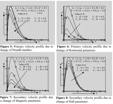
From the Figs. 3-6 we see that the primary velocity V distribution increases gradually near the plate and then decreases slowly far away from the plate. Also we see that it decreases with increasing Magnetic parameter, Hall effect parameter, Rational parameter, Prandtl number. The secondary velocity profiles d have been shown in Figs. 7-9. These results show that secondary velocity increases with increasing Hall parameter, Eckert number and decreases with increasing Magnetic parameter.
The temperature distributions have been illustrated for various values of Radiation parameter, Eckert number and Prandtl number in Figs. 10-12 respectively. We see that the temperature distributions increses with increasing Eckert number and decreases with increasing Rotational parameter, Prandtl number.
Figure 3: Primary velocity profile due to
change of Magnetic parameter.
Figure 4: Primary velocity profile due to change of Hall parameter.
0 10 20 30
0 0.5 1 1.5 2 2.5 3
1 1
1
1 2
2
2
2 3
3
3 4
4
4 00 10 20 30
0.5 1 1.5 2 2.5 3
1 1
1
1 2
2
2
2 3
3
3
3 4
4
4
4
Y U
1 … [ 0.2, 2 … [ 0.4 3 … [ 0.6, 4 … [ 0.8
Value of M
b_ 1, bc 1, k 0.1, lm 0.3 ^_ 0.7, a` 0.5, \` 0.4, \
0.3
Y U
1 … k 0.1, 2 … k 0.3 3 … k 0.5, 4 … k 0.7
Value of m
Md. M.RahmanMd. A.Hye, Md. M.Rahmanand Md. M. Rahman
Figure 5: Primary velocity profile due to change of Prandtl number.
Figure 6: Primary velocity profile due to change of Rotational parameter.
Figure 7: Secondary velocity profile due
to change of Magnetic parameter. Figure 8: Secondary velocity profile due to change of Hall parameter.
Figure 9: Secondary velocity profile due
to change of Eckert number.
Figure 10: Temperature profile due to change of Prandtl number.
0 10 20 30
0 0.5 1 1.5 2 2.5 3
1 1
1
1 2
2
2
2 3
3
3
3 4
4
4
4 00 10 20 30
1 2 3 4
1 1 1
1
2 2
2
2 3
3
3
4 4
0 10 20 30
0 0.5 1 1.5 2
1 1 1
1 2
2
2 3
3
3
4 4
0 10 20 30
0 0.5 1 1.5 2 2.5 3
1 1
1
1 2
2
2
2 3
3
3
3 4
4 4
4
0 10 20 30
0 0.5 1 1.5 2 2.5 3
1 1
1 2
2
2
2 3
3
3
3 4
4 4
4
0 10 20 30
0 0.5 1 1.5 2 2.5 3
1
1
1 2 2
2 3
3
3
3 4
4
4
4 Y
U
1 … ^_ 0.0, 2 … ^_ 0.2 3 … ^_ 0.7, 4 … ^_ 1.0
Value of ^_
b_ 1, bc 1, k 0.1, lm 0.3 [ 0.2, a` 0.5, \` 0.4, \
0.3
Y U
1 … lm 0.0, 2 … lm 0.3 3 … lm 0.6, 4 … lm 0.9
Value of lm
b_ 1, bc 1, k 0.1, [ 0.2 ^_ 0.7, a` 0.5, \` 0.4, \ 0.3
b_ 1, bc 1, k 0.1, lm 0.3 ^_ 0.7, a` 0.5, \` 0.4, \ 0.3
1 … [ 0.2, 2 … [ 0.4 3 … [ 0.6, 4 … [ 0.8
Value of M
Y W
b_ 1, bc 1, [ 0.2, lm 0.3 ^_ 0.7, a` 0.5, \` 0.4, \ 0.3
1 … k 0.1, 2 … k 0.3 3 … k 0.5, 4 … k 0.7
Value of m
Y W
b_ 1, bc 1, k 0.1, lm 0.3 [ 0.2, a` 0.5, \` 0.4, \ 0.3
1 … ^_ 0.0, 2 … ^_ 0.2 3 … ^_ 0.8, 4 … ^_ 1.0
Value of ^_
T
Y
b_ 1, bc 1, k 0.1, lm 0.3 ^_ 0.7, [ 0.2, \` 0.4, \ 0.3
1 … a` 0.0, 2 … a` 0.2 3 … a` 0.8, 4 … a` 1.0
Value of a`
Figure 11: Temperature profile due to change of Eckert number.
Figure 12: Temperature profile due to
change of Rotational parameter.
Figure 13: Concentration profile due to
change of Schmidt number. Figure 14: Concentration profile due to change of Soret number.
The concentration profiles have been shown for various values of Soret number
( )
Sr andSchimdt number
( )
Sc in Figs. 13-14. These results show that the concentationdistributions decrease for the increase Schmidt number and increase with the increase Soret number respectively.
5. Conclusions
A transient heat and mass transfer problem by free convection flow of an electrically conducting incompressible viscous fluid moving semi-infinite vertical porous plate under the action of strong magnetic field with Soret and Schimdt effect, constant heat and mass fluxes is investigated in this work. Some of the important findings obtained from the graphical representation of the results are listed herewith;
1. The primary velocity decreases with the increase of [, k, l′ or ^
_.
2. The secondary velocity increases with the increase of k or a` while it decreases with the increase of ^_.
0 10 20 30
0 0.5 1 1.5 2 2.5 3 3.5 4 4.5
1
1 2
2 3
3
3 4
4
4
4 00 10 20 30
0.5 1 1.5 2
1 1
1
1 2
2
2 3
3
3 4
4
4
0 10 20 30
0 0.1 0.2 0.3 0.4 0.5 0.6 0.7 0.8 0.9 11
1
1 2
2
2 3
3
3 4
4
4
0 10 20 30
0 0.1 0.2 0.3 0.4 0.5 0.6 0.7 0.8 0.9 11
1
1 2
2
2 3
3
3 4
4
4
b_ 1, bc 1, k 0.1, lm 0.3 ^_ 0.7, [ 0.2, \` 0.4, \ 0.3
1 … a` 0.0, 2 … a` 0.2 3 … a` 0.8, 4 … a` 1.0
Value of a`
T
Y
b_ 1, bc 1, k 0.1, lm 0.3 ^_ 0.7, a` 0.5, [ 0.2, \ 0.3
1 … \` 0.4, 2 … \` 0.6 3 … \` 0.8, 4 … \` 1.0
Value of \`
C
Y
b_ 1, bc 1, k 0.1, lm 0.3 ^_ 0.7, a` 0.5, \` 0.4, [ 0.2
1 … \ 0.0, 2 … \ 0.3 3 … \ 0.6, 4 … \ 0.9
Value of \
C
Y
b_ 1, bc 1, k 0.1, [ 0.2 ^_ 0.7, a` 0.5, \` 0.4, \ 0.3
1 … lm 0.0, 2 … lm 0.3 3 … lm 0.6, 4 … lm 0.9
Value of lm
T
Md. M.Rahman Md. A.Hye, Md. M.Rahmanand Md. M. Rahman
3. The temperature profile increases with the increase of a` while it decreases with the
increase of l′ or ^
_.
4. The concentration profile increases with the increase of \ while it decreases with the increase of \`.
REFERENCES
1. B.C.Sakiadis, Boundary layer behavior on continuous solid surfaces: Boundary layer equations for two dimensional and axisymmetric flow, AICHE J, 7 (1961) 26-28. 2. H.L.Agarwal, P.C.Ram and V.Singh, Effects of Hall currents on the hydro-magnetic
fre convection with mass transfer in a rotatimg fluid, Astrophysics and Space
Science, 100 (1984) 277-283.
3. H.S.Takhar and P.C.Ram, Effects of Hall current on hydro-magnetic free convection flow through a porous medium, Astrophysics and Space Science, 192(1992) 45-51. 4. B.K.Sharma, A.K.Jha and R.C.Chaudhary, Hall effect on MHD mixed convective
flow of a viscous incompressible fluid past a vertical porous plate immersed in porous medium with heat source/sink, Journal of Physics, 52(5) (2007) 487-503. 5. B.Kalita, Magnetic field effects on unsteady free convection MHD flow between two
heated vertical plate, Advance Studies Theory of Physics, 6 (16) (2012) 765-775. 6. D.S.Chauhan and P.Rastogi, Heat transfer effects on rotating MHD Couette flow in a
channel partially filled by a porous medium with Hall current, Joumal of Applied
Science and Engineering, 15(3) (2012) 281-290.
7. B.P.Garg, Combined effects of thermal radiations and hall current on moving vertical porous plate in a rotating system with variable temperature, International Journal of
Pure and Applied Mathematics, 81(2) (2012) 335-345.
8. S.Ahmed, O.A.Beg, S.Vedad, M.Zeinalkhani and A.Heidary, Mathematical modeling of Magnetohydrodynamics transient free and forced convective flow with induced magnetic field effects, International Journal of Pure and Applied Sciences and
Technology, 11(1) (2012) 109-125.
9. Z.M.Stamenkovic, D.D.Nikodijevic, M.M.Kocic and J.D.Nikodijevic, Magneto-hydrodynamic flow and heat transfer of two immiscible fluids with induced magnetic field effects, Thermal Science, 16, (2012) 323-336.
10. N.Islam and M.M.Alam, Dufour and soret effects on steady MHD free convection and mass transfer fluid flow through a porous medium in a rotating system, Journal
of Naval Architecture and Marine Engineering, 4 (2007) 43-55.
11. N.Sandeep and V. Sugunamma, Effect of inclined magnetic field on unsteady free convection flow of dissipative fluid past a vertical plate, Open Journal of Advanced
Engineering Techniques, 1 (2013) 6-23.
12. G.S.Seth, R.Nandkeolyar and M.S.Ansari, Effect of rotation on unsteady hydromagnetic natural convection flow past an impulsively moving vertical plate with ramped temperature in a porous medium with thermal diffusion and heat absorption, Int. J. of Appl. Math and Mech., 7(21) (2011) 52-69.
13. U.S.Rajput and S.Kumar, Rotation and radiation effects on MHD flow past an impulsively started vertical plate with variable temperature, Int. Journal of Math.
Analysis, 5 (24) (2011) 1155 – 1163.