International Journal of Advances in Engineering Research http://www.ijaer.com (IJAER) 2017, Vol. No. 13, Issue No. I, January e-ISSN: 2231-5152, p-ISSN: 2454-1796
9
COMPARISON OF STRUCTURAL ANALYSIS OF CARBON
FIBRE, ALUMINIUM MADE CONNECTING ROD
*PRATIBHA DHARMAVARAPU,
** POOJA ANGOLKAR
*Dept of Mechanical Engineering, Anurag Group Of Institutions,
Hyderabad, India
*Dept of Mechanical Engineering, Anurag Group Of Institutions,
Hyderabad, India
ABSTRACT
Connecting rods that function in internal combustion engines are subjected to high cyclic loads comprised of dynamic tensile and compressive loads. The model of the connecting road parts are designed using composite materials and analysed using FEM. Further study can also be carried out on dynamic loading working conditions for longer life cycle against failure.
Keywords: composites, connecting rod, fabrication, analysis, thermal, structural.
INTRODUCTION
Connecting rods that function in internal combustion engines are subjected to high cyclic loads comprised of dynamic tensile and compressive loads. They must be capable of transmitting axial tension and compression loads, as well as sustain bending stresses caused by the thrust and pull on the piston and by the centrifugal force of the rotating crankshaft.
International Journal of Advances in Engineering Research http://www.ijaer.com (IJAER) 2017, Vol. No. 13, Issue No. I, January e-ISSN: 2231-5152, p-ISSN: 2454-1796
SHAPES OF CONNECTING ROD
The two basic styles of connecting rods are Beam and H-Beam. Some rod suppliers only make Beams, others only make H-Beams, and some offer both types or variants of the Beam design. The I-Beam design is used for most stock connecting rods because it provides a good combination of light weight and strength.
I - beam rod: H -beam rod:
Fig-1 Types of connecting rod
Whether I-Beams, H-Beams or something else, the alloy used in a set of rods and the subsequent heat treatment the metal undergoes during the manufacturing process are extremely important for both strength and reliability.
All connecting rods for automotive use need to be lightweight but strong enough to withstand and transmit the thrust from the pistons to an engine's crankshaft. Holes on both ends of a connecting rod are machined to perfectly connect to pistons and the crankshaft. Connecting rods are available in a variety of sizes and materials ideal for certain situations.
STRESS AND FAILURE
The connecting rod is under tremendous stress from the reciprocating load represented by the piston, actually stretching and being compressed with every rotation, and the load increases as the square of the engine speed increase. Failure of a connecting rod, usually called throwing a rod, is one of the most common causes of catastrophic engine failure in cars, frequently putting the broken rod through the side of the crankcase and thereby rendering the engine irreparable; it can result from fatigue near a physical defect in the rod, lubrication failure in a bearing due to faulty maintenance, or from failure of the rod bolts from a defect, improper tightening or over-revving of the engine.
MATERIALS USED FOR CONNECTING ROD
1. Steel:
International Journal of Advances in Engineering Research http://www.ijaer.com (IJAER) 2017, Vol. No. 13, Issue No. I, January e-ISSN: 2231-5152, p-ISSN: 2454-1796
11
within iron act as hardening agents that prevent the movement of dislocations that otherwise occur in the crystal lattices of iron atoms.
Fig-2 Connecting rod made of aluminium
2
.
Aluminium
:
Aluminium is a good material for connecting rods because of its lightweight. Reducing the weight of the rods reduces the mass of the rotating and reciprocating parts and allows the engine to rev faster and rev higher. In addition to good throttle response, Aluminium is lighter weight can reduce vibration and stress on the crankshaft. Lighter rods also allow the use of heavier, stronger pistons.
3. Carbon fibre:
The properties of carbon fibre, such as high stiffness, high tensile strength, low weight, high chemical resistance, high temperature tolerance and low thermal expansion, make them very popular in aerospace, civil engineering, military, and motorsports, along with other competition sports. However, they are relatively expensive when compared with similar fibre, such as glass fibre or plastic fibre.
Carbon fibre is usually combined with other materials to form a composite. When combined with a plastic resin and wound or moulded it forms carbon-fibre-reinforced polymer (often referred to as carbon fibre) which has a very high strength-to-weight ratio, and is extremely rigid although somewhat brittle. However, carbon fibre are also composited with other materials, such as with graphite to form carbon-carbon composites, which have a very high heat tolerance.
Structure and properties:
Carbon fibre is frequently supplied in the form of a continuous tow wound onto a reel. The tow is a bundle of thousands of continuous individual carbon filaments held together and protected by an organic coating, or size, such as polyethylene oxide (PEO) or polyvinyl alcohol (PVA). The tow can be conveniently unwound from the reel for use. Each carbon filament in the tow is a continuous cylinder with a diameter of 5–10 micrometers and consists almost exclusively of carbon. The earliest generation (e.g. T300, HTA and AS4) had diameters of 16–22micrometers. Later fibre (e.g. IM6 or IM600) have diameters that are approximately 5 micrometers.
International Journal of Advances in Engineering Research http://www.ijaer.com (IJAER) 2017, Vol. No. 13, Issue No. I, January e-ISSN: 2231-5152, p-ISSN: 2454-1796
one another in regular fashion. The intermolecular forces between the sheets are relatively weak Van der Waals forces, giving graphite its soft and brittle characteristics.
Fig-3 Carbon fibre
4. EPOXY RESIN:
Epoxy resins are low molecular weight pre-polymers or higher molecular weight polymers which normally contain at least two epoxide groups. The epoxide group is also sometimes referred to as a glycidyl or oxirane group.
A wide range of epoxy resins are produced industrially. The raw materials for epoxy resin production are today largely petroleum derived, although some plant derived sources are now becoming commercially available (e.g. plant derived glycerol used to make epichloro hydrin).
Epoxy resins are polymeric or semi-polymeric materials, and as such rarely exist as pure substances, since variable chain length results from the polymerisation reaction used to produce them. High purity grades can be produced for certain applications, e.g. using a distillation purification process. One downside of high purity liquid grades is their tendency to form crystalline solids due to their highly regular structure, which require melting to enable processing.
An important criterion for epoxy resins is the epoxide content. This is commonly expressed as the epoxide number, which is the number of epoxide equivalents in 1 kg of resin (Eq./kg), or as the equivalent weight, which is the weight in grams of resin containing 1 mole equivalent of epoxide (g/mol). One measure may be simply converted to another:
Equivalent weight (g/mol) = 1000 / epoxide number (Eq./kg)
Why only Epoxy with Carbon Fiber?
CARBON FIBER-REINFORCED EPOXY composites exhibit high specific strength, high specific stiffness and good fatigue tolerance Furthermore, the fabrication of components and structures from composites allows for the integration of design principles and manufacturing processes, resulting in optimally tailored mechanical and physical characteristics.
International Journal of Advances in Engineering Research http://www.ijaer.com (IJAER) 2017, Vol. No. 13, Issue No. I, January e-ISSN: 2231-5152, p-ISSN: 2454-1796
13
The epoxy can undergo plasticization and hydrolysis, which cause reversible and irreversible changes in the polymer structure. Due to these processes both the modulus and glass transition temperature are lowered
Fig-4 Comparison of specific strength of materials
Designing connecting rod
Fig-5 Design of Connecting Rod Fig-6 Assembly of Connecting Rod
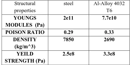
Structural properties
steel Al-Alloy 4032 T6 YOUNGS
MODULES (Pa)
2e11 7.7e10
POISON RATIO 0.29 0.33
DENSITY (kg/m^3)
7850 2690
YEILD STRENGTH (Pa)
2.5e8 3.3e8
International Journal of Advances in Engineering Research http://www.ijaer.com (IJAER) 2017, Vol. No. 13, Issue No. I, January e-ISSN: 2231-5152, p-ISSN: 2454-1796
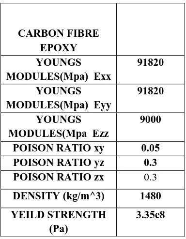
CARBON FIBRE EPOXY
Table 2: Properties of carbon fibre epoxy
Fig-7 Finite Element Model of Connecting Rod
RESULTS FOR EXSISTING MATERIAL (STEEL)
We apply same boundary conditions (10mpa) for all materials and results shown in below.
CARBON FIBRE EPOXY YOUNGS MODULES(Mpa) Exx
91820
YOUNGS MODULES(Mpa) Eyy
91820
YOUNGS MODULES(Mpa Ezz
9000
POISON RATIO xy 0.05
POISON RATIO yz 0.3
POISON RATIO zx 0.3
DENSITY (kg/m^3) 1480 YEILD STRENGTH
(Pa)
International Journal of Advances in Engineering Research http://www.ijaer.com (IJAER) 2017, Vol. No. 13, Issue No. I, January e-ISSN: 2231-5152, p-ISSN: 2454-1796
15
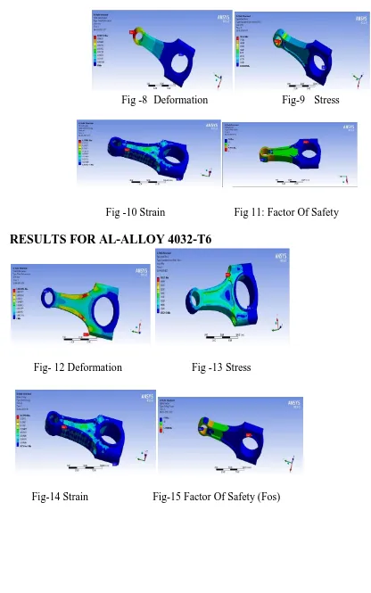
Fig -8 Deformation Fig-9 Stress
Fig -10 Strain Fig 11: Factor Of Safety
RESULTS FOR AL-ALLOY 4032-T6
Fig- 12 Deformation Fig -13 Stress
International Journal of Advances in Engineering Research http://www.ijaer.com (IJAER) 2017, Vol. No. 13, Issue No. I, January e-ISSN: 2231-5152, p-ISSN: 2454-1796
RESULTS FOR CARBON FIBRE EPOXY
Fig-16 Deformation Fig-17 Stress
Fig-18 Strain Fig -19 Factor Of Safety (Fos)
GRAPHS REPRESENTING THE COMPARISON OF THE RESULTS
Graph-1 Graph-2
Factor of safety
Graph-3
International Journal of Advances in Engineering Research http://www.ijaer.com (IJAER) 2017, Vol. No. 13, Issue No. I, January e-ISSN: 2231-5152, p-ISSN: 2454-1796
17
so our object is safe at this boundary condition, and finally safety factor values are high for carbon fibre and then al-4032 and then steel materials respectively.
THERMAL ANALYSIS
RESULTS FOR EXSISTING MATERIAL (STEEL)
Fig-20 Temperature Fig-21 Total heat flux
RESULT FOR AL-ALLOY 4032
Fig-22 Temperature Fig-23 Total heat flux
RESULT FOR CARBON FIBRE EPOXY
Fig-24 Temperature Fig-25 Total heat flux
International Journal of Advances in Engineering Research http://www.ijaer.com (IJAER) 2017, Vol. No. 13, Issue No. I, January e-ISSN: 2231-5152, p-ISSN: 2454-1796
THERMAL GRAPHS
Graph-7 Graph-8
FABRICATION OF DIE:
Raw material for Die:
The carbon fibre connecting rod was produced using hand-layer method.
Designing of Die:
The die is made in to three layers name as upper layer, middle layer and bottom layer. The middle which has hallow shape of cutting rod as shown in figure below will be the main die were material is changed in to desired shape with the help of epoxy resin. Other two layers are for covering the middle layer for not the air to pass and keep the resin at given higher temperature.
Fig-26 Middle plate of wooden piece
Die: The shape is cut at the given thickness of connecting rod with sharp and accurate shape in hollow form in the wooden part. This hollow form is formed for having a connecting rod in a definite form by filling the carbon fibre inside the hollow part of the wooden piece. After obtaining the shape of hollow part of connecting rod, the wooden piece is placed on the lower part by placing a polythene sheet in between the lower part and middle part.
International Journal of Advances in Engineering Research http://www.ijaer.com (IJAER) 2017, Vol. No. 13, Issue No. I, January e-ISSN: 2231-5152, p-ISSN: 2454-1796
19
Now after placing proper carbon fiber sheet with required epoxy resin the middle layer is covered with another polythene sheet and then top wooden layer of the die is place on the top and fixed firmly with nut and bolts in such a way that there is no passage of air in between the layer.
These total preparation is kept for 24 hours to get the desired shape connecting rod and should see that there is no loosing in nuts.
Fig-28
PRECAUTIONS
See that there is no leakage of epoxy from the passage of the die. Use clean brushes while applying epoxy in to the die.
Use gloves for applying epoxy in to the die. See that epoxy is not touched with bare hands.
After completing 24 hrs we see that total die was fixed with each other and to remove that we took help of hammer and chisel. After removing the upper and lower layer of the die polythene sheet is removed this was fixed on the surface of the middle layer.
As epoxy is highly adhesive the middle layer had to be broken to get the formed connecting of given thickness and shape. To do these we take help of hammer and hacksaw to make the wood into pieces. We use finishing tool to do finishing on the rod.
Finally we get the correct shaped connecting rod which is not having holes at both the ends to make these we use further process shown in next stage.
CONCLUSION
• From the results of structural analysis we can say that connecting rod made with carbon fiber
material shows good mechanical properties theoretically as compared to the presently used materials ie aluminum and steel.
• By thermal analysis we can say that carbon fiber withstand higher temperature as compared to other two and it has low heat flux. Theoretical values may vary.
International Journal of Advances in Engineering Research http://www.ijaer.com (IJAER) 2017, Vol. No. 13, Issue No. I, January e-ISSN: 2231-5152, p-ISSN: 2454-1796
Fig-29
FUTURE SCOPE IN THIS PROJECT
1. The uses of carbon fibre composites is expected to increase significantly during the next few years.
2.
There are requirements In EU’s end of Life Vehicles Directive (ELV) for the automotive industry to maintain a low ash content of residual products which can be achieved by replacing fibre glass with carbon fibre in composites. It can replace Aluminium in manufacturing of connecting rods for racing bikes as they can be replaced easily. Now a days most of the automobile companies are using carbon fibre for making only body parts.3.
By critically analyzing (manual testing) the project thermally, FUNTIONALLY GRADED MATERIALS can be introduced and fabricated for testing.REFERENCES
[1] Kuldeep B,Arun L.R, Mohammed Faheem“ANALYSIS AND OPTIMIZATION OF
CONNECTING ROD USING ALPHA SILICON CARBIDE COMPOSITES,” ISSN 2319- 8753 INTERNATIONAL JOURNAL of innvoative research in science, engineering and technology vol-2, issue-6, june 2013.
[2] GVSS Sharma and P Srinivas Rao “Process Capability Improvement of Engine Connecting Rod
machining process” journal of industrial engineering inter national 2013.
[3] Bhuptani K.M”structural analysis of bush bearing for small end connecting rod using
pro-mechanica” issn: 0975-668X vol2.
[4] Abhinav Gautam , k priya Ajit”static stress Analysis of Connecting Rod using FE approach” IOSR
journal of Mechanical and Civil Engineering(IOSR-JMCE) e-ISSN:2278-1684, p-ISSN:2320-334X, vol-10, issue 1( nov –dec 2013).
[5] P S Shenoy and A Fatemi, “Dynamic Analysis of Loads and Stresses in Connecting”, Proc.ImechE