An Efficient Routing Tree Algorithm for Combined Uplink
and Downlink Subframes on Centralized Scheduling in
IEEE 802.16 Based Wireless Mesh Networks
Ali Behfarnia, Vahid Tabataba Vakili
Department of Electrical Engineering, Iran University of Science and Technology, Tehran, Iran E-mail: [email protected], [email protected]
Received January 24, 2011; revised March 18, 2011; accepted March 20, 2011
Abstract
IEEE 802.16 mesh mode defines routing tree for transmitting data in centralized scheduling but it does not define any explicit proposal for combining uplink and downlink subframes. Deploying combined uplink and downlink subframes on the centralized scheduling scheme can be more flexible and utilization is improved. However, existing interferences among the transmission of neighboring nodes lead to performance reduction of the network. In this paper, an efficient routing tree algorithm is proposed with combined uplink and downlink slot allocation on the centralized scheduling scheme which can abate interferences in the network. This algorithm allows more subscriber stations to transmit concurrently and so improves spatial reuse in the network. Also, the algorithm uses multi-channel and single channel systems and considers relay model, smoothing switching frequently between transmitting and receiving in successive time slots and fairness in the network. Extensive simulation results demonstrate the effectiveness of the proposed method in terms of scheduling length, link concurrency ratio, network throughput and Channel Utilization Ratio (CUR).
Keywords: IEEE 802.16, Wireless Mesh Network, Centralized Scheduling, Slot Allocation, Routing Tree
1. Introduction
Wireless mesh network (WMN) is one of the attractive technologies to achieve better services in next generation wireless networks. The WMNs can be dynamically self-configured and self-organized, with the nodes within the mesh network automatically establishing and main-taining mesh connectivity among themselves. These fea-tures lead to advantages such as easy network mainte-nance, robustness, low up-front cost and reliable service coverage [1]. Also, the WMNs can be integrated with other networks such as IEEE 802.11, IEEE 802.16, ad hoc networks, cellular networks, etc.
Medium access control (MAC) layer in the IEEE 802.16 protocol stack supports two operation modes: PMP (point-to-multi-point) and mesh (multipoint-to- multipoint) [2]. All subscriber stations (SSs) in the PMP mode are managed by base station (BS) and each SS has to communicate with the BS before transmitting data to other SSs. In contrast, all mesh SSs (MSSs) within the network usually communicate with each other without coordinating with the mesh BS (MBS).
IEEE 802.16 mesh mode employs time division multi-ple access (TDMA) as the channel access method, where each radio channel includes multiple frames. A frame can be divided into time slots which can be assigned to each SS and the BS. There are two scheduling schemes for allocating these time slots to all SSs within the mesh network. One of them is centralized scheduling and the other is distributed scheduling. In the centralized scheme, all traffic is to or from the BS and so this scheme is pref-erable for transmitting internet traffic. All traffic will be transmitted between SSs in the distributed scheduling scheme and so this scheme is preferable for transmitting intranet traffic. In both centralized and distributed schemes, spatial reuse can be exploited for improvement of wire-less resource and network throughput. The spatial reuse in TDMA means that multiple links or nodes can transmit in a time slot simultaneously only if the transmissions do not lead to collision. In what fallows, we will focus on the centralized scheduling in IEEE 802.16 mesh mode.
model and constructing routing tree in centralized mode but did not consider downlink traffic and multi-channel system. Liu in [5] designed uniform slot allocation algo-rithms which exploit combined uplink and downlink slot allocation based on the centralized scheduling but did not consider an efficient routing algorithm and multi-channel system. Authors in [6,7] proposed centralized scheduling and channel assignment for IEEE 802.16 mesh networks but did not focus on downlink traffic and efficient rout-ing algorithm. Sheu in [8] proposed an interference- aware routing tree algorithm for the centralized schedul-ing but did not consider combined uplink and downlink traffic of each node and multi-channel system. Al- He-myari in [9,10] proposed a cross-layer design between network layer and MAC layer but did not discuss about the downlink parameters and combined uplink and down- link slot allocation.
In this paper, an efficient and interference-aware rout-ing tree algorithm is proposed which exploits combined uplink and downlink slot allocation on the centralized scheduling. The proposed method considers interferences, downlink packets, uplink packets and node identifier for determining parent nodes in routing tree construction. This algorithm can improve spatial reuse and network throughput. Multi-channel system is used to abate inter-ference from transmission of all neighboring nodes within the mesh network. In addition, this scheduling algorithm considers fairness among the nodes within the network and moderates switching frequently between transmitting and receiving in successive time slots. This algorithm is evaluated through some important metrics such as scheduling length, channel utilization ratio, net-work throughput and link concurrency ratio. To the best of authors’ knowledge, no research work has been pro-posed to address the routing tree method with consider-ing uplink and downlink traffic in combined uplink and downlink slot allocation on the centralized scheduling.
The rest of this paper is organized as follows. In sec-tion 2, we will introduce the system model in IEEE 802.16 mesh mode. In section 3, we will explain the proposed algorithm in detail. Section 4 shows the simu- lation results. Finally, the paper is concluded in section 5.
2. Basic Scheduling Scheme in IEEE 802.16
Mesh Mode
In this section, overview on frame structure of the IEEE 802.16 mesh mode and routing tree are introduced.
2.1. Frame Structure in IEEE 802.16 Mesh Mode
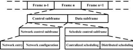
As mentioned above, each radio channel can be divided into frames. A frame consists of control subframe and
data subframe, as shown in Figure 1. Each control sub-frame is further divided into network control subsub-frame and schedule control subframe. The network control subframe creates and maintains the network by mesh network entry (MSH-NENT) message and mesh network configuration (MSH-NCFG) message. These messages are transmitted periodically in the mesh network. If the frame has not network control subframe, it has schedule control subframe. The schedule control subframe con-sists of centralized scheduling and distributed scheduling for sharing nodes within the network in a common radio resource. In centralized scheduling scheme, all SSs send their recourse requests to the BS by mesh centralized scheduling (MSH-CSCH) message. The BS receives these resource requests and determines flow assignments of all SSs. The SSs are informed about these assignments through MSH-CSCH. Another message is called mesh centralized scheduling configuration (MSH-CSCF). This message is broadcasted by the BS to disseminate infor-mation about routing tree and whole centralized sched-uling configuration among all SSs within the mesh net-work. The distributed scheduling scheme can be classi-fied into coordinated and uncoordinated. Each SS in the coordinated distributed scheduling must coordinate itself by its two hops neighbor for a collision free data trans-mission. But, schedules are determined by directed re-quests and grants between each two SS in uncoordinated distributed (like ad-hoc networks). Both coordinated and uncoordinated schemes employ mesh distributed sched-uling (MSH-DSCH) message to convey resource re-quests and grants to the neighbors [2].
2.2. Routing Tree
[image:2.595.309.533.620.705.2]To construct the routing tree, if a new station wants to join the mesh network, it must scan the MSH-NCFG message to synchronize with the network. Then, the new station selects a parent node among all possible neigh- bors according to specific policy (which will be dis-cussed in next section). After that, the new station trans-mits a MSH-NENT message with registration informa-tion to the MBS via its parent node. After receiving the registration message of new station, the MBS adds the new station to the network as a child of determined parent
node.
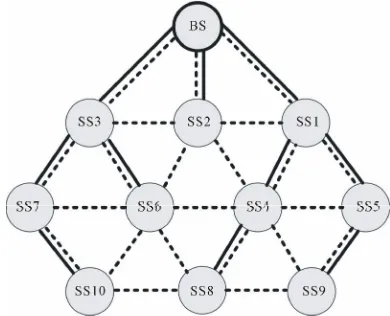
In the routing tree construction procedure, the hop- count of the MBS is assumed to be zero and all neigh-bors of MBS are assigned to be one. A station selects its parent node based on smallest hop-count and then hop-count of it is assigned to be its parent node plus one. Figure 2(a) gives an example of mesh topology and routing tree, where the dashed lines show the mesh to-pology and the solid lines represent the routing tree.
3. Proposed Algorithm
3.1. Motivation and Problem Overview
Several issues can be considered concerning the central-ized scheduling scheme. The issues can be categorcentral-ized in three parts:
• Routing tree: The policy of routing tree construc-tion influences on system performance.
• Resource management: resource requests from all SSs must be managed by the BS. Also, the BS must determine the uplink and downlink flow as-signments in such a way that overload does not occur in the network.
• Scheduling algorithm: all SSs should be scheduled without interferences to achieve higher spatial re-use and network throughput in the mesh network. In this work, we will focus on the routing tree and scheduling algorithm. Resource management is assumed to be known in the proposed method. In the other words, we first design a routing algorithm and then schedule the minislots of data subframe according to the routing tree.
This work can be called the routing and packet sched-uling (RPS), which has become an important issue in the centralized scheduling. To illustrate the issue more clearly, let us consider the example of routing tree in Figure 2(a). A single channel time division duplex model is assumed to be adopted in this network and each SS is assumed has only one packet for uplink transmission and one packet for downlink transmission (homogeneous). Figures 2(b)-(c) represents the scheduling matrix (SM) which is based on routing tree shown in Figure2(a). The terms 1♦ and 1● which are shown in the SM are used for transmitting downlink and uplink traffic, respectively. Among several criteria to select the nodes for sending packets, we select the least hop-count to the BS for up-link transmissions and largest hop-count from the BS for downlink transmission, because these selections are demonstrated to be the best in [4,5]. Also, we can find from the [5] that for combined uplink and downlink slot allocation (CSLA), the downlink slot allocation is im-plemented first and then followed by uplink slot alloca-tion. Thus, it is adopted in our example. As we see from
the Figures 2(b)-(c), the node SS10 which with the largest hop-count from the BS and largest identifier is transmit-ted first by the BS. In this condition, nodes SS1and SS3 cannot transmit and receive. Also SS4 and SS6 cannot transmit with considering interference model. The SS8 can transmit its uplink traffic to SS4 without interference at the first time slot. If all nodes that are not interfered with each other have ended their transmissions at a time slot, the scheduling of that time slot is finished. Thus,
(a)
(b)
(c)
scheduling the first time slot is finished. In the next time slot, node SS2 forwards the downlink traffic of SS10 to the SS6. In this condition, with considering the interfer-ence model, nodes SS1, SS3 and SS4 cannot receive the traffic from other nodes and SS3, SS4, SS7, SS8 and SS10 cannot transmit to other nodes. Thus only link SS2- SS6 is scheduled in this time slot. With the same proce-dure, scheduling matrix is constructed in the Figures 2(b)-(c), where 30 time slot is required to transmit the traffic of all nodes to their destinations.
Constructing efficient routing tree algorithm for al-lowing more nodes to transmit simultaneously at a time slot is the goal of this paper. With considering the con-struction of routing tree in the network layer and sched-uling algorithm in the MAC layer, the cross layer con-cept can be formed in our mind. In the network layer, all information about routes and interferences of the nodes within the network are acquired from BS. In the MAC layer, all centralized scheduling information is sent to the routing tree algorithm in network layer. After establish-ing the routes of the nodes, the paths of routestablish-ing tree are fed to the MAC layer. With considering the channel as-signment of multi-channel system in the MAC layer and implementing centralized scheduling, we can achieve the reduction of interferences in the network.
3.2. Interference Model and Channel Assignment
There are two types of interferences in the wireless net-works in which the nodes use a shared medium to com-municate with each other. The first type is called primary interference which occurs when a station has to transmit or receive at one time. The other type is called secondary interference which occurs when a station M who intends to receive from station N is within the range of another transmitter whose transmissions, though not intended for M, interfere with the transmissions of N.
For the single channel single transceiver mode, the following interference model is assumed in the mesh network:
• Each node’s radio is assumed half duplex, and so nodes cannot receive and transmit in one time. Al-so, all nodes cannot receive from multiple nodes or transmit to multiple nodes in one time.
• All nodes in the range of the transmitter except re-ceiver cannot receive from other nodes and all nodes in the range of receiver except transmitter cannot transmit, because interference occurs in these conditions.
In respect to the use of single transceiver for each node in the network, the primary interference cannot be eliminated. However, by using multi-channel single
trans-ceiver system each node can employ one channel at each time slot, and also can employ other channel in the other time slots. Thus, different stations can use different chan- nel in a time slot and so a lot of nodes can transmit/receive simultaneously. Hence, with exploiting multi-channel system the secondary interferences can be eliminated.
For illustrating the channel assignment of the multi- channel system more lucidly, we can return to the sched-uling matrix and routing tree which are shown in Figure 2. According to use of the single channel system and single transceiver, in the second time slot of the schedul-ing matrix, only SS2 can transmit its packets to SS6. However, if the multi-channel system was used in this network with the same condition, the link BS-SS3 would be activated for downlink transmission and also link SS5-SS1 and SS9-SS4 would be activated for uplink transmission.
3.3. Proposed Routing Tree Algorithm Common
The goal of our routing algorithm is to find the best paths between the static SSs and the BS in the routing tree to-pology. In this algorithm four parameters are considered; number of hop-count from the BS, node identification (i.e. ID node), number of interfering nodes and the num-ber of uplink and downlink traffic per each node. The proposed algorithm is implemented based on the follow-ing steps:
1) Select the parent node based on the least hop-count from the BS.
2) If there is one node in the transmission range, choose it as the parent node, else go to step 3. 3) Calculate the number of neighboring nodes that
lead to interference from the selected nodes and then choose the parent nodes with the least number of interference.
4) If there is one node with the least number of inter- ference, choose it as the parent node, else go to step. 5) Calculate the load of the routes which include the
candidate parent nodes. This parameter can be ob- tained as summation of all uplink packets and down- link packets of the nodes along the route to the BS. After that, choose the parent node in the path with the minimum load.
6) If there is one path, choose corresponding parent node, else go to step 7.
algorithm can be implemented as follows. SS1, SS2 and SS3 have one upper layer station and so they choose it as their parent node. SS4 can select SS1 and SS2 as its par-ent node and so the algorithm will par-enter to the third step. With considering the interference number of candidate nodes, SS4 selects SS1 as its parent node. SS5 has only one upper level node and so it will select SS1 as the par-ent node. SS6 and SS7 select SS3 as their parpar-ent node with the similar reasons of SS4 and SS5. SS8 has SS4 and SS6 in its upper layer. These two stations have same condition in interference number and so the proposed algorithm will enter to the step 5. But, these two parent nodes have similar value in their load of routing paths which are equal to 4 (2 uplink packets plus 2 downlink packets). In this condition, the algorithm will enter to the step 7 and so SS8 select SS4 as its parent node. SS9 se-lect SS5 between SS5 and SS4 as the parent node be-cause the interference number of SS5 is lower than SS4. With the same reason SS10 chooses SS7 as its parent node. Figure3 shows the proposed routing tree by the solid lines.
3.4. Centralized Scheduling Scheme
From the resource management, all SSs and the BS are assigned service token (ST) based on their uplink and downlink traffic demands. The ST which is assigned to each SS for uplink or downlink (at the BS) demands can be obtained as its traffic demands divided by greatest common divisor of all SSs traffic demands. For example, if traffic demands of SSs are 2 Mbps, 4 Mbps, 6 Mbps and 10 Mbps, the STs which are assigned to SSs will be 1, 2, 3 and 5, respectively. With this assignment, the fairness can be guaranteed because the nodes within the network will not be starved. Downlink service token ma-trix (DSTM) and uplink service token mama-trix (USTM) can be constructed from downlink and uplink ST de-mands of all nodes.
Figure 3. The proposed routing tree algorithm.
The link selection criterion for implementing the slot allocation algorithm is adapted to the CSLA method which is discussed in [5]. Therefore, we select the least hop-count to BS for uplink transmissions and largest hop-count from the BS for downlink transmission. Also, downlink slot allocation has higher priority than uplink slot allocation in each time slot. In each link selection process, transmit node (T_n), receive node (R_n) and source node (S_n) of each link are obtained. The S_n refers to the source node of ST and the T_n and R_n are relay nodes in the route between S_n and its destination.
After each slot allocation, the corresponding matrixes will be adjusted and SM will be set. Setting the SM is as follows:
SM (T_n, k) = S_n (1) Also, adjusting the DSTM and USTM are as follow:
[image:5.595.73.268.546.704.2]DSTM (T_n, S_n) = DSTM (T_n, S_n) – 1 (2) DSTM (R_n, S_n) = DSTM (R_n, S_n) + 1 (3) USTM (T_n, S_n) = USTM (T_n, S_n) – 1 (4) USTM (R_n, S_n) = USTM (R_n, S_n) + 1 (5) Relation (1) means that T_n is scheduled at time slot k in the SM. The service token of corresponding S_n at the transmitter is diminished by one, and the service token of corresponding S_n at the receiver is increased by one, as in (2) and (3). Likewise, the USTM will be adjusted sim-ilar to DSTM, as in (4) and (5). In this algorithm, the first input first output (FIFO) is assumed as the buffer of each node. Also, each receiving node forwards the traffic after receiving all the traffic from its transmitter node. In the other words, each receiving node collects all ST of its transmitter and then transmits the traffic. This procedure leads to reduce switching frequently between transmit-ting and receiving nodes in successive time slots. For more information about switching frequently between receiving and transmitting within two adjacent time slots, we refer interested readers to [5].
Figure 4 gives the SM in accordance with the pro-posed routing tree algorithm which is shown in Figure3. Figure 4(a) gives the SM with using single channel sys-tem and Figure 4(b) gives the SM with using multi- channel system. In these SMs, we assume that the value of ST for each node in uplink and downlink direction is to be one (homogeneous). As we see from these figures, we can find that 23 and 20 time slots are required to con-vey the traffic of all nodes to their destinations which is less than traditional structure which is shown in Figure2.
4. Simulation
4.1. Performance Metrics
(a)
(b)
Figure 4. Scheduling matrixes of the proposed algorithm with using (a) single channel system and (b) multi-channel system.
through scheduling length, normalized network throughput, channel utilization ratio (CUR) and link concurrency ratio (LCR). The scheduling length is the number of time slots which is required to transmit the traffic of all SSs and the BS to their destinations in a cycle. The cycle of a link scheduling is the time needed to transmit all the data traffic under certain traffic model in the WMN. The scheduling length is one of the preva-lent criteria in the scheduling algorithm which is consid-ered in most of existing literature. Normalized network throughput is employed for evaluating the network per-formance which can be calculated as the total number of STs of all nodes divided by scheduling length. The CUR can be obtained as the number of occupied time slots in SM divided by number of all possible time slots. All possible time slots can be obtained as the scheduling length multiplied by the number of nodes. Transport ca-pacity of the mesh network can be improved via higher CUR. The LCR is the average number of nodes that can transmit data simultaneously at a time slot. This parame-ter is employed for evaluating the spatial reuse efficiency in the mesh network.
4.2. Simulation Setup
We compare the proposed algorithm with the CSLA me-thod in [5] which is proposed for combining uplink and downlink slot allocation in the centralized scheduling. Also, the results compare with uplink and downlink slot allocation which are executed separately.
We use C programming language to evaluate the per-formance of the proposed algorithm. A square area of size 50 by 50 units is used for distributing all SSs in the mesh network randomly and uniformly. The BS is lo-cated on the center of the square area. A same transmis-sion range is assumed for all SSs and the BS. Two sta-tions will be neighbors if the distance between them is smaller than their transmission range. The transmission range of each node is assumed to be 10 units. The service token number of the nodes is randomly selected between 0 and 5 (heterogeneous) and 1 (homogeneous). Simula-tions are implemented for the range of nodes from 20 to 100 with increment step of 10. Results presented in this section are averaged among 500 connected graphs.
4.3. Simulation Results
Figures 5-8 gives the scheduling length, channel utiliza-tion ratio, link concurrency ratio and normalized network throughput. The meaning of proposed-sig and pro-posed-mul that are used in these figures refer to use of single channel and multi-channel systems with the pro-posed algorithm.
As we see from the Figure 5, the scheduling length increases with the number of nodes because with in-creasing the nodes in the network, the traffic demand is also increased. Moreover, we can find that with use of multi-channel system the scheduling length is signifi-cantly improve, and this is because with employing mul-ti-channel system more subscriber stations can transmit simultaneously.
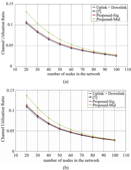
From the Figure 6, we can observe that increasing the number of nodes lead to decrease the CUR because with increasing the nodes, interfering nodes is also increased. Also, with exploiting multi-channel system in the algo-rithm the CUR can significantly improve in compare to use of single channel system. The reason is due to use of same channel at the same time slots which lead to incre-ment the interferences which are sorely affected on si-multaneous transmission. Moreover, we can find that the CUR is usually below 10% for the number of nodes more than 20 because the nodes which are at the first hop-count from the BS act as bottlenecks in compare to the nodes with higher number of hop-count which idle in most of the time.
(a)
[image:7.595.63.282.75.367.2](b)
Figure 5. Scheduling length. (a) Service token of all nodes
0,5 ; (b) Service token of all nodes = 1.
(a)
(b)
Figure 6. Channel utilization ratio. (a) Service token of all nodes
0,5 ; (b) Service token of all nodes = 1.(a)
[image:7.595.321.533.75.363.2](b)
Figure 7. Link concurrency ratio. (a) Service token of all nodes
0,5 ;(b) Service token of all nodes = 1.(a)
(b)
[image:7.595.319.523.405.690.2] [image:7.595.63.280.410.690.2]Figure 8 shows the normalized network throughput. The figure represents that the proposed algorithm with using multi-channel system is higher throughput than single channel and the proposed algorithm is better than CSLA algorithm which is discussed in [5]. The uplink plus downlink is the worst performance among the schemes because this scheme deprives of exploiting combined uplink and downlink transmissions and so the spatial reuse is lower than other schemes. As expected in Figure6, Figure 7 and Figure8, ST does not influence on the CUR, LCR and normalized network throughput so much, because ST cannot independently influence on these metrics.
5. Conclusions
An efficient routing tree algorithm is proposed for com-bined uplink and downlink slot allocation on the central-ized scheduling scheme in IEEE 802.16 based wireless mesh networks. This algorithm considers interferences, downlink packets, uplink packets and node identifier for determining parent node in the routing tree construction. This algorithm can reduce interference among the nodes and improve spatial reuse in the network. Also, some related issues such as fairness, relay model, slot reuse and moderating switching frequently between transmit-ting and receiving in the successive time slots have been considered. This work is compared with combined up-link and downup-link slot allocation (CSLA) that is pro-posed in [5]. Results confirm that the propro-posed algorithm can significantly increase the link concurrency ratio, network throughput and channel utilization ratio as well as reducing the scheduling length. In conclusion, the presented algorithm will provide a simple routing algo-rithm for combined uplink and downlink slot allocation on the centralized scheduling in IEEE 802.16 mesh mode.
6. References
[1] I. F. Akyildiz, X. Wang and W. Wang, “Wireless Mesh Networks: A Survey,” Elsevier Journal of Computer Net- works, Vol. 47, No. 4, March 2005, pp. 445-487.
[2] IEEE Standard 802.16-2004, “Local and Metropolitan Area Networks—Part 16: Air Interface for Fixed Broad- band Wireless Access Systems,” October 2004.
[3] B. Han, F. P. Tso, L. Lin and W. Jia, “Performance Eva- luation of Scheduling in IEEE 802.16 Based Wireless Mesh Networks,” Proceedings of International Conference on Mobile Adhoc and Sensor Systems, Vancouver, 9-12
October 2006, pp. 789-794.
doi:10.1109/MOBHOC.2006.278652
[4] B. Han, W. J. Jia and L. D. Lin, “Performance Evaluation of Scheduling in IEEE 802.16 Based Wireless Mesh Networks,” Elsevier Journal of Computer Communications,
Vol. 30, No. 4, February 2007, pp. 782-792.
[5] S. Liu, S. Feng, W. Ye and H. Zhuang, “Slot Allocation Algorithms in Centralized Scheduling Scheme for IEEE 802.16 Based Wireless Mesh Networks,” Elsevier Jour- nal of Computer Communications, Vol. 32, No. 5, March
2009, pp. 943-953.
[6] Y. Tang, Y. Yao and J. Yu, “A Novel Joint Centralized Scheduling and Channel Assignment Scheme for IEEE 802.16 Mesh Networks,” Proceedings of 4th Interna- tional Conference on Computer Science & Education,
Nanning, 25-28 July 2009, pp. 289-293.
[7] P. Du, W. Jia, L. Huang and W. Lu, “Centralized Sche- duling and Channel Assignment in Multi-Channel Single- Transceiver WiMax Mesh Network,” Proceedings ofIEEE Wireless Com- munications and Networking Conference,
Hong Kong, 11-15 March 2007, pp. 1734-1739.
[8] P. R. Sheu, C. F. Hu, C. C. Liou, F. C. Chuang and Y. C. Chen, “An Efficient and Interference-Aware Centralized Routing Tree Algorithm for the Routing and Packet Scheduling Problem in IEEE 802.16 Mesh Networks,”
Proceedings ofInternational Conference on Communica- tion and Mobile Computing,Shenzhen, 12-14 April 2010,
pp. 496-503.doi:10.1109/CMC.2010.340
[9] A. Al-Hemyari, C. K. Ng, N. K. Noordin, A. Ismail and S. Khatun, “Cross Layer Design in 802.16d,” Australian Journal of Basic and Applied Sciences, Vol. 3, No. 3,
2009, pp. 1591-1600.
[10] A. Al-Hemyari, C. K. Ng, N. K. Noordin, A. Ismail and S. Khatun, “Constructing Routing Tree for Centralized Sche- duling Using Multi-Channel Single Transceiver System in 802.16 Mesh Mode,” Proceedings of IEEE Internatinal Conference on RF and Microwave, Kuala Lumpur, 2-4