functions.
CLARK, Anthony <http://orcid.org/0000-0003-3167-0739>
Available from Sheffield Hallam University Research Archive (SHURA) at:
http://shura.shu.ac.uk/11931/
This document is the author deposited version. You are advised to consult the
publisher's version if you wish to cite from it.
Published version
CLARK, Anthony (2000). Object-oriented refinement and proof using behaviour
functions. In: Rigorous Object-Oriented Methods 2000, York, 1 January 2000. BCS
Electronic Workshops in Computing.
Copyright and re-use policy
See
http://shura.shu.ac.uk/information.html
Sheffield Hallam University Research Archive
Tony Clark
Department of Computing, University of Bradford West Yorkshire, BD7 1DP, UK
Abstract
This paper proposes a new calculus for expressing the behaviour of object-oriented systems. The semantics of the calculus is given in terms of operators from computational category theory. The calculus aims to span the gulf between abstract specification and concrete implementation of object-oriented systems using mathematically verifiable properties and transformations. The calculus is compositional and can be used to express the behaviour of partial system views. The calculus is used to specify, analyse and refine a simple case study.
1
Introduction
In [Gog75], [Ehr91] and [Gog90] Goguen et al. propose an abstract model of object systems based on standard con-structions in Category Theory. They show how to use the concon-structions to build systems but do not propose a calculus for expressing and reasoning about them. In [Cla99a], [Cla99b] and [Cla99c] a calculus is proposed for expressing object systems based on Goguen’s work. The calculus was shown to support incremental system development based on features of Computational Category Theory [Ryd88]. The calculus does not have a formal semantics and therefore its link to the abstract object model is weak.
This paper develops a formal semantics for the
o-calculus. The semantics encodes the required categorical constructions as builtin operators and then uses them to express a number of features of object-oriented systems development including: (under-)specification; refinement; encapsulation; invariant properties.
This work contributes to the area of object-oriented systems development by providing a rigorous framework within which aspects of development can be defined and explored. In particular the
o-calculus aims to span the gulf between abstract specification and concrete implementation using mathematically verifiable refinement transforma-tions. The
o-calculus can express partial views of a system and is therefore suitable as the basis for a semantics of UML [UML98] and as such can be seen as an extension of, or complimentary to, [Cla97] [Eva98] [Eva99] and [Lan98].
The builtin operators of the
o-calculus arise from Computational Category Theory. The reader is directed to [Bar90], [Ryd88] and [Gog89] for definitions of the appropriate constructs and to [Cla99a] for a discussion of how these constructs are used in the development of object-oriented systems.
This work differs from other approaches with similar aims. The Object Calculus [Bic97] uses similar categorical constructs but uses a logic rather than a-calculus to express models. Following Goguen, we propose that the be-haviour of a system is a limit on a diagram of bebe-haviours; diagrams are also used in [Ken99] [Ken97] where the aim is to express logical properties of data. Other calculi have been proposed as the basis for object-oriented systems, notably those defined in [Aba98]. The
o-calculus differs from other calculi in that it can express partial views of a system, incorporates non-determinism, solve constraints via equalizers and has a builtin notion of refinement via refinement morphisms.
The paper is structured as follows: section 2 gives an overview of the semantic model used for object-oriented systems; section 3 defines the
that is used to demonstrate features of object-oriented system development using the
o-calculus in the rest of the paper; section 5 shows how a system invariant is verified; section 6 shows how mutual constraints can be achieved by composing sub-systems; section 7 shows how object-oriented encapsulation can be achieved using the refinement; finally sections 8 and 9 show how refinement achieves concrete data representation and an implementation in Java.
2
Behavioural Object-Oriented Model
Systems are constructed as a collection of objects. Each object is a separate computational system with its own state modified in response to handling messages. A message is a package of information sent from one object to another.
The computation performed when a message is handled by an object depends on the object’s current state and causes the object to change state and produce output messages. If we observed an object over a period of time we would see a sequence of messages and state changes::::
1 (I1;O1)
7;! 2
(I2;O2) 7;!
3
:::where each
jis an object state, I
j are input messages, and O
j are output messages. Such a sequence is an object calculation and describes a single object in state
jreceiving messages I
jcausing a state change to
j+1and producing output messages O
j.
A message consists of a source object, a target object and some message data. The source and target objects are identified by their object identity tags. For a given object system, the data items which can be passed as messages will be defined for each type of target object. A message, whether input or output, is represented as(t
1 ;t
2
;v)where t
1 identifies the source object, t
2identifies the target object and
v is the message data. Where any of the message components may be inferred from context they are elided.
Object systems are constructed from multiple objects interacting by passing messages. The state of an object system is a set of object statesS. Computation in an object system occurs when the messages in setI are sent to the objects inSproducing a new set of object statesS
0
and a collection of output messagesO::::7;!S (I;O)
7;! S 0
7;!::: Object-oriented designs represent non-deterministic computational systems. Object calculations are represented as a
calculation graph where the nodes of the graph are labelled with sets of states and the edges are labelled with pairs of
input and output message sets.
Object system calculations can be transformed by graph homomorphisms. Such transformations can be used as the basis of system composition operations based on graph products and coproducts. Equalizers can be used to constructively find equivalence proofs expressed in terms of graph homomorphisms. The behaviour of a system is expressed as a limit on a diagram consisting of calculation graphs and graph homomorphisms. System properties can be expressed by adding the required behaviour to the diagram and then showing that the limit is preserved.
The rest of this paper uses these features as the semantic basis of a calculus for expressing, verifying and trans-forming object-oriented system designs.
3
The
o
-Calculus
The
o-calculus is a notation for expressing object-oriented system designs. It is a standard normal order
-calculus [Han94] [Plo75] extended with builtin operators [Lan64] for constructing behaviour functions in terms of behaviour products, coproducts, equalizers and morphisms.
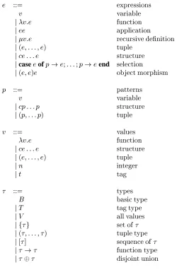
The syntax of the
o-calculus is given in figure 1. The semantics of the basic calculus is given as a convertibility relation between terms in appendix A. All
o-terms have a type given by the type theory defined in appendix A. The following sugare
1whererec v=e
2is translated as (v:e
1 )(v:e
2
). The following sugar casee 1of
::: elsee 2end is translated as casee
1of
::: v!e 2end.
3.1
Object Calculations and Morphisms
An object calculation is a sequence of object state transitions caused as a result of a collection of objects receiving messages, changing state and sending messages. Given an object with identityt, statevand behavioure, if the object receives messagesI, changes state and behaviour tov
0 ande
0
, and produces output messagesO thenef(t;v)gI = (e
0 f(t;v
e
::=
expressions
v
variable
j
v:e
function
j
ee
application
j
v:e
recursive denition
j(
e;:::;e
)
tuple
j
ce:::e
structure
jcasee
ofp
!e
;
:::
;
p
!e
endselection
j
(
e;e
)
e
object morphism
p
::=
patterns
v
variable
j
cp:::p
structure
j(
p;:::p
)
tuple
v
::=
values
v:e
function
j
ce:::e
structure
j(
e;:::;e
)
tuple
j
n
integer
j
t
tag
::=
types
B
basic type
j
T
tag type
j
V
all values
jf
gset of
[image:4.612.181.431.59.448.2]j
(
;:::;
)
tuple type
j[
]
sequence of
j !function type
jdisjoint union
Figure 1: Syntax of
o
e
f(
t;v
)
gI
= (
e
0S;O
)
e
f(
t;
env
e v
)
g [(I;O
)]7;!
e
0S
e S
[] 7;!e S
e
1S
1m
1 7;!e
2
S
2e
2S
2m
2 7;!e
3
S
3e
1S
1m
1+ +
m
2 7;!
e
3
S
3e
1S
1m
7;!e
2
S
2e
3(
1(
S
2))
2(m
)7;!
e
4
(
1(
S
2))
8S
1
;m
(
1;
2)
e
1=
e
3e 1
S 1
m
7;!e0 1 S 0 1 e 2 S 2
m
7;!e0 2 S 0 2
(coprod
e 1 e 2)(
S 1 S 2)
m
7;!
(coprod
e 0 1 e 0 2 ;S 0 1 S 0 2)
e 1 S 1m
1 7;!e0 1 S 0 1 e 2 S 2
m
2 7;!e0 2 S 0 2 `S 1 S 2 ;`S
0 1 S 0 2
(prod
e 1 e 2)(
S 1 S 2)
zipm
1m
27;!
(prod
e 0 1 e 0 2 ;S 0 1 S 0 2)
(
e2
) =
e1
(
1)
e 2= (
2
)
e 2eq
e 1 1 2= (
e 2
[image:5.612.189.422.61.228.2];
)
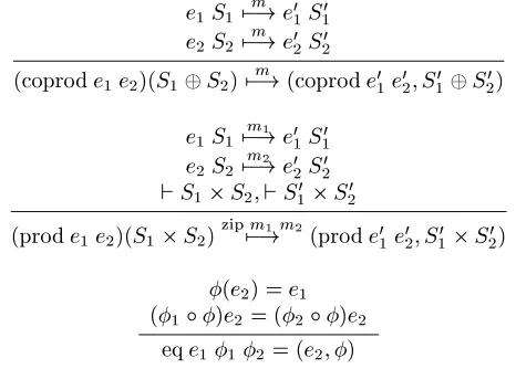
Figure 3: System Construction Operators
A pre-system behaviour, of typeP is a function that expects to be supplied with a set of states. The result is a system behaviour of typeO that expects a set of input messages and produces a replacement system behaviour and a set of output messages. A system state of type
is either a single object state or a pair of system states. A systemmessage of typeMis either a set of object messages or a pair of system messages. System behaviour types are defined below:
P
=
fg!(
O;M)
O=
M!(
O;M)
= (
T;V)
(
;)
M=
f(
T;T;V)
g(
M;M)
Object calculations are represented by the transition relation7;!which is defined in figure 2. Each transition is labelled with sequences of trees of input output messages. The operator env associates all atomic state values with a name relative to a given behaviour function, the result is a partial functionfrom names to values. An object calculationeS
m
7;!e0 S
0
is well formed when all output messages produced by each transition are input messages in the next transition.
Object calculation morphisms are pairs of functions
(
1;
2
)
such that1is a mapping between object states and
2is a mapping between sequences of input output messages. Such a morphism can be applied to a behaviour function ein
o
to produce a new function(
1 ;
2
)
ewhose behaviour is given in terms of a mapping one-calculations as shown in figure 2. Composition of object calculation morphisms is defined component-wise as follows:
(
1 ; 2
)
(
3 ;4
) =
(
1 3 ; 24
)
. The type of a calculation morphism is= (
f
g!fg;[
M]
![
M])
.3.2
Constructing Systems
The state of a system of objects is a set of binary trees. The leaves of each tree are labelled with object states. Views of the same object may occur at different leaves in the tree providing that they are consistent. A system stateS is consistent` S when it is a set of possible states for the same objectt: `
S
i
=1;n
f
(
t;i
)
g, when it is the composition of two different object states: `S
i
=1;n
f
(
t 1;
i
)
g Sj
=1;m
f(
t2
;
j
)
gsuch thatt 16
=
t2, when it is the composition of two views of the same object such that attribute names occurring in both have the same values:
` S
i
=1;n
f
(
t;i
)
g Sj
=1;m
f
(
t;j
)
gwheni
(
n) =
j
(
n)
for alli;j;n 2dom(
i
)
\dom(
j
)
, and finally when pair-wise decomposition of the state is well defined:`S1 S 2 S 3when `S 1 S 2, `S 1 S 3and `S 2 S 3. Systems are constructed from objects using the operators
:
O!O!(
O;;)
,+ :
O!O!(
O;;)
andis used to express system constraints. System construction is defined using the operators in figure 3 whereis disjoint set union and zip merges pairs of sequences to produce sequences of pairs. The operatorsprod :
O
!O
!O
and coprod:O
!O
!O
are used to construct products and coproducts consisting of behaviour functions and associated behaviour morphisms. They are defined by extending theo
-convertibility relation as follows: 1 (prode
1
e
2 )=e
1
2 (prode
1
e
2 )=e
2
e
1e
2
=(prod
e
1
e
2;
1;
2 ) 1e
1=coprod
e
1e
2 2e
2=coprod
e
1e
2e
1 +e
2
=(coprod
e
1
e
2;
1;
2 )The theory
o
is extended with equivalences for the underlying operators prod, coprod and eq. In each case a one step transition defines term equivalence, for example:(prod
e
1e
2)
S
[(I;O
)]7;!
e
3S
0 prod
e
1
e
2S I
=(e
3
S
0;O
)
Products and coproducts must observe some simple algebraic properties given in the following theorems.
Theorem 1 Let
e
t
(t
)be a terminal object behaviour defined:e
t
(t
)()(I
) =(e
t
(t
)();
;). Then,e
e
t
(t
) =e
=e
t
(t
)e
.The following proof shows that there exists an isomorphism between
e
ande
e
t
(t
)(and equivalentlye
ande
t
(t
)e
). Define an object morphism(1
;
2 )as: (1
;
2):
e
e
t
(t
)!e
1([f(
i
;
(t;
))g)=[fi
g 2 (m
)=8 < :
[] when
m
=[][(
I;O
)] whenm
=[((I;O
);
(fg;
;)] 2 (m
1 )++ 2 (m
2) when
m
=m
1++
m
2 The inverse(;1 1
;
;1 2
):
e
!e
e
t
(t
)is well defined and therefore:( ;1 1;
;2 2
)(
1;
2)=Id
e
and( 1;
2) (
;1 1;
;1 2)=Id
e
e
t(t
). A similar argument is used to show thate
e
t
(t
)is isomorphic toe
t
(t
)e
. QED. Theorem 2 System composition is associative, i.e.(e
1
e
2 )
e
3 =
e
1 (e
2e
3 )The following proof sketch shows that the required isomorphism exists. Firstly define an object morphism(
1;
2): (
e
1
e
2 )
e
3 !
e
1 (e
2e
3 ): 1 ([f((v
1
;v
2 );v
3
)g)=[f(
v
1;
(
v
2;v
3))g
2 (m
)=8 < :
[] when
m
=[][(
p
1;
(
p
2;p
3))] when
m
=[((p
1;p
2)
;p
3 )] 2 (m
1 )++ 2 (m
2) when
m
=m
1++
m
2 It is straightforward to define(;1 1
;
;1 2
). QED.
Theorem 3 The system construction operatordistributes over+, i.e.
e
1(
e
2+
e
3)=(
e
1e
2)+(
e
1e
3). The following proof uses the transition semantics of both sides of the equation to show that they are equivalent. From
e
1S
1m
1 7;!e
0 1
S
0 1,
e
2
S
2m
2 7;!e
0 2
S
0 2and
e
3
S
3m
2 7;!e
0 3
S
0
3we get the following: (
e
1 (e
2 +e
3 ))(S
1 (S
2S
3 )) zipm
1m
2 7;! (e
0 1 (e
0 2 +e
0 3 ))(S
0 1 (S
0 2S
0 3 )) ((e
1e
2 )+(e
1
e
3 ))((S
1S
2 )(S
1
S
3 ))
zip
m
1m
2 7;! ((e
0 1e
0 2)+(
e
0 1e
0 3 ))((S
0 1S
0 2)(
S
0 1S
0 3 ))3.3
System Refinement
System development through step-wise refinement is attractive since it allows abstract models to be developed early in the life-cycle and then refined to concrete implementations through a series of verified transformations. Consider two behaviour functions
e
1 ande
2such thate
2is a more concrete version ofe
1. Typically, the states ofe
2 will be related to those ofe
1but will involve more components and inter-relationships. For example, object-oriented design promotes the use of encapsulation whereby structured data is implemented as a collection of objects whose detail is hidden behind method interfaces. The calculations ofe
1will be more abstract than those ofe
2;e
1may perform complex tasks in a single computation step wherease
2must observe implementation constraints imposed by the target system.If
e
1is an abstract version of the required system behaviour ande
2is a (relatively) concrete version thene
2must do everything thate
1can do subject to an appropriate transformation on states and calculations. Furthermore, ife
1is complete thene
2must not introduce any behaviour that is inconsistent with that defined bye
1.A behaviour refinement from
e
1 toe
2 is a pair of mappings (1;
2 ) :e
1 !
e
2 such that for every abstract calculation:
e
1S
1m
7;!e
0 1
S
0
1there exists a concrete calculation:
e
2S
2 2 (m
) 7;!e
0 2
S
2 such that
1 (S
2 ) =
S
1 and
1 (S
0 2
)=
S
0 1. Theorem 4 If(1
;
2 ):e
1 !
e
2and (
0 1
;
0 2
):
e
2!
e
3are two refinements, then (
1
0 1
;
0 2
2 ):
e
1 !
e
3is also a refinement.
Theorem 5 If(
1;
2):
e
1!
e
2is a refinement then (
1
;
2)Id
e
:e
1e
!e
2e
is also a refinement.3.4
Message Passing
Computation occurs in an object-oriented system in terms of message passing. A behaviour is expressed in the design notation as a function which maps incoming messages to a pair(
e S;O
)wheree S
is a replacement behaviour andO
is a set of outgoing messages. Once the messagesO
have been produced, the behaviour is immediately ready to handle new incoming messages as specified bye
.The basic model of message handling is therefore asynchronous. This decision arises because object-oriented design notations can express both synchronous and asynchronous message passing. Typically there are different notations to express send message and wait for reply and send message without waiting for reply.
Basing the semantic model on asynchronous message passing does not preclude synchronous message pass-ing since an asynchronous model which incorporates replacement behaviours can implement synchronous messages [Agh86] [Agh91]. A message
m
2O
is sent synchronously whene
is a behaviour that waits for an incoming messagem
0such that
m
0is the response to
m
. Whenm
0is received the behaviour reverts to its original functionality.
Variations on the synchronous model described above are possible. For example, the waiting behaviour may permit a sub-set of the functionality, or may implement a priority based interrupt mechanism, or may allow the behaviour to send messages to itself.
The example program development described in this paper uses a form of synchronous message passing. It is convenient to add syntactic sugar to the design notation capturing this form of message passing. The sugar is a form of let expression occurring in the context of a behaviour function as follows:
agentf(
t;v
)gfm
g= casem
of:::
p
1!
let
p
2e
1 ine
2:::
end
00
00
11
11
000
000
111
111
00
00
11
11
000
000
111
111
1 2 3
S
0
O
w w
w
w
1 2 3 4w w w w
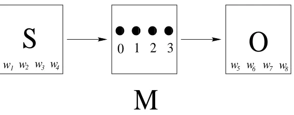
5 6 7 8 [image:8.612.165.452.56.169.2]M
Figure 4: A Widget Dispensing Machine
behaviour agent may carry on handling messages1. Any incoming message matching
p
2is a response to the messages
e
1; the response of agent is defined bye
2.The semantics of let is defined by a syntax translation to the basic design notation:
agentf(
t;v
)gfm
g= casem
of:::
p
1!(agentf(
t;v
)g+wait;e
1) whererec waitf
m
g=case
m
ofp
2 !e
2 else(wait
;
;) end:::
end
The locally created behaviour wait is used to extend agent with a handler for the response to messages
e
1. Typi-cally, when the response occurs,e
2will revert back to the original behaviour agent.4
Requirements and Initial Specification
Software to control a simple machine (see figure 4) for dispensing widgets is required. The machine consists of a store of widgets,4buttons, an output tray and a two-tone beeper. The buttons are labelled0–3. In order to dispense a widget the operator must press the buttons1,2and3in order. At any time the operator may cancel the operation by pressing0. Widgets are removed from the store and delivered to the output tray when they are dispensed. If the operation succeeds the beeper makes a high beep otherwise the beeper makes a low beep. Each widget has a unique identity.
An initial attempt at the required behaviour is shown in figure 5. The behaviour function
M
has two state com-ponentss
ando
that are sets of widgets representing the store and output respectively. Input messages0–2cause no state change and no output messages. Input message3from source objectt
0
causes a widget to be dispensed and added to the output tray
o
if available in the stores
. A boolean reply is sent to the source of the message causing a high beep (true) if successful and a low beep (false) if the operation failed. The initial behaviour is under specified since it includes the required behaviour, but also permits illegal sequences of buttons.1In fact we only require agent to handle messages which it sends to itself. The extra machinery for this feature is straightforward but would
M
f(t;
(s;o
))gfm
g= casem
of0!(
M
f(t;
(s;o
))g;
;) 1!(M
f(t;
(s;o
))g;
;) 2!(M
f(t;
(s;o
))g;
;) (t
0
;
3)! cases
of;!(
M
f(t;
(s;o
))g;
f(t;t
0;
false)g) f
w
g[s
0
!(
M
f(t;
(s
0;o
[f
w
g))g;
f(t;t
0;
true)g) end
end
Figure 5: Initial Specification
5
A Simple System Invariant
A simple system property is that the number of widgets available in both the store and the output tray is an invariant,
i.e. pushing buttons cannot cause widgets to be introduced or lost. This can be expressed as a behaviour:
I
f(t;w
)gfm
g=(I
f(t;w
)g;
;)together with a behaviour morphism from
M
toI
that translates anM
state(s;o
)to anI
state#s
+#o
and is identity everywhere else. In order to show thatI
is an invariant we show that the limit on the diagramM
is the same as the limit on the diagramM
!I
.Theorem 6
I
is an invariant ofM
.The proof shows that there exists a total behaviour morphism
:M
!I
such that a limit on the diagram containingM
is unchanged (isomorphic to) a limit on the diagram containing:M
!I
. The mapping is defined as follows: 1f(
t;
(s;o
))g=f(t;
#s
+#o
)g 2 (m
)=8 < :
[] when
m
=[][(
i;
;)] whenm
=[(i;
)] 2 (m
1 )++
2 (
m
2
) when
m
=m
1++
m
2Proposition 1 The behaviour morphism
defines a total graph homomorphism.The following proof is by induction on the length of object calculations. Consider any
M
transitionM
f(t;
(s;o
))gm
;!M
f(t;
(s
0;o
0))gand proceed by case analysis on the message sequence
m
. Note that we omit any message information that is not relevant or can be inferred from context.When
m
=[(0;
;)], 2(
m
) =m
,f(t;
(s;o
))g=f(t;
(s
0;o
0))gand therefore
1f(
t;
(s;o
))g = 1f(
t;
(s
0;o
0))g. The same argument holds for
m
=[],m
=[(1;
;)]andm
=[(2;
;)]. Whenm
=[(3;O
)],2
(
m
)=[(3;
;)]and eithers
=;ors
6=;; we proceed by case analysis ons
. Whens
=;,O
=f(t;t
0;
false)g,f(
t;
(s;o
))g=f(t;
(s
0;o
0))gand therefore
2f(
t;
(s;o
))g = 2f(
t;
(s
0;o
0))g. When
s
=fw
g[s
0,
o
0=f
w
g[o
andO
=f(t;t
0;
true)g, therefore:
2f(
t;
(s;o
))g =f(t;
#(fw
g[s
0)+#(
o
0;f
w
g))g =f(t;
1+#s
0 +#
o
0 ;1)g =
2 f(
t;
(s
0
;o
0))g+1;1 =
2 f(
t;
(s
0
;o
0 ))g Whenm
=m
1 ++
m
2then assume by induction that the invariant is true for both
M
f(
t;
(s;o
))gm
17;!
M
f(t;
(s
0;o
0))g and
M
f(t;
(s
0
;o
0 ))gm
27;!
M
f(t;
(s
00;o
00))gand is therefore true by definition for
M
f(t;
(s;o
))gm
1+ +
m
2
7;!
M
f(t;
(s
00;o
00))g. It remains to show that
M
is a limit on diagrams containingM
and:M
!I
respectively.P
f(t;
)gfm
g= casem
of0!(
P
f(t;A
)g;
;)1!case
ofA
!(P
f(t;B
)g;
;)end 2!caseofB
!(P
f(t;C
)g;
;)end 3!caseofC
!(P
f(t;A
)g;
;)end endFigure 6: Legal Message Sequences
The proof follows directly from the properties of the identity morphism. Now consider the second diagram. Firstly construct a product
M
I
in which nodes are labelled with states from the free product states(M
)states(I
). Note that the product contains states that are legalf((t
1
;
(
s;o
));
(t
2;
#
s
+#o
))gand those that are not. Now construct an equalizere
:L
!M
I
such that1
e
=2
e
:L
? e
M
I
@@ @ R 1 ; ; ;
2
M
-I
The behaviour
L
is a limit on the diagram and contains just those states that are legal. The limitL
is not exactly the same asM
but there exists an isomorphism between them. Therefore we conclude that:M
!I
is a property ofM
. QED6
Removing Illegal Message Sequences
The behaviour
M
is under specified since it permits buttons on the machine to be pressed in illegal sequences. Object-oriented design notations such as UML restrict behaviours such asM
using state transition models that impose order-ings on sequences of permitted message calls. The machine consists of three states referenced as1,2and3.The initial state for the machine is1. Button1may only be pressed in state1causing a state change to2. Button 2may only be pressed in state2causing a state change to3. Button3may only be pressed in state3causing a state change to1; a widget is dispensed as a side effect. Button0may be pressed in any state causing a change to state1.
The state transition machine is expressed as a behaviour function
P
in figure 6. The behaviour describes a single state componentwhose value is the machine state. The behaviour handles all machine messages making appropriate state changes but otherwise does nothing.Behaviour
M
includes all correct behaviour but also includes incorrect behaviour. Applying the constraintP
toM
will produce just the required behaviour. The constraint is applied by combiningM
andP
using the behaviour combination operator. This produces a new behaviourM
0
=
M
P
shown in figure 7. The behaviourM
0has a state(
s;o;
)that is the combination of states fromM
andP
. Message dispatch has been combined so that the conditions from bothM
andP
are taken into account. The multiple patterns(0;
)for all stateshas been combined into a single pattern(0;
)since the same transition occurs in all cases. Notice that the machine simply ignores buttons that are pressed out of sequence and that if an operator gets into trouble they may always press0to reset the machine.7
Object-Oriented Encapsulation
The behaviour
M
0does not observe the principle of encapsulation since the state(
s;o
)accesses state components of boths
ando
. In order to be object-oriented, the behaviourM
0M
0f(
t;
(s;o;
)gfm
g= case(m;
)of(0
;
)!(M
0f(
t;
(s;o;A
))g;
;) (1;A
)!(M
0
f(
t;
(s;o;B
))g;
;) (2;B
)!(M
0
f(
t;
(s;o;C
))g;
;) (t
0
;
(3
;C
))! cases
of;!(
M
0f(
t;
(s;o;A
))g;
f(t;t
0;
false)g) f
w
g[s
0 !(
M
0 f(
t;
(s
0
;o
[f
w
g;A
))g;
f(t;t
0;
true)g) end
end
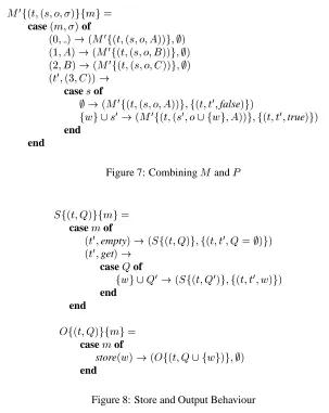
Figure 7: Combining
M
andP
S
f(t;Q
)gfm
g= casem
of(
t
0;
empty)!(
S
f(t;Q
)g;
f(t;t
0;Q
=;)g) (
t
0
;
get)! caseQ
off
w
g[Q
0!(
S
f(t;Q
0)g
;
f(t;t
0;w
)g) end
end
O
f(t;Q
)gfm
g= casem
of [image:11.612.146.449.53.434.2]store(
w
)!(O
f(t;Q
[fw
g)g;
;) endFigure 8: Store and Output Behaviour
changing state in both
s
ando
must occur via message passing.Although both
s
ando
are represented as sets of widgets, they are used in different ways. These differences may result in radically different implementation strategies and so we implement each as a separate behaviour in figure 8. A store behaviourS
handles messages empty and get. The former replies with true when the store is empty and the latter replies with an element of the store selected at random. An output tray behaviourO
handles a single messagestore containing a widget
x
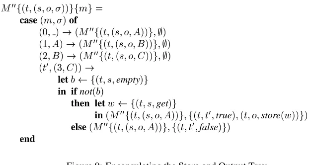
. The widget is added to the output tray.The behaviour function
M
0must be refined in order to use references to the store and output tray. The result is a new behaviour function
M
00shown in figure 9. When
M
00receives a message3from object
t
0in state3it sends a message empty to the store and waits for the reply. If the store is not empty then
M
00sends it another message get and waits for a widget to be returned. On receiving the widget
x
,M
00sends a store(
x
)message to the output tray. Finally,M
00replies to
t
0with true or false.
Theorem 7
S
M
00M
00f(
t;
(s;o;
))gfm
g= case(m;
)of(0
;
)!(M
00f(
t;
(s;o;A
))g;
;) (1;A
)!(M
00
f(
t;
(s;o;B
))g;
;) (2;B
)!(M
00
f(
t;
(s;o;C
))g;
;) (t
0
;
(3
;C
))!let
b
f(t;s;
empty)g in if not(b
)then let
w
f(t;s;
get)g in(M
00
f(
t;
(s;o;A
))g;
f(t;t
0;
true)
;
(t;o;
store(w
))g) else(M
00
f(
t;
(s;o;A
))g;
f(t;t
0;
[image:12.612.138.451.57.223.2]false)g) end
Figure 9: Encapsulating the Store and Output Tray
A proof of correctness for a refinement is established by defining a refinement homomorphism(
1;
2):
1f(
t;
(t
s
;t
o
;
));
(t
s
;s
);
(t
o
;o
)g=f(t;
(s;o;
))g 2 (m
)=8 > > > > < > > > > :
[] when
m
=[][(
i;
;)] whenm
=[(i;
;)]8i
20:::
2 3;
get;
empty;
true;
false whenm
=[(3;
ffalseg)] 3;
get;
empty;
false;
get;w;
true;
store(w
) whenm
=[(3;
ftrueg)] 2 (m
1 )++ 2 (m
2) when
m
=m
1 ++
m
2 Theorem 8 (
1
;
2 ):M
0
!
S
M
00O
is a refinement homomorphism. The proof must establish that for all transitionsM
0(
1(
W
))m
7;!M
0 (
1 (
W
0
))there exists a transition(
S
M
00
O
)W
2(
m
)7;! (
S
M
00O
)W
0. The refinement is complete if it holds for all transitions performed by
M
0and is sound if it holds for all transitions performed by
S
M
00
O
. The proof is by induction on the structure ofm
; we proceed by case analysis ofm
.When
m
=[], since 2(
m
)=[],W
=W
0and
1(
W
)= 1(
W
0). When
m
=[(f0g;
;)]then 2(
m
)=[(f0g;
;)] and for anyW
= f(t;
(t
s
;t
o
;x
);
(t
s
;s
);t
o
;o
)g,W
0
= f(
t;
(t
s
;t
o
;A
));
(t
s
;s
);
(t
o
;o
)g, thereforeM
0(
1(
W
))m
7;!M
0 ( 1 (W
0)). When
m
=[(f1g;
;)]andm
=[(f2g;
;)]the proof has the same structure as that form
=[(f0g;
;)]. Whenm
=[(f3g;
fb
g)]withb
= false then2
(
m
)= get;
empty;
true;
false,W
= f(t;
(t
s
;t
o
;C
));
(t
s
;
;);
(t
o
;o
)g, thereforeW
0=
W
andM
0(
1(
W
))m
7;!M
0 (
1 (
W
0
)). When
m
= [(f3g;
fb
g)]withb
= true then 2(
m
) = get;
empty;
false;
get;w;
true;
store(w
),W
=f(t;
(t
s
;t
o
;C
));
(t
s
;
fw
g[s
);
(t
o
;o
)gand therefore:W
0=f(
t;
(t
s
;t
o
;A
));
(t
s
;s
);
(t
o
;
fw
g[o
)gM
0 (1 (
W
))m
7;!M
0 (
1 (W
0 )) Whenm
=m
1 ++
m
2we assume by induction than the theorem holds for the sequences
m
1andm
2and therefore it holds form
by the transitivity of7;!. QED8
Concrete Data Representation
S
0f(
t;
(Q;i
))gfm
g= casem
of(
t
0;
empty)!(
S
0f(
t;
(Q;i
))g;
f(t;t
0;i
=;1)g) (
t
0
;
get)!(
S
0f(
t;
(Q;i
;1))g;
f(t;t
0;Q
[
i
])g) endO
0f(
t;
(Q;i
))gfm
g= casem
ofstore(
x
)!(O
0f(
t
(Q
[i
]:=x;i
+1))g;
;) endFigure 10: Refinement of Store and Output Tray Behaviours
The states of
S
0 andO
0consist of an indexed set
Q
and an indexi
. The values inQ
are indexed by integers from 0upwards andi
+1is the size of the indexed set. Given an indexed setQ
, the value associated with indexk
isQ
[k
]. The indexed set is extended with a valuex
indexed byk
to produceQ
[k
]:=x
.Theorem 9
S
0M
00
O
0
is a legal refinement of
S
M
00O
A proof follows from theorem 5 and the existence of two refinements from
S
toS
0and from
O
toO
0. The refinement
(
1;
2):
S
!S
0is defined as follows:
1f(
t;
(Q;i
))g=f(t;
fQ
[j
]jj
20:::i
g)g 2(
m
)=m
Notice that(1
;
2)reduces the non-determinism occurring in
S
since the get method always returns widgets in a particular order for a given state.9
Implementation in Java
Composition of refinement morphisms by theorem 4 shows the resulting system
S
0M
00
O
0
to be a valid refinement of the initial specification
M
. The system is implemented by identifying a one-to-one correspondence between the design components and programming language components that give rise to the same behaviour. Each behaviour function corresponds to a Java class. Each state component of a behaviour function corresponds to a private field. Each message handled by a class corresponds to a public method.The implementation is given in figure 11. During implementation we may identify certain behaviours that are consistent with behaviours provided by existing Java classes. This occurs here with
S
0and
O
0both of which are consistent with the behaviour ofVector.
References
[Aba98] Abadi, M. & Cardelli L.: A Theory of Objects. Springer, 1998.
[Agh86] Agha, G.: Actors: A Model of Concurrent Computation in Distributed Systems. MIT Press, 1986.
[Agh91] Agha, G.: The Structure and Semantics of Actor Languages. In proceedings of REX School/Workshop on Foundations of Object-Oriented Languages, LNCS 489, Springer-Verlag, 1991.
class M {
private Store s; private OutputTray o; private int state = 1;
public M(Store s,OutputTray o) { this.s = s; this.o = o; } public void zero() { state = 1; }
public void one() { if(state == 1) state = 2; else error(); } public void two() { if(state == 2) state = 3; else error(); } public void three()
{
if(state != 3) error(); else {
if(!s.empty()) o.store(s.get()); state = 1;
} } }
class Store { private Vector q;
public Store(Vector q) { this.q = q; }
public boolean empty() { return q.size() == 0; }
public Widget get() { return (Widget)q.removeElement(); } }
class OutputTray {
private Vector q = new Vector();
public store(Widget x) { q.addElement(x); } }
Figure 11: Implementation of Machine
[Bic97] Bicarregui, J., Lano, K. & Maibaum, T.: Towards a Compositional Interpretation of Object Diagrams. Tech-nical Report, Department of Computing, Imperial College, 1997.
[Cla97] Clark, A. N. & Evans, A. S.: Semantic Foundations of the Unified Modelling Language. In the proceedings of the First Workshop on Rigorous Object-Oriented Methods: ROOM 1, Imperial College, June, 1997.
[Cla99a] Clark, A. N.: A Semantics for Object-Oriented Systems. Presented at the Third Northern Formal Methods Workshop. September 1998. To appear in BCS FACS Electronic Workshops in Computing, 1999.
[Cla99b] Clark, A. N.: A Semantics for Object-Oriented Design Notations. Technical report, submitted to the BCS FACS Journal, 1999.
[Cla99c] Clark, A. N.: A Semantic Framework for Object-Oriented Development. Technical report, Computing De-partment, University of Bradford, 1999.
[Ehr91] Ehrich, H-D., Goguen, J. A. & Sernadas, A.: A Categorical Model of Objects as Observed Processes. In the proceedings of REX School/Workshop on Foundations of Object-Oriented Languages, LNCS 489, Springer-Verlag, 1991.
[Eva98] Evans, A. S.: Reasoning with UML Class Diagrams. In WIFT ’98, IEEE Press, 1998.
[Eva99] Evans, A. S. & Lano, K. C.: Rigorous Development in UML. To appear in the proceedings of the ETAPS ’99, FASE Workshop, 1999.
[Gog75] Goguen, J.: Objects. Int. Journal of General Systems, 1(4):237–243, 1975.
[Gog90] Goguen, J. A.: Sheaf Semantics for Concurrent Interacting Objects. Mathematical Structures in Computer Science, 1990.
[Han94] Hankin, C.: Lambda Calculi A Guide for Computer Scientists. Clarendon Press, Oxford. 1994.
[Ken99] Kent, S. & Gil J.: Visualising Action Contracts in Object-Oriented Modelling. To appear in the IEE Software Journal, 1999.
[Ken97] Kent, S.: Constraint Diagrams: Visualising Invariants in Object-Oriented Models. In the proceedings of OOPSLA 97, ACM Press, 1997.
[Lan64] Landin P.: The Next 700 Programming Languages. Communication of the ACM, 9(3), 1966, pp 157 – 166.
[Lan98] Lano, K. & Bicarregui, J.: UML Refinement and Abstraction Transformations. In the proceedings of the Second Workshop on Rigorous Object-Oriented Methods: ROOM 2, Bradford, May, 1998.
[Plo75] Plotkin, G.: Call-by-name, call-by-value and the lambda calculus. Theoretical Computer Science, 1, pp 125 – 159.
[Rui95] Ruiz-Delgado, A., Pitt, D. & Smythe, C.: A Review of Object-Oriented Approaches in Formal Specification. The Computer Journal, 38(10), 1995.
[Ryd88] Rydeheard, D. E. & Burstall, R. M.: Computational Category Theory. Prentice Hall International Series in Computer Science, 1988.
[UML98] The UML Notation version 1.1, UML resource center, http://www.rational.com.
A
The Theory
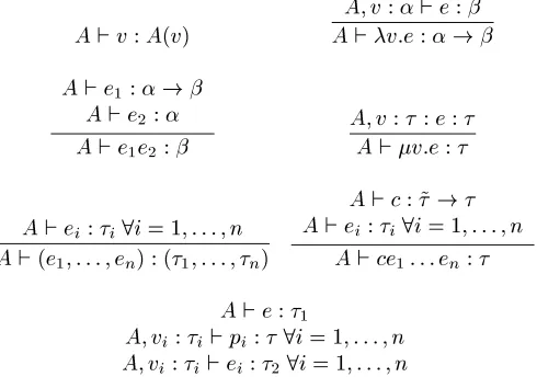
[image:15.612.184.431.411.603.2]o
Figure 12 defines a semantics for the
o-calculus using a convertibility relation between terms. Figure 13 defines a type theory for
o-terms.
(v:e 1
)e 2
=e 1
[v:=e 2
] v:e=e[v:=v:e] e
1 = (p)= casee
1of
:::p!e 2
::: end=e 2
e=e 0 v:e=v:e
0
e 1
=e 0 1 e
2 =e
0 2 e
1 e
2 =e
0 1
e 0 2
e=e 0 v:e=v:e
0
e i
=e 0 i
8i=1;:::;n (e
1 ;:::;e
n )=(e
0 1
;:::;e 0 n
) e
i =e
0 i
8i=1;:::;n ce
1 :::e
n =ce
0 1
:::e 0 n e=e
0 e
i =e
0 i
8i=1;:::;n caseeofp
1 !e
1 ;:::;p
n !e
nend = casee
0 ofp
1 !e
0 1
;:::;p n
!e 0 nend Figure 12: The Theory
A`v:A(v)
A;v:`e: A`v:e:! A`e
1
:! A`e
2 : A`e
1 e
2 :
A;v: :e: A`v:e:
A`e i
: i
8i=1;:::;n A`(e
1 ;:::;e
n ):(
1 ;:::;
n )
A`c:~! A`e
i :
i
8i=1;:::;n A`ce
1 :::e
n : A`e:
1 A;v
i :
i `p
i
:8i=1;:::;n A;v
i :
i `e
i :
2
8i=1;:::;n A`caseeofp
1 !e
i ;:::;p
n !e
nend :
[image:16.612.185.430.258.430.2]2 Figure 13: Type Theory for