THE DEVELOPMENT OF ALTERNATIVE CATHODES FOR
HIGH TEMPERATURE SOLID OXIDE ELECTROLYSIS
CELLS
Xiangling Yue
A Thesis Submitted for the Degree of PhD at the
University of St Andrews
2013
Full metadata for this item is available in Research@StAndrews:FullText
at:
http://research-repository.st-andrews.ac.uk/
Please use this identifier to cite or link to this item: http://hdl.handle.net/10023/6531
This item is protected by original copyright
The Development of Alternative Cathodes for
High Temperature Solid Oxide Electrolysis Cells
This thesis is submitted in partial fulfilment for the degree of PhD
at the
University of St Andrews
By
Xiangling Yue
Supervised by Prof. John T S Irvine
The Development of Alternative Cathodes for High
Temperature Solid Oxide Electrolysis Cells
Xiangling Yue, PhD thesis
Declarations
1. Candidate’s declarationsI, Xiangling Yue, hereby certify that this thesis, which is approximately 55,000 words in length, has been written by me, that it is the record of work carried out by me and that it has not been submitted in any previous application for a higher degree.
I was admitted as a research student in Oct, 2008 and as a candidate for the degree of PhD in Oct, 2009; the higher study for which this is a record was carried out in the University of St Andrews between 2008 and 2013.
Date ……… Signature of candidate………
2. Supervisor’s declarations
I hereby certify that the candidate has fulfilled the conditions of the Resolution and Regulations appropriate for the degree of PhD in the University of St Andrews and that the candidate is qualified to submit this thesis in application for that degree.
Date……….. Signature of supervisor………..
3. Permission for electronic publication:
In submitting this thesis to the University of St Andrews I understand that I am giving permission for it to be made available for use in accordance with the regulations of the University Library for the time being in force, subject to any copyright vested in the work not being affected thereby. I also understand that the title and the abstract will be published, and that a copy of the work may be made and supplied to any bona fide library or research worker, that my thesis will be electronically accessible for personal or research use unless exempt by award of an embargo as requested below, and that the library has the right to migrate my thesis into new electronic forms as required to ensure continued access to the thesis. I have obtained any third-party copyright permissions that may be required in order to allow such access and migration, or have requested the appropriate embargo below.
The following is an agreed request by candidate and supervisor regarding the electronic publication of this thesis:
(i) Access to printed copy and electronic publication of thesis through the University of St Andrews.
Date ……….
Acknowledgements
This thesis is dedicated to my husband, Liang Wei. Pursuing a PhD requires hard work, intense focus and long hours, without his understanding and support all these years when I was far away from home, I would not make it. Not mention his willingness to come to the UK to join me and spend a lot time looking after our baby boy, so that I could focus on writing.
I would like to express my gratefulness to my supervisor, Prof. John Irvine, for giving me the opportunity to carry out this work, and for providing me with a lot of helpful suggestions, discussion and expert advice. Without his guidance, this work would not be possible.
I wish to thank the following members in Prof. John Irvine’s group: Cristian Savaniu and Mark Cassidy for their help and discussion in cell fabrication; Paul Connor for advice and suggestions on software utilization and impedance fitting; David Miller and Gael Corre for help in solving testing-related problems; Julie Nairn for help in chemical/gas purchase and many lab-related matters. I also wish to thank Ross Blackley and Zixue Su (who has left St Andrew) for giving me trainings and help on SEM measurement, James Rennie for designing and building up the vacuum impregnation equipment for me and George Anthony for fixing up all the broken pieces I brought to his workshop.
I also wish to thank all the other members in our research group for useful discussions and advice. And I would like to thank Xuedi Yang and Xiaoxiang Xu for a lot of help in getting me familiar with the surroundings when I first arrived at St Andrews, and all my other friends who made my life in St Andrews enjoyable.
My sincere thanks go to my parents, my brothers and my sister for their spiritual support from thousands miles away. And my special thanks go to my 10-month baby boy, Jeromy Chuyan Wei, who has brought me a lot of happiness and joy ever since his birth.
Abstract
This study mainly explores the development of alternative cathode materials for the electrochemical reduction of CO2 by high temperature solid oxide electrolysis cells (HTSOECs), which operate in the reverse manner of solid oxide fuel cells (SOFCs). The conventional Ni-yttria stabilized zirconia (YSZ) cermets cathode suffered from coke formation, whereas the perovskite-type (La, Sr)(Cr, Mn)O3(LSCM) oxide material displayed excellent carbon resistance. Initial CO2 electrolysis performance tests from different cathode materials prepared by screen-printing showed that LSCM based cathode performed poorer than Ni-YSZ cermets, due to non-optimized microstructure. Efforts were made on microstructure modification of LSCM based cathodes by means of various fabrication methods. Among the LSCM/YSZ graded cathode, extra catalyst (including Pd, Ni, CeO2, and Pt) aided LSCM/GDC (Gd0.1Ce0.9O1.95) cathode, LSCM impregnated YSZ cathode, and GDC impregnated LSCM cathode, the GDC impregnated LSCM cathode, with porous LSCM as backbone for finely dispersed GDC nanoparticles, was found to possess the desired microstructure for CO2splitting reaction via SOEC. Incorporating of 0.5wt% Pd into GDC impregnated LSCM cathode gave rise to an Rp of 0.24 Ω cm2 at open circuit voltage (OCV) at 900oC in CO2-CO 70-30 mixture, comparable with the Ni/YSZ cermet cathode operated in the identical conditions.
Table of contents
Declarations………...…...I
Acknowledgements……….………II
Abstract………..………III
Table of contents………..………..…….V
Chapter 1: Literature review
1.1 Introduction………..….…..2
1.2 Solid oxide electrolysis cells (SOECs)………..………..….….. 6
1.2.1 Principle of solid oxide electrolysis cells……….………....…7
1.2.2 Thermodynamics of SOEC……….……..9
1.2.3 Characteristics of solid oxide electrolysis cells ... 12
1.3 High temperature CO2electrolysis via SOEC………...15
1.4 Materials for high temperature SOECs used for CO2electrolysis………16
1.4.1 Electrolyte... 16
1.4.2 Cathode ... 19
1.4.2.1 Ni-cermet cathodes... 20
1.4.2.2 LSCM perovskite cathodes ... 21
1.4.2.3 Doped ceria cathodes ... 24
1.4.2.4 (La1-xSrx)TiO3perovskite cathodes ... 25
1.4.3 Anode... 26
1.5 Triple phase boundaries (TPBs)………27
1.6 Aims of study………28
References………...29
Introduction……….35
2.1 General recipe for screen-printing ink preparation………35
2.2 General steps for single cell preparation………...37
2.2.1 Single cells with fuel electrode made from screen-printing……...………39
2.2.2 Single cells with a gradient cathode structure………..…………..…….41
2.2.3 Single cells with fuel electrode on an impregnated architecture ... 42
2.3 Cell testing set-up and gas flows………...45
2.3.1 Single cell testing set-up ... 45
2.3.2 Gas supply... 47
2.4 Material characterization………...48
2.4.1 Thermal gravimetric analysis (TGA)... 48
2.4.2 X-ray diffraction (XRD) pattern ... 49
2.5 Single solid oxide cell characterization……….51
2.5.1 Single cell electrochemical characterization... 51
2.5.2 Single cell microstructure characterization... 56
2.6 Single cell electrolysis efficiency analysis………59
2.6.1 Gas chromatography (GC)... 59
2.6.2 Calculation of electrolysis efficiency... 60
References………...60
Chapter 3: Carbon sensitivity study on different potential cathode
materials
Introduction……….643.1 Carbon sensitivity on Ni-YSZ cathode………..65
3.1.1 Ni/YSZ pellets preparation, treatment and post-characterization... 65
3.1.2 Microstructure of Ni/YSZ pellets treated in CO2/CO atmospheres... 67
3.1.3 TGA analysis on Ni/YSZ pellets treated in CO2/CO atmospheres... 69
3.1.4 XRD inspection on Ni/YSZ pellets treated in CO2/CO atmospheres... 76
3.2 Carbon sensitivity on LSCM-YSZ composite………..78
3.2.3 Thermo gravimetric analysis on LSCM/YSZ samples pre-treated in CO2/CO
50/50 mixture………...81
3.2.4 XRD measurement on LSCM/YSZ pellets after treatment in CO2/CO 50/50 atmosphere ... 82
3.3 Summary………83
References………...83
Chapter 4: Initial performance from different cathode materials for
high temperature CO
2electrolysis
Introduction……….864.1 Cell fabrication and characterization……….………87
4.2 Ni-YSZ cermet cathode performance towards CO2electrolysis……….…………..89
4.3 LSCM-YSZ composite………..95
4.3.1 Choice of current collector for LSCM/YSZ cathode………..……95
4.3.2 Performance from LSCM/YSZ composite cathode for CO2electrolysis……...97
4.4 LSCM-GDC composite cathode………..102
4.5 Comparisons between Ni-cermet and LSCM based cathode………..109
4.5.1 Microstructure comparisons.. ………..……….109
4.5.2 Performance comparisons for CO2electrolysis by SOEC………111
4.5.3 Cathode activation energy for CO2reduction via a SOEC………...…114
4.6 Stability test on LSCM/GDC cathode in CO2-CO mixture……….……116
4.7 Summary………..……….……...118
References……….119
Chapter 5: Modification of LSCM based cathode to enhance
performance for high temperature CO
2electrolysis
Introduction…..……….…1235.1 Cathode with a graded structure……….….124
5.1.1 Preparation of the graded LSCM/YSZ cathode cell……...……….…….124
5.2 LSCM/GDC composite cathode with additional catalyst……….………...…129
5.2.1 Fabrication and characterization of LSCM/GDC cathode with extra catalyst. ………129
5.2.2 Performance from LSCM/GDC composite impregnated with different catalyst... ……….………...………...…….130
5.2.3 Performance from LSCM/GDC composite cathode with different level of catalyst loading………...………..…….136
5.2.4 Microstructure analysis on LSCM/GDC composite impregnated with extra catalyst…………...………...……….…138
5.3 LSCM based cathode with impregnated architecture………..………140
5.3.1 Single cell fabrication and characterization……….….140
5.3.1.1Fabrication and characterization of LSCM impregnated YSZ cathode cell ... 140
5.3.1.2 Preparation and characterization of GDC impregnated LSCM cathode cell………..141
5.3.2 LSCM impregnated YSZ cathode……….………143
5.3.3 GDC impregnated LSCM cathode………149
5.3.3.1 Microstructure of the GDC impregnated LSCM cathode ... 149
5.3.3.2 Performance of the GDC impregnated LSCM cathode for CO2electrolysis ... 151
5.3.3.3 Effect of introducing H2on the performance of the GDC impregnated LSCM cathode for CO2electrolysis... 158
5.4 Pd and GDC co-impregnated LSCM cathode………..…………...……162
5.4.1 Manufacture and characterization of Pd and GDC co-impregnated LSCM cathode cell………162
5.4.2 Performance from Pd and GDC co-impregnated cathode in various CO2-CO atmospheres………163
5.4.3 Microstructure analysis of the Pd-GDC co-impregnated cathode material…..167
5.4.4 Stability of the Pd and GDC co-impregnated LSCM cathode for CO2 electrolysis……….168
5.5 Conclusions……….…………169
Chapter 6: Efficiency analysis on CO
2electrolysis by SOEC and CO
2electrolysis without protective gas
Introduction………...174
6.1 Gas chromatography analysis and Faraday efficiency calculation………..175
6.2 Faraday efficiency analysis for CO2electrolysis on different cathode materials for SOEC……….177
6.2.1 CO2electrolysis efficiency analysis on screen-printed LSCM/GDC cathode with extra Pt catalyst ... 177
6.2.2 CO2electrolysis efficiency on the GDC impregnated LSCM cathode for SOEC……….. .. 183
6.2.3 CO2electrolysis efficiency on the Pd-GDC co-impregnated LSCM cathode for SOEC………...………..188
6.3 CO2electrolysis without protective gas and corresponding efficiency evaluation.190 6.3.1 Performance and efficiency of CO2electrolysis in CO2-N2feed into SOEC cathode ... 190
6.3.2 Impact of 5%H2/Ar on the SOEC cathode performance and efficiency of CO2 electrolysis in CO2-N2feed... 197
6.4 Summary………...………...201
References……….202
Chapter 7: High temperature steam electrolysis and steam-carbon
dioxide co-electrolysis
Introduction………...2047.1 Steam delivery and single cell charcaterizaion………205
7.2 Steam electrolysis on LSCM/GDC cathode SOEC……….207
7.2.1 Steam electrolysis on screen-printed LSCM/GDC cathode SOEC ... 207
7.2.2 Steam electrolysis on the GDC impregnated LSCM cathode SOEC ... 213
7.2.3 Comparisons between high temperature steam electrolysis and CO2electrolysis ... 218
7.3.2 Co-electrolysis study on the GDC impregnated LSCM cathode SOEC... 223
7.3.3 Co-electrolysis in different ratio of H2O-H2-CO2-CO mixture ... 226
7.3.4 Co-electrolysis stability test in H2O-H2-CO2-CO mixtures... 228
7.4 Conclusions……….230
References……….231
General conclusions...………….………..…233
Chapter 1: Literature review
Chapter 1: Literature review
Table of Contents
1.1 Introduction ... 2
1.2 Solid oxide electrolysis cells (SOECs)... 6
1.2.1 Principle of solid oxide electrolysis cells ... 7
1.2.2 Thermodynamics of SOEC... 9
1.2.3 Characteristics of solid oxide electrolysis cells ... 12
1.3 High temperature CO2electrolysis via SOEC... 15
1.4 Materials for high temperature SOECs used for CO2electrolysis ... 16
1.4.1 Electrolyte... 16
1.4.2 Cathode ... 19
1.4.2.1 Ni-cermet cathodes... 20
1.4.2.2 LSCM perovskite cathodes ... 21
1.4.2.3 Doped ceria cathodes ... 24
1.4.2.4 (La1-xSrx)TiO3perovskite cathodes ... 25
1.4.3 Anode... 26
1.5 Triple phase boundaries (TPBs) ... 27
1.6 Aims of study ... 28
Chapter 1: Literature review
Chapter 1: Literature review
1.1 Introduction
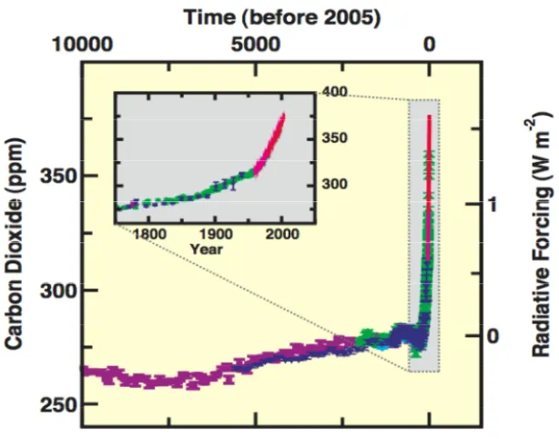
[image:21.595.147.454.400.641.2]Global atmospheric concentration of greenhouse gas has remarkably increased due to human activities since the industrial revolution in the 18thcentury. Carbon dioxide (CO2) is the primary constituent of anthropogenic greenhouse gas. Fig. 1.1 shows the atmospheric concentration of CO2over the last 10,000 years from ice cores and modern time since 1750 to 2005. The CO2 concentration in atmosphere was about 280 ppm in pre-industrial period and it had increased quickly to around 379 ppm by 2005[1]. The use of fossil fuels plays a dominant role in the increasingly vast emissions of CO2into the atmosphere, and it has been reported that the potential emissions from remaining fossil resources could lead to greenhouse gas concentration levels far above 600 ppm by 2100[2]. This undoubtedly will aggravate the global warming if the CO2emissions are not controlled.
Chapter 1: Literature review
[image:22.595.107.496.323.526.2]The majority of CO2 emissions are as a result of the heavy dependence of human activities on fossil fuels as an energy source. Shown in Fig. 1.2 is the share of energy sources in total global primary energy supply in 2008. Fossil fuels, including crude oil, coal, etc., constitute the majority sources of energy consumption in current energy system, while the renewable sources, for instance, nuclear, wind, solar, tidal, geothermal and so on, share only ca. 15% of the total energy sources, though the renewable energies have attracted increasing interest in recent years. The fossil fuels are non-renewable in nature, and their supplies are decreasing. Yet, the energy demand for human activities is still increasing. Therefore, the global issue of climate change due to the great amount of CO2 emissions and of sustainable energy production due to the depleting supply of fossil fuels is an urgent question to be addressed.
Fig. 1.2Shares of energy sources in total global primary energy supply in 2008[2]
Chapter 1: Literature review
sustainable and efficient energy supply associated with utilization/recycling of CO2 in the system.
Carbon neutral sources and/or fuels were raised and defined as those whose utilization would not lead to a net increase in the concentration of atmospheric CO2 [4]. An alternative to storing CO2 in geological reservoirs or biosphere, captured CO2 from atmosphere or from large emission sources such as power plants can be used to produce carbon neutral fuels, for instance, hydrocarbons. This has been exploited as an active R&D research topic, especially when low carbon emission sources, such as nuclear and renewable energies are incorporated as energy input.
Chapter 1: Literature review
Fig. 1.3Comparison between our current energy consumption divided by source and sector (based on data of the primary energy consumption in the U.S. for 2008) and a
hypothetical energy sources distributions with the level of CO2emissions reduced significantly by increasing the utilization portion from renewable and nuclear while
decreasing fossil fuels consumption[5]
The electrochemical conversion of CO2 to chemicals and fuels was highlighted in the comparison in Fig. 1.3, and it could play an important role in enabling the hypothetical scenario of energy make up, most significantly in reducing the fossil fuels consumption on transportation and electricity sectors. Synthetic fuels produced from cycling of CO2 could be supplied to transportation sector using electricity from renewables and nuclear energy. Meanwhile, nuclear and the intermittent renewable sources can be an alternative means for electricity generation by storing them in chemicals including H2 and carbonaceous fuels from the electrochemical conversion of CO2, with the latter being more versatile due to its wide usage in transportation fuels, electricity generation, and feedstock in industrial. These routes for reducing human dependence on fossil fuels would not increase the atmospheric concentration of CO2ascribed to that carbon neutral sources are incorporated.
Chapter 1: Literature review
renewable fossil fuels consumptions, thus, it will direct us to a more sustainable economy also a more friendly environment. What is more, carbonaceous fuels from CO2conversion are compatible with the existing petroleum infrastructure, which avoids the need to build an entirely new infrastructure as H2 fuel encounters. Actually, these fuels can be regarded as a form of H2 and carbon storage, which offer a better way to store H2. When renewable energy is utilized for CO2 electrochemical reduction, the resulting fuels can be viewed as energy carriers with higher energy density, in comparison with H2, an energy carrier but with a lower volumetric energy density[6].
There are several pathways for the electrochemical conversion of CO2, including electrolytic reduction in aqueous solution [7-9], high temperature electrolysis [10, 11], and photo electrochemical/catalytic reduction[12, 13]. Of all these, the electrochemical reduction of CO2 via high temperature solid oxide electrolysis cells (SOECs) has been identified as one of the most promising approaches[11].
The electrochemical reduction of CO2 has been extensively studied in aqueous alkaline solution utilizing various metal electrodes [7-9, 14, 15]. This low temperature process underwent several crucial problems, such as low reaction kinetics due to the low CO2 solubility in aqueous electrolyte which required high pressure to get more CO2available for reaction[8, 12], catalyst deactivation from graphite and/or hydroxide poisons[7, 14], and requirement of PH control for desirable product selectivity etc [7]. Compared with the low temperature electrolysis in aqueous solutions, the high temperature CO2 electrolysis by SOECs has several positive traits. It employs an all solid state device, thereby avoids the problems associated with utilizing of aqueous electrolyte, e.g. leakage and corrosion. It works in the temperature range of 700-1000oC, such high temperature operation not only decreases the electricity demand, but also guarantees fast electrode kinetics and thus low resistance. These positive traits of high temperature CO2 electrolysis by SOECs have motivated research into the materials development and mechanisms investigation.
1.2 Solid oxide electrolysis cells (SOECs)
Chapter 1: Literature review
H2/CO and O2. The former could act as the basis for chemical production via Fischer-Tropsch synthesis, and the latter was considered as propellant and important life support consumables for Mars missions [17-19]. The SOEC techniques were also carried out within the HotElly project for H2production, and high efficiencies (40-50%) from high temperature steam electrolysis were demonstrated [20, 21]. However, the SOEC study for CO2electrolysis was soon stopped and efforts were turned to the reverse reaction, i.e. solid oxide fuel cells (SOFC) for electricity generation due to the low price of crude oils at 1990s.
In recent years, SOEC applications in electrochemical reduction of CO2 and green H2 production have retrieved increasing interest due to its potential rewards both in energy and environmental aspects. SOECs provide an efficient and environmental friendly means of H2production compared to steam reforming, which is presently the approach of massive H2production [22]. As for CO2 dissociation, SOEC offers a way to recycle CO2 into chemicals and fuels, which helps to reduce the accumulation of atmospheric CO2and relieve the pressure from shrinking supply of fossil fuels[11]. Combined with CO2 capture and CO2 gas separation technologies, SOEC can present a promising way to realize the carbon neutral cycling of fuels.
Furthermore, vigorous development of SOFC has taken place during the last two decades [23]. The developed materials and techniques in SOFC facilitate SOEC expansion as they work in reverse manner. The same device can work as an energy convertor to generate electricity in SOFC direction and to produce chemicals to store excess electricity in SOEC direction and use these chemicals when necessary. Most attractively, when the excess electricity is from the intermittent renewable energy sources (wind, tidal etc.), the process in SOEC direction thus offers a means to store the renewable energy in the form of H2/CO, with the added possibility of using this H2/CO as a transportation fuel or a feedstock for the production of transportation fuels.
1.2.1 Principle of solid oxide electrolysis cells
Chapter 1: Literature review
can work both as SOFC and SOEC is shown in Fig. 1.4, with the working principles for both operations sketched in the graph. In SOFC, O2 is dissociated to oxide ions which diffuse to the other side of electrolyte, where H2/CO is oxidized by these oxide ions. Electricity is produced during this whole process. While in SOEC, the reverse reaction happens. That is electricity is supplied to drive the H2O/CO2 splitting to oxide ions, which transport through electrolyte and combine with each other to form O2 on the other side.
Fig. 1.4Schematic graph of a SOFC and a SOEC and their working principles
Both SOFC and SOEC consist of a dense, gas tight, and ion-conducting electrolyte (the grey layer in Fig. 1.4) sandwiched between two porous electrodes. The conventional material for electrolyte is zirconia (ZrO2) ceramic, with trivalent cations (e.g. Y3+, Sc3+) as dopant to stabilize a cubic structure and introduce oxygen vacancy defects [24]. The green layer is the negative electrode or fuel electrode (cathode in SOEC and anode in SOFC mode), and the blue layer is the positive electrode or air electrode (anode in SOEC while cathode in SOFC mode).
Chapter 1: Literature review
of steam to H2and oxygen anions, as shown in Equation 1.1, occurs on the cathode side of an SOEC.
HଶO + 2eି = Hଶ + Oଶି (Equation 1.1)
The produced oxygen anions then diffuse to the anode side through electrolyte by vacancy mechanism. While the combination of oxygen anions to O2, as shown in Equation 1.2, takes place on the anode side of an SOEC.
ܱଶି = 2݁ି +ଵ
ଶܱଶ (Equation 1.2)
Similar to water electrolysis, the CO2 electrolysis involves the reduction of CO2 to carbon monoxide and oxygen ions on the cathode side, as shown in Equation 1.3,
ܥܱଶ+ 2݁ି = ܥܱ+ ܱଶି (Equation 1.3)
the transport of oxygen ions through the electrolyte membrane and the recombination of oxygen ions at the anode (Equation 1.2). The whole process of H2O/CO2 electrolysis embraces not only the above steps, but also others including the diffusion of reactant gas from bulk gas to the surface of cathode, the surface diffusion of reactant gas or intermediate species to the active reaction sites, and the products from the interface of electrode/electrolyte to the surface of electrode etc. In summary, the heterogeneous electrochemical reduction of H2O/CO2 by SOEC is a complicated process and its fundamental mechanisms need to be investigated in details.
1.2.2 Thermodynamics of SOEC
In SOEC operation, for example, for CO2 electrolysis which involves the reaction ܥܱଶ(݃) =ܥܱ(݃) +ଵ
ଶܱଶ(݃) , a cell voltage is established between the
electrodes with different oxygen partial pressure, according the Nernst equation, listed below as Equation 1.4.
ܧ= −ீଶி−ோ்ଶிln൭(ುೀು)(ುೀమು) భ మ ುೀమ
ು
൱=ܧ−ோ் ସிln (
ቀುೀುቁమ(ುೀమು)
(ುೀమು )మ ) (Equation 1.4)
Chapter 1: Literature review
PCO2 stand for the partial pressure of CO, O2 products and CO2 reactant, respectively.
Δܩandܧis the standard free energy and cell potential for CO2 electrolysis reaction
respectively. The Nernst equation explains the relationship between the ideal standard potentialܧand cell potential at other temperatures and partial pressures of products and reactants.
When the cell is operated at open circuit, in other words, no current is flowing through circuit, the cell reaction is in an equilibrium state and the reversible thermodynamic potential, known as Nernst potential or open circuit voltage (OCV), is obtained. When considering the cell reaction as an oxygen transfer process, the Nernst potential can be simplified as:
ܧ௩= −ோ்ிlnቀభమቁ (Equation 1.5)
where P1 and P2 stand for the oxygen partial pressure at cathode and anode side of a SOEC. For an electrochemical cell, OCV indicates the minimum electric energy required for initiating and maintaining a chemical process in equilibrium state at a
constant temperature and pressure. Forܥܱଶ(݃) =ܥܱ(݃) +ଵ
ଶܱଶ(݃)process, there is:
ܭ =(ೀ)(ೀమ) భ మ
(ೀమ) (Equation 1.6)
Chapter 1: Literature review
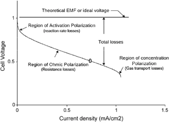
Fig. 1.5Schematic plot of I-V curve of a solid oxide cell showing different types of polarisations[32]
When there are current flows in a SOEC, the system becomes irreversible due to polarizations. Polarization is the degree that the actual cell voltage deviated from its thermodynamic open circuit voltage, which can be learned from a schematic plot of the polarization curve, namely, I-V curve, of a solid oxide cell, as displayed in Fig. 1.5. The I-V curve of a specific cell depends significantly on the composition and atmosphere of the cell as well as operational conditions.
On the I-V curve of a fuel cell, a linear region exists. This region suggests the ohmic polarization, which takes into account the IR drops from various components in the cell. In SOFC and SOEC, the ohmic loss in electrolyte is predominant, due to its ionic nature of electrolyte conductivity; therefore, the ohmic loss in electrolyte layer is dependent on the thickness of electrolyte, the electronic conductivity of electrolyte, and cell operation temperature. Because of this, it is important to make the dense, gas-tight electrolyte film as thin as possible to improve cell performance.
Chapter 1: Literature review
activation energy barrier so that the electrode reaction can be maintained at an appreciable rate, and is related to the charge transfer processes taking place on the electrode during the electrochemical reactions[17].
The concentration polarization, occurs in the high current region on the I-V curve, is related with the limiting diffusion of gaseous species through the porous electrodes. It is defined as the external energy required maintaining constant supplies of certain amount of gases that are needed for the electrode reaction. This polarization loss can be reduced by optimizing the microstructure-related porosity, pore sizes, and thickness of electrode and supplying with sufficient fuels for the reduction reaction.
Due to the irreversible polarization losses, the actual cell voltage can also be written as:
ܧ=ܧ−ܫܴ−ߟ−ߟ (Equation 1.7)
Where I is the current flowing through cell, andηୡ, ηୟare the total of activation and concentration polarization losses from cathode and anode respectively.
1.2.3 Characteristics of solid oxide electrolysis cells
Chapter 1: Literature review
Fig. 1.6The energy demand with varying temperature for high temperature steam (A) and CO2(B) electrolysis via SOEC[33]
The energy demand as a function of operation temperature for high temperature steam and CO2electrolysis is illustrated in Fig. 1.6. The total energy demand (∆H) for the high temperature SOEC is consisted of electric energy demand (∆G) and thermal energy demand (T∆S), as expressed in Equation 1.8.
∆H = ∆G + T∆S (Equation 1.8)
With increasing temperature, the required electric energy for an SOEC decreases and the thermal energy demand increases, while the total energy demand is insensitive to the operation temperature. These trends are more pronounced for an SOEC used as CO2 electrolyser.
Chapter 1: Literature review
geothermal, solar and nuclear origins and waste heat from power plants, SOEC offers an opportunity to use the intermittent renewable source as energy input and to store the renewable energies in the form of chemicals which can be easily handled.
The electrochemical reactions taking place in SOEC are endothermic in nature, which requires additional heat to initiate and maintain these reactions. Meanwhile, as long as current flows through SOEC, joule heat ascribed to the internal resistance appears. Consequently, there is a balance between the heat required by the endothermic reaction and the joule heat released from the cell. Depending on the applied electric power to SOEC, there are possibly three operation modes: endothermal mode, exothermal mode, and thermoneutral mode.
At thermoneutral mode, the joule heat generated by internal cell resistance equals to the heat consumed by the endothermic reaction happened on SOEC cathode, and the electrical-to-chemical energy conversion efficiency is 100%. The cell voltage under this mode is consequently called the thermoneutral voltage. At thermoneutral voltage, there is no need to supply/remove extra heat to/from SOEC. Given this, the thermoneutral voltage can be obtained combining Equation 1.8 and Equation 1.9, as shown below in Equation 1.10.
∆G = −nEF (Equation 1.9)
E = −∆୬ୌ (Equation 1.10)
WhereEstands for the thermoneutral voltage, while n, F, and E have their usual meanings.
Chapter 1: Literature review
Other characteristics of SOEC include its good chemical flexibility, as the same basic cell is probably capable of doing the electrolysis of steam as well as CO2. The same device can also be performed in steam-carbon dioxide co-electrolysis which produces CO and H2, known as syngas, at one goal, and is also of great interest for carbon-neutral synthetic fuel production[6, 33, and 34]. With same amount of fuels being fed in both directions, SOEC displays lower performance than SOFC, due to the difficulty in mass transport of H2O/CO2which has higher molecular weight than H2/CO[16, 33, and 35].
1.3 High temperature CO2electrolysis via SOEC
The high temperature CO2 electrolysis concept was initiated by NASA on O2 regeneration for Mars missions, most of these work was started from the early 1960s and continued to the 1980s [17-19]. This concerned O2 extraction from CO2 as propellant and life support needed for the return-trip in human exploitation of Mars missions based on the fact that the atmosphere on Mars contains over 95% CO2.
In recent years, however, interest in this technology has shifted to the product on the cathode side of SOEC due to the issue of global warming caused by high level of CO2 emissions and of searching for sustainable energy sources. The CO, produced at an SOEC cathode, can be a feedstock for a variety of synthetic fuels production, including formic acid, methanol, hydrocarbons, etc. These fuels can be converted to liquid fuels as alternatives to the electrochemically produced H2, not only because the relative ease in storage and transport of the former, but also because its compatibility with the existing fossil fuel infrastructure of the former, which will lead to a significant savings in building an entirely new H2 infrastructure. Further, the volumetric energy densities of synthetic fuels are higher than that of H2; as a result, fuel storage volume will be lower [6].
Chapter 1: Literature review
structural design, and optimization of operating conditions have to be made. Besides, understanding the mechanisms of CO2reduction reaction in SOECs is an objective that needs to be done.
1.4 Materials for high temperature SOECs used for CO2electrolysis
As SOEC and SOFC work in reversible directions and have a lot in common, the general requirements for materials selection for SOEC components are similar to those for SOFC. The current practice is to use the state-of-the-art SOFC component materials as the starting point of SOEC materials development. Identical with SOFC, SOEC is primarily composed of pore-free, ion-conducting electrolyte, porous and electrochemically active anode and cathode. The following parts will describe the general requirements of materials selection for these SOEC components, and the conventional employed materials in SOFC and steam electrolysis via SOEC applications. These materials can be the candidates in high temperature CO2electrolysis via SOEC.
1.4.1 Electrolyte
The ionic charge carrier electrolyte is one of the central components and largely determines the operation temperature of solid oxide cells. The electrolyte must be gas-tight and dense in order to separate the fuel and air compartments, must exhibit adequately high ionic conductivity allowing easy migration of oxygen anions, and must be chemical and mechanically compatible with neighbouring electrodes materials, sealants and interconnect material. It is undesirable to have electronic conduction in the electrolyte as that will cause short-circuit inside the cell and thus waste power. Moreover, it is critical for a satisfactory electrolyte maintaining its properties over a wide range of oxygen partial pressure (PO2), as the PO2may vary from ~1 atm at SOFC cathode side to ~10-20atm or even lower at SOFC anode side[23].
To date, the frequently used electrolyte materials in solid oxide cells include stabilized zirconia, doped ceria and strontium/magnesium doped lanthanum gallate[24, 36].
Chapter 1: Literature review
8 vol% yttria stabilized zirconia (YSZ) is the most common electrolyte material owing to its high purely ionic conductivity, excellent stability in oxidizing and reducing atmospheres, high quality raw material availability and fairly good mechanical strength under high temperature SOFCs working conditions.
The introduction of Y2O3 helps to stabilize the high temperature cubic fluorite structure of ZrO2 and to generate extra oxygen vacancies by charge compensation (see Equation 1.11).
ܻଶܱଷ ೝைమ
ሱ⎯ሮ 2ܻᇱೝ+ ܸை∙∙+ 3ܱை× (Equation 1.11)
The ionic conductivity of YSZ rises up to about 8 mol% yttria doping, when the cubic phase becomes stable, and then reduces with higher levels of yttria substitution due to defects association[36, 37].
The most important disadvantage of YSZ against commercial utilization is its low ionic conductivity at lower temperature, which induces significant ohmic loss in the solid oxide cells. A promising though less widely used dopant for zirconia is Scandia. Scandium stabilized zirconia (ScSZ) exhibits higher conductivity than YSZ, with the ionic conductivity of the former roughly three fold of the latter at 1000oC[38]. The high conductivity of ScSZ enables the intermediate temperature operation. Scandium and ceria co-doped zirconia was reported to be promising for steam electrolysis via SOEC at 700oC [39]. Nevertheless, the availability and high price of scandium obstructs extensive interest in this type of solid solution.
Doped ceria ceramic
Ceria based solid electrolytes also have the fluorite structure, and as zirconia, doping is a useful strategy to reinforce the oxide ion transport property. The considered dopants include yttrium, lanthanum, gadolinium and samarium, of which, gadolinium (Gd) and samarium (Sm) doped ceria with a formula of MxCe1-xO2-δ (M = Gd or Sm), denoted as
Chapter 1: Literature review
Compared with YSZ, GDC and SDC offer significantly higher ionic conductivity, particularly at lower temperature (600-800oC). Besides, GDC is chemically compatible with the state of the art electrode materials.
The major problem with doped ceria originates from the easy reducibility of Ce4+ to Ce3+in reducing environment, typical for SOFC anode conditions. This means that the doped ceria becomes a mixed ionic and electronic conductor at low Po2, which is detrimental for electrolyte because the induced electronic conduction will result in lower open circuit voltage and decreased fuel conversion efficiency.
Meanwhile, the reduction of Ce4+poses a threat to the mechanical integrity of cells, as there is volume expansion in doped ceria accompanying Ce4+ reduction in low PO2, which obviously is harmful for long-term operation.
As a result, it is of interest to utilize doped ceria as electrode components rather electrolyte. Undoubtedly, the high oxygen ion mobility and electronic paths in doped ceria is favourable for charge transfer processes in electrode reactions.
Strontium/magnesium-doped lanthanum gallate
Perovskite-type LaGaO3 can be doped with strontium and magnesium, giving La 1-xSrxGa1-yMgyO3(LSGM herein), which is an alternative electrolyte material with higher oxygen-ion conductivity than that of YSZ, especially at lowered temperatures. Therefore, LSGM materials have attracted extensive interest in applications of intermediate temperature solid oxide cells[36, 38, 43, 44].
The conductivity of LSGM is largely dependent on the dopant levels. The highest conductivity was achieved with La0.85Sr0.15Ga0.8Mg0.2O3-δ or La0.8Sr0.2Ga0.85Mg0.15O3-δ,
which was 0.15 S/cm at 800oC[45]. This value is close to the ionic conductivity of YSZ at 1000oC.
Chapter 1: Literature review
To summarize, doped ceria and doped lanthanum gallate are regarding as the two widely used alternatives of YSZ electrolyte in SOFCs, particularly those working in intermediate temperature range. As mentioned previously, the SOEC development is current at an early stage, with focus on high temperature operation, for which YSZ turns to be the best option for electrolyte material. The thin film fabrication techniques provide a means to reduce the dominant ohmic loss from YSZ electrolyte [46, 47]. By adopting an anode supported design, the performance of SOFCs with YSZ as electrolyte was markedly enhanced.
Nonetheless, the trend of lowering operation temperature will be necessary in the future, in the purpose to broaden materials selection and to debate costs, just as what happened in SOFCs. Pioneered research in this aspect was carried out by Ishihara et.al using LSGM electrolyte for steam electrolysis through intermediate temperature SOECs [48, 49].
1.4.2 Cathode
The rationale for SOEC cathode material and structure is that they should have sufficient electronic and ionic conductivities for fast charge transfer in cathode reaction, that they should be porous enough to facilitate gas diffusions to/from electrochemical active sites through bulk cathode but not too porous to maintain the continuous paths for electron and ion conductions, and that most importantly, they should exhibit high electrochemical and catalytic properties towards desirable SOEC cathode reactions. Other requirements that are crucial for selection of SOEC cathode materials include chemical and mechanical (thermal expansion behaviour) compatibility with adjacent SOEC electrolyte and interconnect components, decent thermal cycling capability, and desirable stability over long-term operation. Last but not least, they should be easily fabricated with cost-effective approaches. Currently, materials developed in SOFC anode cover Ni-cermet, perovskite structured (La, Sr)(Cr0.5Mn0.5)O3±δ (denoted as
LSCM herein) material, doped ceria, and (La1-xSrx)TiO3±δ (abbreviated as LST
Chapter 1: Literature review
1.4.2.1 Ni-cermet cathodes
The state-of-the-art anode materials in SOFC applications are Ni-based cermets, in which Ni provides electronic conductivity and catalytic activity and YSZ acts as the ionic conductor and a support for Ni distribution to prevent Ni sintering. This set of materials possesses high conductivity, good compatibility with electrolyte and excellent catalytic properties towards oxidation of fuels. Based on these positive characteristics, Ni-cermets have also been applied in high temperature steam electrolysis and CO2 electrolysis by SOECs[10, 25-31]. However, Ni-cermets suffer from several limitations.
According to knowledge has obtained in SOFC, the choice of fuels is restricted to H2 -containing fuels and to high steam to carbon (S/C) ratio reformates on Ni-cermets to avoid coke deposition in hydrocarbon-fuelled SOFC. This originates from the fact that Ni is also a superior catalyst for hydrocarbon cracking and CO disproportionation reaction (also known as the Boudouard reaction). The occurrence of coke will block pores and electrochemically active sits, and hence leads to Ni catalyst deactivation and eventually performance degradation. It has been reported that a Ni-YSZ anode that was able to obtain a power density of 1.8W/cm-2 in H2/H2O atmosphere displayed less than 0.3W/cm-2in 44%CO-56%CO2mixture at 800oC[50].
Ni-cermets exhibit slow activity towards direct CO and hydrocarbon oxidation, and limiting current density showed up for the cell working with CO/hydrocarbon fuels, as results of the higher molecular weight of CO/hydrocarbon than H2 which led to difficulty in mass transportation and most significantly of the poor carbon tolerance [50-52]. This poor tolerance necessitates the introduction of excess steam to realize a reforming route as first step. In this case, the oxidation takes place primarily through water gas shift reaction (Equation 1.12), steam reforming reaction (Equation 1.13) and H2oxidation reaction.
CO + HଶO ↔ Hଶ+ COଶ (Equation 1.12)
Chapter 1: Literature review
The presence of steam is also helpful to remove deposited coke [53], however, the introduction of surplus steam for reformates on Ni-cermets increases the complexity and costs of SOFC design in addition to a fuel diluting effect.
The poor redox stability of Ni-cermets limited its practical application in SOFCs, especially the ones for long-term operation. Formation of NiO would happen during start-up and shut-down cycles, causing volume instability and interfacial deteriorations between anode and electrolyte phases. Further, Ni tends to agglomerate during prolonged operation, which results in decreases in TPB areas and thus performance degradation.
Concerning the limitations of Ni-cermets in SOFC, the stability of Ni-cermets is of great concern as SOEC cathode working in H2O-H2and CO2-CO mixture, especially the latter. The electrolyser operation firstly necessitates the addition of sufficient protective H2 or CO gas to ensure reducing surroundings over all parts of Ni-cermets electrode, diluting fuels and decreasing efficiencies. Highly volatile Ni carbonyls are readily to form in CO rich mixture at low temperature [53, 54], leading to catalyst losses. In the meantime, Boudouard reaction (expressed in Equation 1.14), which yield solid carbon, is favourable at high CO/CO2 ratios at low temperatures. These make it crucial to engineer the fuel compositions to avoid these detrimental effects on the performance of Ni-cermets as a SOEC cathode.
2CO ↔ C + COଶ (Equation 1.14)
1.4.2.2 LSCM perovskite cathodes
Chapter 1: Literature review
Fig. 1.7Unit cell of the ABO3perovskite structure
(La0.75Sr0.25)1-xCr0.5Mn0.5O3-δ (0 ≤ x ≤ 0.1) perovskite-type material was found by Tao
and Irvine as alternative anode in SOFC[55]. The doping of Mn at a level higher than percolation limit (e.g., >33%) into the B-site of (La,Sr)CrO3 perovskite yielded a dramatically improved material with the two B-site elements acting in a complementary fashion.
LSCM forms a single-phase complex perovskite structure at high temperature firing (1100-1400oC), and is chemically compatible with YSZ to at least 1300oC. LSCM is a mixed ionic and electronic conductor (MIEC), and the total conductivity of the one in the formula of La0.75Sr0.25Cr0.5Mn0.5O3-δ at 900oC is 38.6 S/cm in air and 1.49 S/cm in
5%H2(PO2≈10-21atm)[56]. Most importantly, LSCM possesses good redox stability and resistance to sulphur poisoning and carbon depositions [57, 58], which makes LSCM versatile in high temperature SOFC running with a wide variety of fuels, including hydrocarbons. The redox stability and flexibility in choice of fuels from LSCM overcomes the major two limitations of the Ni-cermets as SOFC anode.
Chapter 1: Literature review
the methane oxidation mechanism were conducted in a fixed-bed reactor, with an approximation to the anodic conditions in SOFC [61]. A dominantly direct full oxidation route was detected with insignificant selectivity of CO and H2 on LSCM catalyst at high temperature.
Fig. 1.8The total conductivity of LSCM as a function of temperature (a) and oxygen partial pressure (PO2) in different atmospheres[56]
Generally speaking, an electronic conductivity of at least 1 S/cm is required to minimize the electrode ohmic loss. In LSCM, the substitution of Sr into the A-site results in the transition of Cr3+/Mn3+to Cr4+/Mn4+as charge compensation. This transition can lead to increase in small polaron concentration and as a result, high electronic conductivity. Being a p-type conductor, the concentration of the charge carriers in LSCM reduces at low PO2based on the formation of oxygen vacancies, expressed in Equation 1.15.
2M∙ + O× = 2M× + V∙∙ +ଵଶOଶ(g) (Equation 1.15)
Where M= Cr, Mn for LSCM. Therefore, as illustrated in Fig. 1.8, the conductivity of LSCM decreases remarkably in reducing atmosphere whereas it stays constant in oxidizing environment. This suggests that LSCM electrode may undergo inadequate electronic conductivity for current collection in reducing atmosphere, at the absence of an additional component with high electronic conductivity.
Chapter 1: Literature review
GDC nanoparticles onto LSCM by aqueous impregnation effectively improved the electrochemical activity of LSCM for methane oxidation, resulting from promoted current collection and oxide ion transport [62]. The enhancement in electrochemical properties of LSCM towards methane oxidation can also be achieved by adding dopant levels of metal catalyst, such as Pt, Ni, and Pd, which are believed to present good catalytic properties for oxidation reaction[63].
An investigation of Ni-free LSCM/YSZ composite was performed as SOEC cathode for high temperature steam electrolysis by Yang and Irvine. A sigmoidal shaped polarization curve was observed for steam electrolysis and it was found that LSCM material performed better over traditional Ni/YSZ cermets, especially in the fuels without protective H2 gas[64]. Similar, it is anticipated that LSCM based material can also be considered an alternative SOEC cathode for high temperature CO2 electrolysis. The ability of LSCM based cathode for CO2splitting through SOEC has been proven [65]. However, the report concerning employment of this material in CO2electrolysis is still scarce.
1.4.2.3 Doped ceria cathodes
As mentioned in section 1.4.1, GDC and SDC exhibit mixed conductivities in low PO2, which is harmful as electrolyte but favourable as electrode materials, thus are considered as potential alternatives to Ni-cermets in the fields of SOFC and SOEC. The high ionic conductivity of GDC/SDC is especially profitable to the oxidation reaction in SOFC anode [66, 67]. What is more, doped ceria have reasonably good catalytic activity towards various hydrocarbon oxidations without the need of adding a reformer or excess steam to avoid the formation of graphite which is highly possible on Ni catalyst. This allows SOFC to work directly with CO and more readily available hydrocarbon fuels.
Barnett et al introduced 0.5μm thin (Y2O3)0.15(CeO2)0.85 (YDC) porous films between
Chapter 1: Literature review
electrochemical oxidation of various hydrocarbons using SOFC, to suppress carbon formation. It was demonstrated that the final products of oxidation contained only CO2 and water and that reasonable power densities could be obtained [69, 70]. In Cu-ceria composite, Cu acted as current collector while ceria played an important role in catalyzing the oxidation reactions. Adding dopant level of metal catalyst, such as, Pd, is advantageous to enhance the electro-catalytic properties of the ceria based electrode [66].
In a high temperature steam electrolysis study, the addition of GDC into (La, Sr)MnO3 (LSM) anode by wet impregnation tremendously promoted the electro-catalytic activities for the oxygen oxidation reaction[71]. It also prevented delamination of LSM anode from YSZ electrolyte. Moreover, CO2 electrolysis was conducted on pure Gd0.4Ce0.6O2 cathode SOEC by Green et al, and it was reported that the vacancy diffusion coefficient and surface exchange rate of GDC electrode increased with decreasing PO2, which were beneficial for the CO2 electrochemical reduction processes occurring on SOEC cathode [72]. This indicated the potential utilization of GDC as SOEC cathode material for high temperature CO2electrolysis.
Current concerns with practical utilization of doped ceria in solid oxide cells are associated with the reactivity of doped ceria with the state of the art YSZ electrolyte and the lattice expansion/contraction of ceria resulting from transitions between Ce4+ and Ce3+in reducing/oxidizing environment. The former will introduce a detrimental inter-diffusion layer with high resistivity for ion transfer between YSZ electrolyte and doped ceria electrode[73, 74]; whereas the latter poses problems for sustainable cells in that it is possible to lead to cracks at the electrode-electrolyte interface and subsequent delamination of the electrode layer from electrolyte. Caution in fabrication method and material compositions options should be taken to avoid the above mentioned concerns [66, 70, and 75].
1.4.2.4 (La1-xSrx)TiO3perovskite cathodes
Chapter 1: Literature review
property by doping and its resistance to sulphur, which is one of the limitations of Ni-cermets anode using hydrocarbon fuels .
LST exhibits n-type semiconducting behaviour in reducing environment, giving good electronic conductivity due to the occurrence of the Ti4+/Ti3+ redox couple, which is suitable for the reducing atmosphere encountered in cathode of SOECs. Tsekouras and Irvine have employed LST /YSZ composite as SOEC cathode for steam electrolysis and demonstrated the significant role of defect chemistry in LST based electrode on its properties for high temperature steam splitting processes [78]. The steam electrolysis performance was observed to be largely independent of the presence or absence of H2in cathode inlet, indicating the superior redox stability of LST materials over the Ni-based cermets cathode.
Following on their work of utilising LST based cathode for high temperature steam electrolysis, Tsekouras et al. investigated B-site doped La0.4Sr0.4ܯ௫ାTi1-xO3-γ-δ (where
M= Fe3+ or Ni2+, x= 0.06, γ= (4-n)x/2 = inherent oxygen deficiency, and δ= oxygen
deficiency introduced upon reduction) perovskite cathode materials, in an effort to introduce metallic nanoparticles by B-site exsolution driven by A-site deficiency under reducing SOEC cathode operating conditions [79]. The exsolved electro-catalytically active Fe or Ni nanoparticles on the surface of LST cathode helped to dramatically lower the activation barrier to steam electrolysis compared to LST without B-site doping.
1.4.3 Anode
The ideal SOEC anode material should readily recombine the oxide anions to form molecular oxygen, have sufficiently high electronic and ionic conductivities, and have good chemical and thermal expansion compatibility with the neighbouring electrolyte, namely, YSZ. Optimized microstructure for ease of gaseous diffusion as well as for electrons and oxygen ions conduction is also critical for highly performed SOEC anode.
Chapter 1: Literature review
very limited, the combination of YSZ to form LSM/YSZ composite is advantageous for enhancing oxygen ions diffusion and consequently anode performance, as well as for improving anode/electrolyte interfacial attachment. As so, LSM/YSZ has been extensively applied as SOEC anode, and there are a number of reports on utilising LSM/YSZ anode in SOEC used for steam electrolysis[26-29, 31, 34].
Though efforts have been set out to find alternative SOEC anodes that will perform better due to the fact that air electrode gave higher losses in electrolysis mode than in fuel cell[34], LSM is still considered the best choice for high temperature electrolysis operation currently, regarding to its ease in fabrication, excellent long-term stability and relatively good compatibility with the commonly used YSZ electrolyte[30, 35, 80].
It is generally acknowledged that polarization activation of LSM based cathode occurs with applying current passage in SOFC, leading to increased oxygen vacancies in LSM lattice and significant enhance in cathode performance[81-83]. Similarly, a low anodic polarization current treatment was reported to improve the electrochemical properties of a freshly prepared LSM/YSZ electrode or a cathodically polarized one, though deactivation happened quickly when switching back to OCV or to fuel cell mode [31, 71, and 80]. However, high anodic polarization current resulted in separation of the LSM anode from YSZ electrolyte. These phenomena were proposed to be related to microstructural changes in LSM resulting from polarization treatment and oxygen generation/consumption with LSM reduction/oxidation [31, 71]. The mechanisms for activation/deactivation of LSM upon a low level of current polarization and for delamination upon high level of current polarization need to be fully understood.
1.5 Triple phase boundaries (TPBs)
Chapter 1: Literature review
Fig. 1.9Oxygen reduction at a pure electronic, composite and mixed ionic electronic conducting cathode in SOFCs[84]
A schematic of oxygen conduction at a pure electronic cathode, a composite cathode, and a mixed ionic and electronic conductor (MIEC) cathode in SOFCs is illustrated in Fig. 1.9. With a pure electronic conduction cathode, the TPBs area is restricted to the planar cathode/electrolyte interface; with a composite cathode that incorporates an ionic conducting phase, the TPBs area is extended to depth of cathode; and with a MIEC cathode, the TPBs area is further extended to volume cathode, so that several possible diffusion pathways exist [85]. The enlargement in TPBs area is undoubtedly beneficial to accelerate the electrode reaction processes and to reinforce electrode performance.
As a result, the TPB area offers important implications for optimization in microstructure and material properties for both cathode and anode in solid oxide cells. In general, oxide electrodes that exhibit mixed conductivities are of particular interest in solid oxide cells.
1.6 Aims of study
Chapter 1: Literature review
In this study, we will set out to find a high performance, efficient cathode material for high temperature SOECs as an alternative to Ni-YSZ cermets, with focus on CO2 electrolysis performance and behaviour since it has been scarcely reported. Cathode microstructure modification will be conducted in order to improve cathode performance for the electrochemical reduction of CO2, by adopting different cathode fabrication procedures. The mechanisms concerning the CO2 electrochemical dissociation will be investigated with the aid of impedance spectroscopy, and factors including fuel gas composition, operation temperature, and presence of extra metal catalyst will be taken into account for their impacts on the CO2 splitting process via SOECs. Faradaic efficiency of CO2 electrolysis as well as CO formation rate on different cathode SOECs will be assessed.
High temperature steam electrolysis will be studied with different level of steam supply using the identical cathode SOEC device for CO2 electrolysis, to figure out the reasons underneath the S-shaped polarization curve observed by previous researchers [64]. Finally, the highly performed cathode from CO2 electrolysis will be applied to steam-carbon dioxide co-electrolysis. Performances from the same SOEC device working for steam electrolysis, CO2 electrolysis and co-electrolysis will be characterized and compared.
References
1. S. Solomon, D. Qin, M. Manning, Z. Chen, M. Marquis, K. B. Averyt, M. Tignor and H. L. Miller, Contribution of Work Group I to the Fourth Assessment of the Intergovernmental Panel on Climate Change (IPCC), 2007: The Physical Science Basis: Summary for Policymakers.
http://www.ipcc.ch/publications_and_data/ar4/wg1/en/spmsspm-human and.html 2. O. Edenhofer, R. P. Madruga, Y. Sokona, K. Seyboth, P. Matschoss, S. Kadner, T.
Zwickel, P. Eickemeier, G. Hansen, S. Schlӧmer, C. Stechow, Renewable Energy
Chapter 1: Literature review
3. B. Metz, O. Davidson, H.Coninck, M. Loos, L. Meyer, IPCC Special Report on Carbon Dioxide Capture and Storage, Cambridge University Press, New York (2005)
4. F. S. Zeman and D. W. Keith,Phil. Trans. R. Soc. A,366, 3901 (2008) 5. D. T. Whipple and P. J. A. Kenis,J. Phys. Chem. Lett.,1, 3451 (2010)
6. Z. Zhan, W. Kobsiriphat, J. R. Wilson, M. Pillai, I. Kim, and S. A. Barnett,Energy Fuels,23, 3089 (2009)
7. H. Yano, F. Shirai, M. Nakayama, K. Ogura,J. Electroanal. Chem.,533, 113 (2002) 8. K. Hara, A. Kudo, T. Sakata,J. Electroanal. Chem.,391, 141-147 (1995)
9. T. Yamamoto, D. A. Tryk, A. Fujishima, H. Ohata, Electrochem. Acta, 47, 3327 (2002)
10. S. D. Ebbesen, M. Mogensen,J. Power Sources,193, 349 (2009)
11. C. Graves, S. D. Ebbesen, M. Mogensen, K. S. Lackner,Renew. Sust. Energy Rev.,
15, 1 (2011)
12. G. Centi, S. Perathoner,Catal. Today,148, 191 (2009)
13. N. R. Tacconi, W. Chanmanee, B. H. Dennis, F. M. MacDonnell, D. J. Boston, and K. Rajeshwar,Electrochem. Solid-State Lett.,15(1), B5 (2012)
14. D. W. DeWulf, T. Jin, and A. J. Bard,J. Electrochem. Soc.,136(6), 1686 (1989) 15. Y. Hori, H. Wakebe, T. Tsukamoto and O. Koga, Electrochimica Acta,39 (11/12)
1833 (1994)
16. A. O. Isenberg,Solid State Ionics,3/4, 431 (1981)
17. K. R. Sridhar, B. T. Vaniman,Solid State Ionics,93, 321 (1997) 18. G. Tao, K. R. Sridhar, C. L. Chan,Solid State Ionics,175, 615 (2004) 19. G. Tao, K. R. Sridhar, C. L. Chan,Solid State Ionics,175, 621 (2004)
20. W. Doenitz, R. Schmidberger, E. Steinheil,Int. J. Hydrogen Energy,5(1), 55 (1980)
21.W. Dӧnitz, G. Dietrich, E. Erdle, R. Streicher, Int. J. Hydrogen Energy,13 (5), 283
(1988)
22. J. D. Holladay, J. Hu, D. L. King, Y. Wang,Catal. Today,139, 244 (2009) 23. C. Sun, U. Stimming,J. Power Sources,171, 247 (2007)
24. M. Ni, M. Leung, D. Leung,Int. J. Hydrogen Energy,33, 2337 (2008)
Chapter 1: Literature review
26. A. Brisse, J. Schefold, M. Zahid,Int. J. Hydrogen Energy,33, 5375 (2008)
27. A. Hauch, S. H. Jensen, S. Ramousse, M. Mogensen, J. Electrochem. Soc., 153, A1741 (2006)
28. A. Hauch, S. Ebbesen, S. Jensen, M. Mogensen, J. Electrochem. Soc., 155, B1184 (2008)
29. C. Yang, A. Coffin, F. Chen,Int. J. Hydrogen Energy,35, 3221 (2006)
30. P. Kim-Lohsoon, D. J. L. Brett, N. Laosiripojana, Y-M. Kim, J-M. Bae, Int. J. Hydrogen Energy,35, 3958 (2010)
31. M. Liang, B. Yu, M. Wen, J. Chen, J. Xu, Y. Zhai, J. Power Sources, 190, 341 (2009)
32. A. Kirubakaran, S. Jain, R. K. Nema,Renew. Sust. Energy Rev.,13, 2430 (2009) 33. S. H. Jensen, P. H. Larsen, M. Mogensen,Int. J. Hydrogen Energy,32, 3253 (2007) 34. C. Graves, S. D. Ebbesen, M. Mogensen,Solid State Ionics,192(1), 398 (2010) 35. O. A. Marina, L. R. Pederson, M. C. Williams, G. W. Coffey, K. D. Meinhardt, C. D.
Nguyen, and E. C. Thomsen,J. Electrochem. Soc.,154(5), B452 (2007) 36. J. W. Fergus,J. Power Sources,162, 30 (2006)
37. S. P. S. Badwal,Solid State Ionics,143, 39 (2001)
38. F. M. L. Fifueiredo and F. M. B. Marques,WIREs Energy Environ.,2, 52 (2013) 39. M. A. Laguna-Bercero, S. J. Skinner, J. A. Kilner,J. Power Sources,192, 126 (2009) 40. M. Mogensen, N. M. Sammes, G. A. Tompsett,Solid State Ionics,129, 63 (2000) 41. V. V. Kharton, F. M. Figueiredo, L. Navarro, E. N. Naumovich, A. A. Yaremchenko,
A. P. Viskup, A. Carneiro, F. M. B. Marques, J. R. Frade, J. Mater. Sci., 36, 1105 (2001)
42. B. Zhu, I. Albinsson, C. Andersson, K. Borsand, M. Nilsson, B. Mellander,
Electrochem. Commun.,8, 495 (2006)
43. M. Feng, J. B. Goodenough, K. Huang, C. Milliken,J. Power Sources,63, 47 (1996) 44. S. Elangovan and J. J. Hartvigsen, L. J. Frost, Int. J. Appl. Ceram. Technol.,4 (2),
109 (2007)
45. N. Liu, M. Shi, C. Wang, Y. P. Yuan, P. Majewski, F. Aldinger, J. Mater. Sci.,41, 4205 (2006)
Chapter 1: Literature review
47. P. Charpentier, P. Fragnaud, D. M. Schleidh, E. Gehain,Solid State Ionics,135, 373 (2000)
48. T. Ishihara and T. Kanno,ISI J Int.,50(9), 1291 (2010)
49. T. Ishihara, N. Jirathiwathanakul, and H. Zhong,Energy Environ. Sci.,3, 665 (2010) 50. Y. Jiang and A. Virkar,J. Electrochem. Soc.,150, A942 (2003)
51. Y. Matsuzaki and I. Yasuda,J. Electrochem. Soc.,147(5), 1630 (2000) 52. J. Koh, Y. Yoo, J. Park, H. C. Lim,Solid State Ionics,49, 157 (2002)
53. P. Holtappels, L. G. J. de Haart, U. Stimming, I. C. Vinke, and M. Mogensen, J. Appl. Electrochem.,29, 561 (1999)
54. L. Mond, C. Langer, and F. Quincke,J. Chem. Soc., Trans.,57, 749 (1890) 55. S. Tao and J. T. S. Irvine,Nat. Mater.,2, 320 (2003)
56. S. Tao and J. T. S. Irvine,J. Electrochem. Soc.,151(2), A252 (2004) 57. D. M. Bastidas, S. Tao and J. T. S. Irvine,J. Mater. Chem.,16, 1603 (2006)
58. X. J. Chen, Q. L. Liu, S. H. Chan, N. P. Brandon, and K. A. Khor,J. Electrochem. Soc.,154(11), B1206 (2007)
59. G. Kim, G. Corre, J. T. S. Irvine, J. M. Vohs, and R. T. Gorte,Electrochem. Solid-State Lett.,11(2), B16 (2008)
60. S. P. Jiang, X. J. Chen, S. H. Chan, J. T. Kwok, K. A. Khor,Solid State Ionics,177, 149 (2006)
61. S. Tao, J. T. S. Irvine, and S. M. Plint,J. Phys. Chem. B,110, 21771 (2006)
62. S. P. Jiang, X. J. Chen, S. H. Chan, and J. T. Kwok,J. Electrochem. Soc.,153 (5), A850 (2006)
63. J. Kim, V. V. Nair, J. M. Vohs and R. G. Gorte,Scripta Mater.,65, 90 (2011) 64. X. Yang and J. T. S. Irvine,J. Mater. Chem.,18, 2349 (2008)
65. F. Bidrawn, G. Kim, G. Corre, J. T. S. Irvine, J. M. Vohs, and R. J. Gorte,
Electrochem. Solid-Stage Lett.,11(9), B167 (2008)
66. M. D. Gross, J. M. Vohs, and R. J. Gorte,J. Electrochem. Soc.,154(7), B694 (2007) 67. J. B. Goodenough, Y. H. Huang,J. Power Sources,173, 1 (2007)
68. E. P. Murray, T. Tsai and S. A. Barnett,Nature,400, 649 (1999) 69. S. Park, J. M. Vohs and R. J. Gorte,Nature,404, 265 (2000)
Chapter 1: Literature review
72. R. D. Green, C. Liu, S. B. Adler,Solid State Ionics,179, 647 (2008)
73. K. Eguchi, N. Akasaka, H. Mitsuyasu, Y. Nonaka, Solid State Ionics, 135, 589 (2000)
74. A. Tsoga, A. Gupta, A. Naoumidis, and P. Nikolopoulos, Acta Mater., 48, 4709 (2000)
75. O. A. Marina, C. Bagger, S. Primdahl, M. Mogensen, Solid State Ionics, 123, 199 (1999)
76. C. D. Savaniu and J. T. S. Irvine,J. Mater. Chem.,19, 8119 (2009)
77. A. Atkinson, S. Barnett, R. J. Gorte, J. T. S. Irvine, A. J. McEvoy, M. Mogensen, S. C. Singhal and J. Vohs,Nat. Mater.,3(1), 17 (2004)
78. G. Tsekouras and J. T. S.Irvine,J. Mater. Chem.,21, 9367 (2011) 79. G. Tsekouras and J. T. S.Irvine,Energy Environ. Sci.,6, 256 (2013)
80. W. Wang, Y. Huang, S. Jung, J. M. Vohs, and R. J. Gorte,J. Electrochem. Soc.,153
(11), A2066 (2006)
81. W. Wang, S. P. Jiang,J. Solid State Electrochem.,8, 914 (2004)
82. S. McIntosh, S. B. Adler, J. M. Vohs, and R. J. Gorte,Electrochem. Solid-State Lett.,
7(5), A111 (2004)
83. S. P. Jiang,J. Solid State Electrochem.,11, 93 (2007)
Chapter 2: Methods and techniques
Chapter 2: Methods and techniques
Table of Contents
Introduction ... 35
2.1 General recipe for screen-printing ink preparation... 35
2.2 General steps for single cell preparation ... 37
2.2.1 Single cells with fuel electrode made from screen-printing ... 39
2.2.2 Single cells with a gradient cathode structure... 41
2.2.3 Single cells with fuel electrode on an impregnated architecture ... 42
2.3 Cell testing set-up and gas flows ... 45
2.3.1 Single cell testing set-up ... 45
2.3.2 Gas supply... 47
2.4 Material characterization ... 48
2.4.1 Thermal gravimetric analysis (TGA)... 48
2.4.2 X-ray diffraction (XRD) pattern ... 49
2.5 Single solid oxide cell characterization... 51
2.5.1 Single cell electrochemical characterization... 51
2.5.2 Single cell microstructure characterization... 56
2.6 Single cell electrolysis efficiency analysis ... 59
2.6.1 Gas chromatography (GC)... 59
2.6.2 Calculation of electrolysis efficiency... 60
Chapter 2: Methods and techniques
Chapter 2: Methods and techniques
Introduction
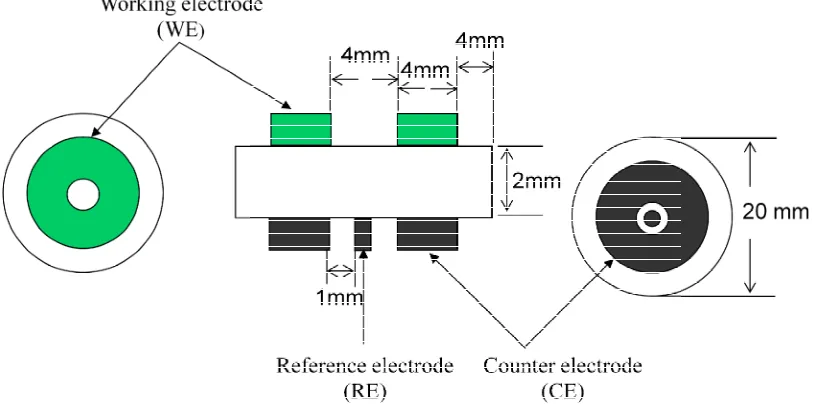
The fabrications and characterization methods/techniques of the solid oxide cells used for high temperature electrolysis will be described in this chapter. Thick YSZ electrolyte supported cells were fabricated in three-electrode geometry, and the fabrication of air electrode (anode in SOECs) was kept identical throughout this thesis. Therefore, the focus was on the cathode materials and processes and SOECs with different cathodes were prepared and tested. General steps for cathode SOEC preparation and testing will be depicted in this Chapter with detailed information mentioned in following chapters.
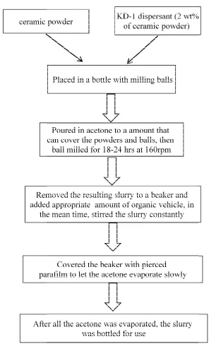
2.1 General recipe for screen-printing ink preparation
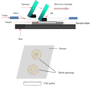
Screen-printing is a well-known approach for solid state electrode and/or electrolyte fabrication in solid oxide cells [1-3], and the detailed procedures will be described in single cell preparation in later part.
Chapter
Fig. 2.1Flow chart of preparing screen
The inks prepared as explained (Cr0.5Mn0.5)O3-δ/8 mol.% Y and LSCM / (Gd0.1Ce0.9)O materials as well as (La0.8
Chapter 2: Methods and techniques
Flow chart of preparing screen-printing ink
The inks prepared as explained above include NiO/YSZ mixture, (La
8 mol.% Y2O3stabilized ZrO2(abbreviated as LSCM/YSZ hereinafter)
)O1.95 (denoted as GDC hereinafter) composites as cathode
0.8Sr0.2)MnO3 / Sc stabilized zirconia (LSM/ScSZ in short
![Fig. 1.2 Shares of energy sources in total global primary energy supply in 2008 [2]](https://thumb-us.123doks.com/thumbv2/123dok_us/8679251.378037/22.595.107.496.323.526/shares-energy-sources-total-global-primary-energy-supply.webp)

![Fig. 2.15 Diagram of the key components of a scanning electron microscope [19]](https://thumb-us.123doks.com/thumbv2/123dok_us/8679251.378037/75.595.160.439.446.714/fig-diagram-key-components-scanning-electron-microscope.webp)


