rsos.royalsocietypublishing.org
Research
Cite this article:Rollinson AN, Williams O.
2016 Experiments on torrefied wood pellet: study by gasification and characterization for waste biomass to energy applications.R. Soc. open sci.3: 150578.
http://dx.doi.org/10.1098/rsos.150578
Received: 27 October 2015 Accepted: 26 April 2016
Subject Category:
Engineering
Subject Areas:
energy/chemical engineering/ mechanical engineering
Keywords:
gasification, biomass, torrefaction, waste to energy, kinetics, grindability
Author for correspondence:
Andrew N. Rollinson
e-mail:[email protected]
Electronic supplementary material is available at http://dx.doi.org/10.1098/rsos.150578 or via http://rsos.royalsocietypublishing.org.
Experiments on torrefied
wood pellet: study by
gasification and
characterization for waste
biomass to energy
applications
Andrew N. Rollinson and Orla Williams
Department of Engineering, University of Nottingham, Energy Technologies Building, Innovation Park, Triumph Road, Nottingham NG7 2TU, UK
Samples of torrefied wood pellet produced by low-temperature microwave pyrolysis were tested through a series of experiments relevant to present and near future waste to energy conversion technologies. Operational performance was assessed using a modern small-scale downdraft gasifier. Owing to the pellet’s shape and surface hardness, excellent flow characteristics were observed. The torrefied pellet had a high energy density, and although a beneficial property, this highlighted the present inflexibility of downdraft gasifiers in respect of feedstock tolerance due to the inability to contain very high temperatures inside the reactor during operation. Analyses indicated that the torrefaction process had not significantly altered inherent kinetic properties to a great extent; however, both activation energy and pre-exponential factor were slightly higher than virgin biomass from which the pellet was derived. Thermogravimetric
analysis-derived reaction kinetics (CO2 gasification), bomb
calorimetry, proximate and ultimate analyses, and the Bond Work Index grindability test provided a more comprehensive characterization of the torrefied pellet’s suitability as a fuel for gasification and also other combustion applications. It exhibited significant improvements in grindability energy demand and particle size control compared to other non-treated and thermally non-treated biomass pellets, along with a high calorific value, and excellent resistance to water.
2
rsos
.ro
yalsociet
ypublishing
.or
g
R.
Soc
.open
sc
i.
3
:1
50578
...
1. Introduction
Biomass is a potentially sustainable energy source only in certain circumstances: where new plant growth
equals the rate at which it is removed (hence maintaining the atmospheric CO2balance) and where no
fossil fuels have been used in fertilization, processing and transportation. For this reason, in a hierarchy of options related to the sustainable applications of biomass, locally sourced waste (such as low or negative value forestry residue) is considered to be at the top and dedicated energy crops are at the
bottom [1]. Dedicated bio-energy crops are primarily supplied to large centralized power stations, where
due to market demands, the biomass is dried in fan-assisted ovens [2,3], transported long distances (often
from different continents) [4], and almost always pelletized [5], all of which undermine its sustainability
credentials. Utilization of locally sourced biowaste for energy however—currently part of a directive to avoid landfill—necessitates only short transportation distances because of the close proximity to end use. As this resource is a by-product of sustainable land management, no petrochemical fertilizers need be used in its culture, and because of the relatively low volumes required, passive drying (seasoning) is also
feasible [1].
Small-scale downdraft gasification is a technology that has been used for over a century to generate
electricity and provide motive power from locally sourced waste biomass [6–11]. Gasifiers provide
energy on demand so battery storage is unnecessary; and there is no working fluid, so the systems offer
improved efficiencies compared to traditional combustion/steam turbine generators [7]. Furthermore,
NOxand particulate emissions are reportedly lower from gasifier engines, likely due to the way that the
engine is adjusted to cater for this type of fuel [12,13]. The likelihood of dioxin production in a gasifier
is less well defined, but recent tests found that 30–60% of the biomass chlorine content remained in the
char, and that dioxin precursor formation was inhibited by the restricted O2levels inherent within the
process [14].
Interest in gasification has recently returned and small-scale systems are now considered to have an
expanding niche market [15]. This is due to a number of factors: the desire to reduce greenhouse gas
emissions, obtain future energy security and manage waste; but equally because gasification can supply energy independent of seasonal or diurnal weather variations, and provide reliable energy in parts of the world that are off grid or subject to intermittent grid outages. Along with this, the technology is modular,
scale-able and repairable ‘in the field’ [16,17].
In theory, anything solid and carbonaceous can be gasified, and therefore converted to energy at point
of use. Yet, the technology is not currently at this stage, as the following extract relates [18, p. 15]:
One hundred years of gasification research and commercial applications have clearly shown that the key to successful gasification is a gasifier specially designed for a particular fuel. It is of paramount importance that the physical and chemical characteristics of the fuel do not change significantly.
One reason that gasifiers are not presently generic waste conversion systems is that the feedstock needs to be robust and retain its form inside the reactor to ensure adequate heat and gas transfer
[19,20]. If this feedstock falls apart due to moisture absorbance or attrition, then gas circulation inside
the reactor will be inhibited and the product will be overly contaminated with tar and particulates
[7,20]. Pelletization is used to homogenize the fuel supplied to other energy conversion technologies and
improves feeding characteristics. But whereas large-scale combustors and small-scale biomass boilers benefit from pelleted feedstock, gasifiers cannot use this type of pressure compacted reconstituted fuel. Standard commercial wood pellets, made from sawdust for example, swell when coming into contact
with water each time the gasifier is shut down [21]. This was not mentioned in one recent study where a
previously empty gasifier—a precursor to the model used in this study—was run with wood pellet, then emptied afterwards—a completely impractical way of operating a closed-top gasifier as it necessitates a
full reactor clean out after every shut-down [22]. Feedstock physical properties also determine internal
mass transfer such as its ability to flow rather than ‘bridge’ within the hopper and auger feeder [6]. It is
for these reasons that the potential of gasification has yet to be fulfilled.
Torrefaction has been suggested as a possible pre-treatment method to improve the durability of
reconstituted or non-woody biowaste to make it useable for gasification applications [23,24]. For
bio-wastes to be used as biofuels, they cannot contain heavy metals or halogenated organic compounds
[25], and the same requirements are necessary for thermally treated materials. If successful, torrefaction
could markedly increase gasifier system uptake by making use of a greater variety of biomass waste.
3
rsos
.ro
yalsociet
ypublishing
.or
g
R.
Soc
.open
sc
i.
3
:1
50578
...
reduces its moisture content (hence therefore increases calorific value) and also imparts a texture that is
more akin to coal [24]. Despite this, no published works appear to have reported actual tests to prove or
disprove the efficacy of torrefied wood pellet in a downdraft gasifier, nor are there any available reports on torrefied pellet gasification reaction kinetics.
Studying the underlying reaction kinetics of specific thermal decomposition reactions is important as it permits elucidation of both the energy requirement and reaction rate—the chemical rather than physical considerations of reactor engineering. This has specific relevance to a gasifier system, because it helps to understand how to overcome the present inflexibility with respect to feedstock heterogeneity
[6,13,26,27].
At present, torrefied biomass pellets are also attractive to other energy technologies. In this context, in addition to the better handling and storage properties, one of the main drivers for torrefaction is
to improve feedstock grindability, e.g. how easily the pellet will yield to mechanical stress [28]. This
is important for larger applications where in addition to the pre-processing already described (when
supplied to centralized power station combustion burners), the pellets are ultimately pulverized [29],
thus imposing an additional energy demand and further reducing both efficiency and overall process sustainability. For biomass to be used in a pulverized fuel burner, the standard mill classifier setting
is 1 mm [30,31]. Other types of industrial energy systems also require pulverized feedstocks, such as
entrained flow gasifiers [32]. While no standard grindability tests exist for biomass, the two main coal
grindability tests of Hardgrove Grindability Index (HGI) [33,34] and Bond Work Index (BWI) [35] have
been used for characterization. The HGI test is based on Rittinger’s theory that ‘the work done in
grinding is proportional to the new surface produced’ [36], and lower HGI values indicate a material
that is harder to grind. BWI is based on Bond’s theory that ‘the net energy required in comminution
is proportional to the total length of the new cracks formed’ [29], and lower BWI values indicate less
resistance to milling. Ohligeret al.[37] found that the improvement in grindability depended on the
degree of torrefaction, and the use of HGI alone could provide misleading results. Williamset al.[38]
used the standard HGI and BWI test to analyse a range of biomass samples and found that thermal
pre-treatments do significantly improve the grindability of biomasses. Van Essendelftet al.[39] developed
a hybrid work index to analyse the grindability of torrefied pine chips and found that it was useful in assessing torrefaction and potentially correlated with industrial scale grinding energy.
Particle size analysis is also often used as an indicator of biomass grindability. Satpathyet al.[40]
used microwave irradiation (which involves shorter residence times and permits lower temperatures) to torrefy wheat and barley straw in a batch process. They analysed the particle-size distributions
as per Bridgemanet al. [41] to assess grindability and saw a significant improvement in grindability
through torrefaction, along with the creation of a more hydrophobic pellet. Ariaset al. [42] also used
particle size distribution analysis to assess the grindability of torrefied eucalyptus chips (less than
5 mm) and also observed an improvement in grindability. Phanphanichet al. [43] torrefied pine chips
and used energy consumption and particle size to quantify the impact of torrefaction on grindability. Specific energy consumption required for grinding reduced dramatically with an increase in torrefaction
temperatures, along with the mean particle size of the ground samples. Repellinet al. [44] also noted
a reduction in particle size for wood chips torrefied in a pilot kiln. Adapa et al. [45,46] used steam
explosion to torrefy barley, canola oat and wheat straw and found increased particle densities, reduced specific energy consumption, and reduced particle size and bulk density as a result of torrefaction. For
straw, the electrical demand of microwaves is around 1.3 MJ kg–1, with the heat and conversion loss of
electricity to thermal energy at around 42% [47], and torrefied biomass retains 75–95% of its original
energy content [48]. From a techno-economic perspective, torrefied pellets offer cost savings over wood
pellets as a coal replacement fuel. Despite slightly higher production costs, torrefied pellets have a cost price of 9.8 USD/GJ for torrefied pellets compared with 12.8 USD/GJ for wood pellets, and are one of
the most cost-effective options for CO2mitigation [49].
However, most of these studies focus on the torrefaction of coarse feed materials prior to densification.
As Temmermanet al. noted [50], most biomass grinding studies focus on non-densified samples, and only
a limited number focus on the grindability of densified products, which are the products most commonly
comminuted in pulverized fuel power stations [28].
4
rsos
.ro
yalsociet
ypublishing
.or
g
R.
Soc
.open
sc
i.
3
:1
50578
...
2. Material and methods
2.1. Materials
The torrefied pellets were produced using a proprietary process of microwave-induced pyrolysis in a continuous rotating bed reactor operating at around 175°C with a residence time of 15 min. Pellets were 6 mm diameter cylinders of average 5–15 mm length, formed from coniferous timber waste (saw
dust;figure 1a). These were assessed in comparison to conventional untreated woody biomass chips,
conventional torrefied pellet and untreated commercial biomass pellets. For gasification experiments,
the wood chip was standardized to European specification P45 [25]. This comparator sample was
produced from drum chipped mixed coniferous trees, acquired from the Midlands region of the UK (Nottinghamshire Ecofuels). Seasonal time of felling was unknown, other than within six months of
supply and use (figure 1b).
2.2. Gasifier system
A 10 kW Power Pallet gasifier from GEK All Power Labs (USA) was used for experimentation. This
comprised a conventional Imbert-style downdraft reactor (with 3throat diameter) supplemented with
electronic controls and pre-heating process adaptations (figure 2). The system was designed for
small-scale off-grid electricity production from wood chips, with feedstock size tolerances of 1.3≤cm≤3.8,
and with less than 10% fines. The feedstock, once loaded into the hopper, was fed to the reactor by an automated 7 cm diameter smart auger, activated using an internal fuel-level paddle switch sensor. Within the auger channel (the drying bucket), there occurs non-contact heat exchange with post-reactor gases, and then secondly, non-contact heat exchange with engine exhaust in the ‘pyrocoil’ region situated directly above the gasification reactor. From the pyrocoil onwards, feedstock falls through the reactor under gravity. The system operates under slight negative pressure created during steady-state operation via a three cylinder Kubota spark ignition engine (although at start-up and shut-down, electric fan blowers are used to generate suction and to divert dirty gases from the engine to a flare stack via a manually operated valve). Sub-stoichiometric airflow enters the centre of the reactor and creates a small zone of combustion within (again via engine suction). The amount of air is sufficient only to provide heat for development of drying, pyrolysis and reduction zones and to create autothermal
operation. For an explanation of downdraft gasifier thermochemistry and mechanics, see [6,16,51,52].
Thermocouples are placed at the base of the combustion zone and bottom of the reduction zone (upper
and lower ‘T/C’ infigure 2), and there are two pressure sensors: one located at the combustion zone
and the other after the reduction zone, to provide real-time readouts of temperature and pressure
across the reactor. The resultant determination of pressure difference (Pratio) is linked to an intelligent
grate shaker which activates when Pratio falls below a set point. Gas is cleaned by a cyclone and a
packed bed filter comprising replaceable wood chips, left over fines and a polishing stage of two oiled foam inserts.
The gas engine is connected to a generator rated at 10 kWeand the system provides power on demand,
meeting variations in external load by a governor controlled throttle. This consequently increases or decreases the rate of air (and gas) flow through the reactor. For these tests, a bespoke distribution box
was provided (Distribution Zone, UK) and the electrical load was dumped into two 2 kWerated resisters
(Cressall, UK).
2.3. Gasification product analysis
Producer gas analyses were extracted post filter (figure 2) and measured every 5 s using an online
Gasboard 3100P by Wohun Cubic with inbuilt pump and adjustable flow meter set at 1 l min−1.
Non-destructive analytical cells determined CO, CO2, CH4and CnHmby dual beam NDIR, and H2by thermal
conductivity. Raw gas was extracted post filter and passed through a water trap (filled with 350 ml of room temperature tap water), carbon filter and 0.3 µm polypropylene fibre F3000 (by CDK). The analyser was calibrated using high-purity bottled gases by STG.
5
rsos
.ro
yalsociet
ypublishing
.or
g
R.
Soc
.open
sc
i.
3
:1
[image:5.522.64.458.322.560.2]50578
...
(b) (a)
Figure 1.(a) Torrefied pellet and (b) P45 mixed wood chip used for gasification.
clean producer gas
biomass in gas
analyser
packed bed filter
control unit
data logging hopper
1
2 engine
air
gas engine
4 3
gasifier air in
five air nozzles
5 P
7
T/C
T/C P
producer gas out ash grate
6
gravity feed of biomass to reactor 10 kW
generator
exhaust out
Figure 2.Ten kilowatt Power Pallet gasifier and schematic. (1) Drying bucket, (2) auger, (3) pyrocoil, (4) insulation, (5) combustion zone,
(6) reduction zone, (7) cyclone particle separator.T/C, thermocouple andP, pressure sensors relay to control unit.
2.4. Gasification feedstock physical properties
Single species wood chip was also obtained from the same supplier (as §2.1), and represented the constituent parts of the mixed chip used in gasification experiments. The samples included both
heartwood and bark. Three softwood species were assayed: European larch (Larix decidua), silver birch
(Betula pendula) and Corsican pine (Pinus nigrassp. laricio).
6
rsos
.ro
yalsociet
ypublishing
.or
g
R.
Soc
.open
sc
i.
3
:1
50578
...
reduced in size using a Retch ZM200 centrifugal rotor mill with a 0.50 mm cut stainless steel ring sieve. This produced a particle size for the biomass of 80% less than 0.25 mm.
2.4.1. Proximate analysis
Proximate analysis was by thermogravimetry using a TA Instruments Q500, with samples placed into
a clean platinum pan (10 mm diameter×2 mm depth). Experimentation was at constant 1 bar pressure
using two high-purity gases: 99.98% N2 and air, both from Air Products UK. Data were logged every
0.8 s and saved on a personal computer. From room temperature, the samples 24≤mg≤35 were heated
to 110°C under N2flow (of 120 ml min−1) at 10°C, and then held for 10 min. Temperature was increased
to 900°C at a rate of 20°C ml min−1, and then held for 15 min. The carrier gas was then switched to air at
a flow rate of 120 ml min−1.
2.4.2. Ultimate analysis
A CE Instruments Flash EA1112 analyser was used to determine C, H, N and (by balance) O
elemental compositions. Samples and standards were weighed (1.6≤mg≤3.8) for wood chip species,
and (3.0≤mg≤3.3) for torrefied pellet, into tin capsules and then ignited inside the instrument at 900°C
using oxygen over a copper oxide catalyst. Product gas was passed over electrolytic copper to remove
O2and magnesium perchlorate to remove H2O en route to a gas chromatography column and infrared
detector. Helium was used as carrier gas. The analyses were repeated using a standard (2,5-bis(5-tert
-butyl-2-benzo-oxazol-2-yl)thiophene) for elemental determination, weighed to a comparable value for each of the three types of sample.
2.4.3. Calorific value
An IKA C5001 bomb calorimeter was used, set to dynamic method. Two tablets (combined weight 1.0092 g) of known calorific value were used. Benzoic acid (pelletized) IKA C723 was a pre-experimental standard. Pellets were made from the biomass samples by compressing the shredded materials, using a Greasby Specac manual press and a 13 mm stainless steel die. Compression was at 10 tonne pressure.
2.4.4. Reaction kinetics
Using the TA Q500 instrument set up as previously (§2.4.1), a standardized methodology for downdraft
gasification kinetics was used to determine parameters associated with reaction (2.1) [51]:
C+O2→CO2 H= −394 kJ mol−1. (2.1)
The reactivity of the sample under CO2flow (2.1) was calculated using the common formula [53–57]:
k= 1 w0
dw
dt. (2.2)
From the derivative term of equation (2.2),wis the change in mass over time (t), in this case 12–24 s.w0
iswt−wdaf: the difference between the mass at the midpoint of the time interval, e.g. point at a tangent
to the mass loss curve (wt) and end of reaction stage mass (wdaf).
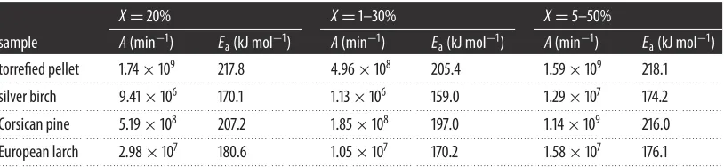
Gasification reactivity values were plotted against percentage conversion over the (2.1) stage. Kinetic values were then calculated based on conversions at 20%, between 1 and 30%, and between 5 and 50%.
Extent of conversion was calculated fromX=(wi−wt)/(wi−wash), wherewi is the initial mass at the
start of the reaction stage.
Kinetic parameters of (2.1) were determined by assuming that the reaction obeys the first-order Arrhenius equation, and by taking logs of both sides such that equation (2.3) takes the form of a linear
equation on a Cartesian plot of ln(k) against 1/T, withEa/Ras the slope andAas they-axis intercept:
k=Aexp
−Ea
RT
, (2.3)
whereEa=activation energy, in J mol−1;A=frequency factor, in units of collisions s−1;R=universal gas
constant, in J K−1mol−1;T=temperature, in kelvin.
2.4.5. Hygroscopicity
7
rsos
.ro
yalsociet
ypublishing
.or
g
R.
Soc
.open
sc
i.
3
:1
50578
...
measuring cylinders of 600 ml capacity were each filled with around 200 ml (116.51±0.05 mg) of each
pellet type. Simultaneously, 100 ml of room temperature tap water was poured into each of these and volume change was recorded at time intervals: 1 min, 2 min, 10 min, 1 h, 2 h, and 6 h. Moisture content of each pellet was measured before and after the tests.
2.4.6. Grindability
The BWI for the torrefied pellets was determined using a dry grinding test in a standardized testing
machine, the Bico Ball Mill [58]. The mill contained 285 steel balls of total weight 20.13 kg with a drum
size of 305 mm in diameter by 305 mm in length which rotates at a constant speed of 70 r.p.m. The average
diameter of 100 measured pellets was used as 80% passing feed particle size (F80) for the torrefied pellets
in accordance with BS EN ISO 17829 [59]. The BWI test used 700 ml of dry sample (as per [60]) run for
100 revolutions in the mill, following which the contents were sieved to a set target equilibrium sieve
size (P1). While the normal BWI test is defined on ascertaining the energy consumption in comminuting
material to pass 100 µm, the target sizes used in full-scale coal mills for biomass and coal are different and based on the burner requirements. The target size was set to 1 mm based on pulverized fuel burner
requirements for biomass [30,61]. The sieved fines were weighed and placed to one side, and new product
was added to the oversized milled material to bring it back to its original weight. The new number of revolutions required was calculated from the results of the previous test to produce sieve undersize
equal to 1/3.5 of the total charge of the mill. This process was repeated until the gram per revolution (G)
reached a constant value for a minimum of three cycles. A full sieving analysis was performed on the
last three cycles and the 80% passing size of the product (P80) was determined to calculate the BWI. The
general form of the BWI equation is
W=10Wi×
1
√
P80 −
1
√
F80
, (2.4)
whereW is the work input andWi is the BWI (both kWh t−1), which expresses the resistance of the
material to crushing and grinding.F80 andP80are the 80% passing size of the feed and product (µm),
respectively.Wican therefore be found through the following equation:
Wi= 44.5
P10.23
×G0.82×
10
√
P80 −
10
√
F80
, (2.5)
whereP1is the closing sieve size (µm) andGis the grindability (net g rev−1).
3. Results and discussion
3.1. Characterization
3.1.1. Physical properties
The physical properties of the different feedstocks (table 1) reveal that the low-temperature microwave
torrefied pellet had an increased fixed to volatile carbon ratio, and higher calorific value than the virgin wood from which it was derived. This phenomenon has previously been reported as being a consequence
of the torrefaction process [23,24]. Bulk density was also 115% greater than the mixed wood chip. High
calorific value and bulk density are beneficial properties for all fuel applications, as they equate to more energy per unit volume, and mean greater economy in fuel use, transportation and storage space. The relevance of fixed to volatile carbon ratio is discussed in §3.2.2.
3.1.2. Reaction kinetics
The mass loss stages of biomass thermal decomposition have previously been well explored [20]. From
figure 3, the second stage of thermal decomposition (onset approx. 22 min, up to completion at approx. 70 min) evidences pyrolysis. This reveals, and enables quantification of, the extent and rate of volatile
release. The fixed to volatile carbon ratios seen here are in accordance with previous studies [51]. The
mass loss at approximately 88 min occurs from the switch to 100% CO2and therefore indicates the (2.1)
8
rsos
.ro
yalsociet
ypublishing
.or
g
R.
Soc
.open
sc
i.
3
:1
[image:8.522.153.372.41.227.2] [image:8.522.56.468.299.392.2]50578
...
110 900
800 700 600 500 400 300 200 100 0 100
90 80 70 60 50
mass (%)
temperature (°C)
40 30 20 10 0
0 20 40 60 time (min)
80 100 120 140 temperature
Corsican pine silver birch torrefied pellet European larch
Figure 3.Results of thermogravimetric analysis for torrefied pellet and a range of virgin wood species.
Table 1.Proximate and ultimate analyses, gross calorific values and bulk density of samples (daf, dry ash free).
ultimate analysis (% daf) proximate analysis (% dry basis) sample N C H O volatiles fixed carbon ash
calorific value (MJ kg−1)
bulk density g l−1
torrefied pellet 0.18 46.08 5.57 52.71 81.85 17.51 0.64 22.1 490
. . . .
silver birch 0.11 49.28 6.05 53.37 85.5 13.9 0.6 18.4 227a
. . . .
Corsican pine 0.19 48.91 6.31 47.17 83.6 15.7 0.7 19.0
. . . .
European larch 0.00 49.03 5.99 46.99 86.4 12.4 1.2 18.3
. . . .
aMixed P45 wood chip.
out of the reactor. This char creates a ‘reduction zone’ and its purpose is to promote (2.1), and other
reducing reactions [6,20]. No data exist on the optimum depth of this reduction zone, but although there
are other influencing parameters, fixed-bed gasifiers are proved to operate well with feedstock fixed
to volatile carbon ratios for those shown for the torrefied pellet intable 1[6,19]. Differences between the
species here would therefore influence subsequent reactor bed dynamics by the extent of carbon available which would ultimately affect the quality of gas produced.
Although fixed-bed gasifiers are autothermal and therefore do not require external heat input to maintain equilibrium, knowledge of relative activation energies is still practically important for reactor sizing and to optimize fuel conversion efficiency. The torrefied pellet exhibited a linear trend on a
Cartesian Arrhenius plot congruent to those of other wood species (figure 4). This is not surprising
considering that its molecular composition was likely one or all of the same species, in particular pine, which predominates as a softwood building material and which most closely compares to the torrefied
pellet in this study’s results (see alsotable 2). These results suggest that the torrefaction process had
not significantly altered inherent kinetic properties to a great extent, despite both activation energy and pre-exponential factor being just slightly higher than virgin pine.
Plots of reactivity as a function of conversion for the torrefied pellet match well with the theoretical
predictions of the random pore model [62], which represents particle thermolysis as developing by a
random overlapping of cylindrical voids that grow as a function of temperature from the initial pores.
The random pore model introduces a structural parameter term (ψ) which defines the initial physical
properties of the particle, and which determines the shape of the reactivity versus conversion curve. Increasing value for the structural parameter is associated with reactivity versus conversion curve
convexity, which derives from progressive particle porosity [63]. These values (shown infigure 5) were
calculated from the peak of conversion as a function of reactivity using equation (3.1) [64]:
Ψ= 2
9
rsos
.ro
yalsociet
ypublishing
.or
g
R.
Soc
.open
sc
i.
3
:1
[image:9.522.152.372.41.233.2] [image:9.522.151.374.293.486.2] [image:9.522.61.468.568.662.2]50578
...
0.5 0 –0.5 –1.0 –1.5 –2.0
ln(
k
)
–2.5 –3.0 –3.5 –4.0
0.00084 0.00088 silver birch
silver birch
European larch European larch Corsican pine
Corsican pine torrefied pellet
torrefied pellet
1/T(K)
0.00092
Figure 4.Kinetic parameter ln(k) as a function of 1/Tfor all samples after isothermal experiments. Plots shown were taken over mass
loss stage 20% conversion. All plots 0.95≤R2≤0.96.
0.8
0.7 2.2£y£3.2 800
825 850 875 900 925 950 0.6
0.5 0.4 0.3
reactivity (min
–1)
0.2 0.1 0
0 0.4 0.5 0.6 0.7 0.8 0.9 1.0 conversion (%)
0.3 0.2 0.1
Figure 5.Reactivity as a function of conversion for Rotawave torrefied wood pellet. Data points shown selected at 0.01% conversion
interval. Peak fitting atR2=0.99 was used to identifyχ
max.ψcorrect to±0.1.
Table 2.Activation energies and pre-exponential factors at varying conversion levels.
X=20% X=1–30% X=5–50%
sample A(min−1) E
a(kJ mol−1) A(min−1) Ea(kJ mol−1) A(min−1) Ea(kJ mol−1)
torrefied pellet 1.74×10⁹ 217.8 4.96×10⁸ 205.4 1.59×10⁹ 218.1
. . . .
silver birch 9.41×10⁶ 170.1 1.13×10⁶ 159.0 1.29×10⁷ 174.2
. . . .
Corsican pine 5.19×10⁸ 207.2 1.85×10⁸ 197.0 1.14×10⁹ 216.0
. . . .
European larch 2.98×10⁷ 180.6 1.05×10⁷ 170.2 1.58×10⁷ 176.1
. . . .
Sixth-order polynomial curves were fitted. These torrefied pellet curve shapes and values forψclosely
match those previously reported for all European softwoods, and again in particular Corsican pine [51].
10
rsos
.ro
yalsociet
ypublishing
.or
g
R.
Soc
.open
sc
i.
3
:1
50578
...
regard to porosity development. The relevance of which is that porosity determines the availability of surface sites for chemical reactions, and therefore a gasifier should be able to tolerate switching between chipped wood and torrefied pellet in this respect.
3.1.3. Hygrosopicity
When compared against standard miscanthus pellet (initial moisture 1.6%), the miscanthus pellet had swollen by 50% after 1 min, 100% after 2 min and 150% after 1 h, whereas the torrefied pellet (initial moisture 0.2%) remained unchanged. After 24 h, the torrefied pellet was removed from the water, and it had not changed in volume or weight, whereas the miscanthus pellet had completely lost all its shape and form. This is a highly advantageous generic property of the torrefied pellet in terms of handling and storage for all fuel applications as it reduces the need for measures to protect against moisture ingress. For all bio-energy applications, moisture absorbance greatly reduces the calorific value of a fuel, because
of the high parasitic enthalpy demands of H2O inside the reactor. For small-scale downdraft gasification,
this property has extra significance, as it would overcome the need for a full clean out of the reactor bed after each shut-down due to pellet disintegration.
3.2. Gasification tests
3.2.1. Wood chip
Downdraft gasification technology has a rich history, and it is proven to work on chipped or chopped
wood feedstock, although it is a fact that there are many instances of system failures [6]. It was not
therefore the aim to test whether or not the system would work with wood chip, rather that the results should provide a comparative appraisal of qualitative and quantitative performance. Notwithstanding this, no peer reviewed literature could be found that reported the efficacy of this type of modern gasifier. Long duration stable operation of the gasifier was achieved but only by screening the wood chip (7 mm cut) of fines. Excessive pressure drop across the reactor otherwise occurred. Sieving of the wood chip was also necessary to remove excessively large or elongate pieces which were found to cause both bridging and auger jams. This was laborious work, and highlights the need for feedstock uniformity. It also evidences the lack of market structure at present with respect to the availability of suitable feedstock for gasifiers, as the P45 grade was the closest match to the system design specification. Sustainable woody biomass waste that is produced from arboriculture at the local scale in Europe is presently chipped for size reduction and ease of removal rather than for use as an energy commodity, and in particular one which is suitable for gasification (low volume of fines and narrow range of chip sizes). But, this is not an insurmountable challenge, and 80 years ago when gasification use was at its peak, some countries actually had a well-developed national infrastructure for feedstock supply through garages
and filling stations [6]. The absence of such an infrastructure at present would however hold back current
system penetration.
At switch on, the system took approximately 30 min to reach satisfactory temperature for engine ignition (around 850°C for the top thermocouple and 700°C for the thermocouple at the base of the
reduction zone). The system ran well at output levels of 4 kWe, and 2 kWe. Once the engine was
operational, temperature remained stable (other than small oscillations) and in the expected range for
all runs, and consequently, gas composition of H2and CO was relatively stable also (figure 6).
The particulate matter collected from the gas analyser water trap for all runs was of 48±9.8 mg Nm−3.
For long-term producer gas supply to an internal combustion engine, the maximum concentration of tar
and particulates is suggested as being 50 mg Nm−3[6,65]. Online gaseous hydrocarbons (CnHm) were
detected in the range of 0≤ppm≤10 at steady-state experimentation, and so considered negligible.
Water will be expected to capture all the particulates, gravimetric tars, polar tars, and up to 39% of
non-polar tars [66], but the values obtained here must still be considered as a minimum. The higher
than recommended fraction of small pieces (fines included) contained within the feedstock can perhaps explain why the particulate and tar concentration was around the maximum suggested value, due to
how small pieces inhibit free gas transfer within the reactor [20].
11
rsos
.ro
yalsociet
ypublishing
.or
g
R.
Soc
.open
sc
i.
3
:1
[image:11.522.152.371.40.222.2]50578
...
25
1200
1000
800
600
400
200
0 20
15 CO
temp. (top) temp. (bottom) CH4
CO2 H2
producer gas v
o
l(%)
reduction zone temperature (°C)
10
5
0
0 2000
time (s)
3000
Figure 6.Producer gas output from P45 mixed wood chip, and reduction zone temperatures. System running at steady state providing
4 kWe, representative of all experiments. CnHmvalues (not shown) were 2≤ppm≤5. Temperature standard deviation about the 2 h
mean=19°C (top) and 22°C (bottom). Gas analyses accuracy less than or equal to±2% full scale, less than or equal to 2 repeatability.
3.2.2. Torrefied pellet
Preliminary experiments were run to populate the reactor combustion and reduction zones with torrefied pellet char. To this end, the reactor chamber was loaded with lumpwood charcoal in size range of
1.5≤cm≤5 (from Big Green Egg, UK) to just above the air inlet (top of combustion zone). The hopper
was removed and the torrefied pellet was observed as it was fed through the auger system into the pyrocoil. The angle of the hopper feeding channel was 30° from vertical, and the pellet was seen to have excellent flow characteristics (electronic supplementary material, S1), due to its cylindrical shape and smooth, hard surface texture. This is beneficial for all automated feeding systems. For small-scale gasification, it has the added bonus of alleviating common issues of bridging and channelling.
The gasifier reactor was then run for 2 h at steady 2 kWeload, to move the torrefied pellet through to
the combustion and reduction zones. Close to the end of this preliminary test, there was a build up of
internal pressure notifiable by repeated activation of thePratioalarm sensor. This was manually quietened
since the duration of the preliminary test was almost complete.
The first full test started well, with instant ignition and a very clear blue flame from the flare stack evidencing a gas free of tar and soot. Before the engine could be brought in-line, reactor temperature
quickly reached above safe operating limits (T>1050°C) and was still climbing. Afterwards, upon
examination of the cooled reactor, a high concentration of pellet dust was found inside—the likely cause
of the high pressure while running the preliminary test (figure 7). High temperature can be beneficial
inside a downdraft gasifier as the desired reactions are promoted. The rate of (2.1) in particular drops
rapidly below 800°C [51]. Yet, too high a temperature can lead to spreading combustion which therefore
decreases the size of the reduction zone. In addition, very high temperatures can cause internal damage
to the air nozzles [7,20], and also lead to the formation of fused deposits inside the reactor [67]. The
reactor was cleaned out and re-filled with the torrefied pellet char (minus the fines).
Numerous repeated attempts were made with the same result: rapid increases in temperature, along with increased reactor pressure drop. Sometimes the combustion zone would ignite, but the flame in the flare stack would not, being very smoky and extinguishing itself regardless of gas and air mixing levels. These occurrences indicated that packing in the pyrocoil was loose, but that the reduction zone/throat was densely packed with pellet dust. This proved to be correct each time the reactor was cleaned out.
12
rsos
.ro
yalsociet
ypublishing
.or
g
R.
Soc
.open
sc
i.
3
:1
[image:12.522.154.367.40.202.2]50578
...
Figure 7.Torrefied pellet extracted from the combustion zone of Power Pallet gasifier after failed experimental run.
With regard to the high reactor temperatures, this was undoubtedly due to the high calorific value and energy density of the torrefied pellet. Both highly attractive properties, but for a downdraft gasifier set up to operate within a relatively rigid range of feedstock moisture, the torrefied pellet could not be accommodated. This gasifier system did not have in-built adjustments to permit the required changes, and indeed it highlights the limitations that presently exist with this technology. Even a modern system must still be considered a rigid technology where once set up to operate at a certain feedstock parameter, there is limited flexibility to tolerate feedstock variations which then result in excessive maintenance
requirements, and lower than specified performance [16,24,26]. Of note however is that other downdraft
gasifiers are gravity rather than auger fed, with the feedstock hopper situated directly above the
reactor [16]. Chemically, the torrefied pellet would appear to be a highly attractive gasifier feedstock,
and one which could be able to make use of a variety of otherwise unsuitable waste biomass materials.
This, along with the likely lower NOx/dioxin emissions, overall efficiency and financial gains, and
greater CO2 mitigation potential, makes the combined technologies in many ways far more attractive
for future commercial development than traditional grate combustion. The small size of the pellets may be problematic long term as even without being subjected to attrition in the auger channel, the size was at the low end of design tolerance for these systems. It would not seem overtly challenging to produce a larger sized, torrefied pellet, and a useful future study would then be to re-attempt these tests in a standard gravity fed downdraft gasifier. Notwithstanding the above, the torrefied pellet friability under attritional stress is a beneficial attribute for many combustion applications.
3.3. Grindability
Owing to the hydrophobic nature of the torrefied pellets, it was not possible to obtain the common
particle size distribution of disintegrated pellets [68]. Thus, it was not possible to use the particle size
comparison as a matrix of biomass grindability in comparison to several previous studies [40–44]. The
HGI test uses small masses or volumes [33,34,41,69], and thus for biomass pellets, the BWI test offers
a grindability test with a more representative volume (700 ml compared to 50 ml), allows for variable target sizes, and for the pellet diameter to be used as the initial feed size.
The BWI (Wi) expresses the resistance of the material to grinding to a specified product size, and the
higher the value ofWi, the more difficult the material is to grind to the required product size. The work
inputWgives the grinding power required by the mill as described. These results are illustrated intable 3
accompanied by the results of a previous study on the application of the BWI test on a range of densified
biomass pellet [38]. The low-temperature microwave torrefied pellet performed favourably in the BWI
test compared with untreated and other thermally treated biomass with aWiof 25 kWh t−1. Several
non-treated biomass pellets exhibited mill choking (mixed wood, miscanthus and sunflower pellets), which
resulted in very highWivalues (413, 426 and 366 kWh t−1, respectively), but this was not observed for the
torrefied pellet. The torrefied pellet performed on a par with another commercially produced torrefied
pellet (denoted as traditional torrefied pellet) which had aWiof 16 kWh t−1. This traditional torrefied
13
rsos
.ro
yalsociet
ypublishing
.or
g
R.
Soc
.open
sc
i.
3
:1
[image:13.522.56.486.81.268.2]50578
...
Table 3.BWI results for microwave torrefied pellets.F80, 80% passing feed size;P80, 80% passing product size;G, grindability per
revolution;RF, final revolution count;Wi, BWI;W, work input;H, gross calorific value on dry basis;W/H, work input-gross calorific value ratio.
material source F80(µm) P80(µm) G(g rev−1) RF Wi(kWh t−1) W(kWh t−1) H(kJ g−1) W/H(%)
this study
. . . .
torrefied pellets 5970 881 2.015 62 25 5 22.1 0.08
. . . .
source [32]
. . . .
wood pellets 8400 786 0.053 2141 413 102 20.4 1.80
. . . .
miscanthus pellets 6290 811 0.057 2168 426 96 18.6 1.86
. . . .
sunflower pellets 8620 764 0.059 1699 366 93 20.2 1.66
. . . .
eucalyptus pellets 8390 757 0.340 411 87 22 19.8 0.40
. . . .
steam exploded pellets 5910 355 0.283 556 64 26 20.0 0.46
. . . .
traditional torrefied pellets 8000 758 2.655 60 16 4 21.8 0.07
. . . .
olive cake 3712 590 0.202 390 136 34 19.3 0.63
. . . .
La Loma coal 2709 77 0.664 242 23 22 30.0 0.26
. . . .
than the steam exploded pellets, which had a much higherWiof 64 kWh t−1. This is due to the product
particle size of the steam exploded pellet being very small (P80of 355 µm), while the torrefied pellets had
P80sizes much closer to non-treated biomasses (758 µm for the traditional torrefied pellet and 881 µm for
the microwaved torrefied pellet). As with the traditional torrefied pellet, the milling energy required to reduce the pellets to the target particle size of sub 1 mm was a low percentage of the calorific value of the microwave torrefied pellet at 0.08%.
4. Conclusion
This study assessed the performance of a torrefied wood pellet produced by low temperature microwave pyrolysis through a series of experiments to assess its suitability as an energy feedstock. Tests with a modern small-scale downdraft gasifier in comparison to wood chip at standard specification were combined with characterization relevant to other industrial fuel applications.
The torrefied pellet was found to have the following beneficial attributes as an energy feedstock: 1. Relatively high calorific value and high bulk density in comparison to virgin wood chip. 2. High water repellence, which would allow it to be stored outdoors or indoors in high moisture
areas. For downdraft gasification, this would overcome issues of steamed disintegration. 3. Significant improvement in grindability compared to other non-treated and thermally treated
biomass pellets. The low grinding energy and comparable particle size with non-treated biomass pellets in the BWI test suggest good particle size control which would make it a suitable fuel for pulverized fuel power stations, or fluidized bed gasification systems.
4. The torrefaction process did not appear to have altered inherent kinetic properties; however,
both activation energy and pre-exponential factor (for CO2 gasification) were slightly higher
than original virgin biomass.
5. Flow and gravity feeding properties were found to be excellent.
The torrefied pellet proved to be practically unsuitable as a feedstock in this modern gasifier: 6. Its high calorific value and energy density resulted in an excessively high reactor temperature. 7. The auger feeder was the main detrimental component, as it partially crushed the pellet to a
fine powder. This in turn blocked the reactor core. In general handling of the pellet and while observing its flow inside the hopper, no dust was observed to form.
8. For the above reasons, steady-state operation could not be achieved with the 10 kWe Power
14
rsos
.ro
yalsociet
ypublishing
.or
g
R.
Soc
.open
sc
i.
3
:1
50578
...(points 1, 2, 4 and 5). Consequently, there is a strong case for continuing research in torrefied pellet as a gasifier fuel, and for research with a gravity fed downdraft gasifier. The problems encountered were those commonly associated with downdraft gasifiers which are not set up for this type of feedstock, and which do not permit the necessary means of simple operator adjustment.
Data accessibility. Data available from the Dryad Digital Repository:http://dx.doi.org/10.5061/dryad.nn8pj.
Authors’ contributions. A.N.R. conceived and completed all gasification experiments, and all experiments with torrefied pellet reaction kinetics, and hygroscopicity, along with analysis and writing these sections of the manuscript. O.W. conceived and completed all BWI grindability experiments, along with analysis and writing these sections of the manuscript. Both authors contributed to conception, completion and analysis of the characterization results. This final version of the manuscript was subject to correction and approval by both authors.
Competing interests.The torrefied pellet was purchased from a commercial company (Rotawave Ltd, UK). The gasifier was also purchased from a commercial company (All Power Labs, USA).
Funding. This study was financed by EPSRC grant no. EP/J000361/1—Rural Hybrid Energy Enterprise Systems. Acknowledgements. Thanks to the research groups of Prof. Michèle Clarke and Prof. Colin Snape at University of Nottingham for hosting these experiments.
References
1. Kreschmer B, Watkins E, Baldock D, Allen B,
Keenleyside C, Tucker G. 2011Securing biomass for
energy—developing an environmentally responsible industry for the UK now and into the future, pp. 1–79. London, UK: Institute for European Environmental Policy.
2. Forestry Commission. 2011Wood chip drying. Forest
Research, pp. 1–11. Delamere, UK: Forestry Commission.
3. McGovern RE. 2007Report on trials of farm grain
dryers for wood chip moisture reduction. SAC Consultancy Services Division report, pp. 1–9. Craibstone, Aberdeen.
4. H.M. Government. 2012UK bioenergy strategy, pp.
1–86. London, UK: Department of Energy and Climate Change.
5. OFGEM. 2012 Annual Sustainability Report Dataset
[online]. Seehttps://www.ofgem.gov.uk/
publications-and-updates/annual-sustainability-report-2011-2012(accessed 11 September 2015).
6. Kaupp A. 1981State of the art for small-scale gas
producer-engine systems, pp. 1–282. First published by the German Appropriate Technology Exchange (GATE). Golden, CO: Biomass Energy Foundation Press.
7. Food and Agriculture Organization. 1986Woodgas
as an engine fuel, Forestry Paper 72, pp. 1–139. Rome, Italy: United Nations.
8. LaFontaine H, Zimmerman FP. 1989Construction of
a simplified wood gas generator for fueling internal combustion engines in a petroleum emergency, pp. 1–66. Washington, DC: Federal Emergency Management Agency.
9. Faaij A, van Doorn J, Curvers T, Waldheim L, Olsson E, van Wijk A, Daey-Ouwens C. 1997 Characteristics and availability of biomass waste and residues in
the Netherlands for gasification.Biomass Bioenerg.
12, 225–240. (doi:10.1016/S0961-9534(97)00003-2)
10. Mamphweli SN, Meyer LE. 2009 Implementation of the biomass gasification project for community empowerment at Melani village, Eastern Cape,
South Africa.Renew. Energ.34, 2923–2927.
(doi:10.1016/j.renene.2009.06.011)
11. Maniatis K, Millich E. 1998 Energy from biomass and waste: the contribution of utility scale biomass
gasification plants.Biomass Bioenerg.15, 195–200.
(doi:10.1016/S0961-9534(98)00052-X)
12. Sridhar G, Sridhar HV, Dasappa S, Paul PJ, Rajan NKS, Mukunda HS. 2005 Development of producer
gas engines.Proc. IMechE Part D219, 423–438.
(doi:10.1243/095440705X6596)
13. Hamilton JE, Adams JM, Northrop WF. 2014 Particulate and aromatic hydrocarbon emissions from a small-scale biomasss gasifier-generator
system.Energ. Fuel.28, 3255–3261.
(doi:10.1021/ef500437z)
14. Björkman E, Strömberg B. 1997 Release of chlorine from biomass at pyrolysis and gasification
conditions.Energ. Fuel.11, 1026–1032. (doi:
10.1021/ef970031o)
15. Asadullah M. 2014 Barriers of commercial power generation using biomass gasification gas: a review.
Renew. Sust. Energ. Rev.29, 201–215.
(doi:10.1016/j.rser.2013.08.074)
16. Jain BC. 2000 Commercialising biomass gasifiers:
Indian experience.Energy Sustain. Dev.4, 72–82.
(doi:10.1016/S0973-0826(08)60255-0)
17. Stassen HE. 1995Small-scale biomass gasifiers for
heat and power: a global review. World Bank technical paper no. 296, pp. 1–88. Washington, DC: The World Bank.
18. Kaupp A. 1984Gasification of rice hulls: theory and
praxis. Eschborn, Germany: Deutsche Gesellschaft fur Technische Zusammenarbeit (GTZ) GmbH. 19. Overend R. 1979 Gasification—an overview. In
Reftofit 79Proc. Workshop on Air Gasification, Seattle, WA, 2 February 1979, SERI/TP-49-183, The Solar Energy Research Institute, Section 3.0.
20. Reed T, Das A. 1988Handbook of biomass downdraft
gasifier engine systems, pp. 1–148. Golden, CO: Solar Energy Research Institute.
21. All Power Labs. 2014 Biomass Feedstock
Requirements [online]. Seehttp://wiki.gekgasifier.
com/w/file/fetch/80364911/Chapter%202_ %20Biomass%20Feedstock%20Requirements.pdf
(accessed 20 September 2015). 22. Wolff D, Walsh E, McDonnell K. 2013 Practical
experience with woody biomass in a down-draft
gasifier.J. Technol. Innov. Renew.2, 47–52.
(10.6000/1929-6002.2013.02.01.6)
23. Deng J, Wang G-J, Kuang J-H, Zhang Y-L, Lou Y-O. 2009 Pretreatment of agricultural residues for
co-gasification via torrefaction.J. Anal. Appl. Pyrol.
86, 331–337. (doi:10.1016/j.jaap.2009.
08.006)
24. Prins MJ, Ptasinski KJ, Janssen FJJG. 2006 More efficient biomass gasification via torrefaction.
Energy31, 3458–3470.
(doi:10.1016/j.energy.2006.03.008)
25. British Standards. 2010BS EN14961 : 2010 solid
biofuels—fuel specifications and classes—part 1: general requirements, pp. 1–54. London, UK: BSI. 26. Kirkels FA, Verbong JPG. 2011 Biomass gasification:
still promising? A 30-year global overview.Renew.
Sust. Energ. Rev.15, 471–481.
(doi:10.1016/j.rser.2010.09.046)
27. Ruiz JA, Juarez MC, Morales MP, Munoz P, Mendivil MA. 2013 Biomass gasification for electricity generation: review of current technology barriers.
Renew. Sust. Energ. Rev.18, 174–183.
(doi:10.1016/j.rser.2012.10.021)
28. Tumuluru JS, Sokhansanj S, Hess JR, Wright CT, Boardman RD. 2011 A review on biomass torrefaction process and product properties for
energy applications.Ind. Biotechnol.7, 384–401.
(doi:10.1089/ind.2011.7.384)
29. Loo V, Koppejan SJ. 2008 Co-combustion. InThe
handbook of biomass combustion and co-firing, pp. 203–248. London, UK: Earthscan.
30. Esteban LS, Carrasco JE. 2006 Evaluation of different strategies for pulverization of forest biomasses.
Powder Technol.166, 139–151.
(doi:10.1016/j.powtec.2006.05.018)
31. Tamura M, van de Kamp W. 2001 Characteristics of alternative fuel for blend with pulverised coal. In
6th Conf. on Technologies and Combustion for a Clean Environment, Lisbon, Portugal, 9–12 July, pp. 585–589.
32. Minchener AJ. 2005 Coal gasification for advanced
power generation.Fuel84, 2222–2235.
(doi:10.1016/j.fuel.2005.08.035)
33. ASTM. 2012D409 / D409M-12 Standard test method
15
rsos
.ro
yalsociet
ypublishing
.or
g
R.
Soc
.open
sc
i.
3
:1
50578
...34. The British Standards Institution. 1995BS 1016-112:
1995 Methods for analysis and testing of coal and coke—Part 112: determination of Hardgrove grindability index of hard coal, pp. 1–12. London, UK: BSI.
35. Bond FC. 1952 The third theory of comminution.
Trans. AIME(Mining)193, 484–494.
36. Von Rittinger PR. 1867Lehrbuch der
Aufbereitungskunde, pp. 1–626. Berlin, Germany: Ernst and Korn.
37. Ohliger A, Förster M, Kneer R. 2013 Torrefaction of beechwood: a parametric study including heat of
reaction and grindability.Fuel104, 607–613.
(doi:10.1016/j.fuel.2012.06.112)
38. Williams O, Eastwick C, Kingman S, Giddings D, Lormor S, Lester E. 2015 Investigation into the applicability of Bond Work Index (BWI) and Hardgrove Grindability Index (HGI) tests for several biomasses compared to Colombian La Loma coal.
Fuel158, 379–387. (doi:10.1016/j.fuel.2015.05.027) 39. Van Essendelft DT, Zhou X, Kang BS-J. 2013
Grindability determination of torrefied biomass
materials using the Hybrid Work Index.Fuel105,
103–111. (doi:10.1016/j.fuel.2012.06.008)
40. Satpathy SK, Tabil LG, Meda V, Naik SN, Prasad R. 2014 Torrefaction of wheat and barley straw after
microwave heating.Fuel124, 269–278.
(doi:10.1016/j.fuel.2014.01.102)
41. Bridgeman TG, Jones JM, Williams A, Waldron DJ. 2010 An investigation of the grindability of two
torrefied energy crops.Fuel89, 3911–3918.
(doi:10.1016/j.fuel.2010.06.043)
42. Arias B, Pevida C, Fermoso J, Plaza MG, Rubiera F, Pis JJ. 2008 Influence of torrefaction on the
grindability and reactivity of woody biomass.Fuel
Process. Technol.89, 169–175.
(doi:10.1016/j.fuproc.2007.09.002)
43. Phanphanich M, Mani S. 2011 Impact of torrefaction on the grindability and fuel characteristics of forest
biomass.Bioresource Technol.102, 1246–1253.
(doi:10.1016/j.biortech.2010.08.028)
44. Repellin V, Govin A, Rolland M, Guyonnet R. 2010 Energy requirement for fine grinding of torrefied
wood.Biomass Bioenerg.34, 923–930.
(doi:10.1016/j.biombioe.2010.01.039)
45. Adapa P, Tabil L, Schoenau G. 2010 Physical and frictional properties of non-treated and steam exploded barley, canola oat and wheat straw
grinds.Powder Technol.201, 230–241.
(doi:10.1016/j.powtec.2010.03.038)
46. Adapa P, Tabil L, Schoenau G. 2011 Grinding performance and physical properties of non-treated
and steam exploded barley, canola, oat and wheat
straw.Biomass Bioenerg.35, 549–561.
(doi:10.1016/j.biombioe.2010.10.004)
47. Luque R, Menéndez JA, Arenillas A, Cot J. 2012 Microwave-assisted pyrolysis of biomass
feedstocks: the way forward?Energy Environ. Sci.2,
5481–5488. (doi:10.1039/c1ee02450g)
48. Ciolkosz D, Wallace R. 2011 A review of torrefaction
for bioenergy feedstock production.Biofuels
Bioprod. Biorefin.5, 317–329. (doi:10.1002/
bbb.275)
49. Koppejan J, Sokhansanj S, Melin S, Madrali S. 2012
Status overview of torrefaction technologies. IEA Bioenergy Task 32, pp. 1–54. Enschede, The Netherlands: Proceed Biomass B.V. 50. Temmerman M, Jensen PD, Hébert J. 2013 Von
Rittinger theory adapted to wood chip and pellet
milling, in a laboratory scale hammermill.Biomass
Bioenerg.56, 70–81.
(doi:10.1016/j.biombioe.2013.04.020)
51. Rollinson AN, Karmakar MK. 2015 On the reactivity
of various biomass species with CO2using a
standardised methodology for fixed-bed
gasification.Chem. Eng. Sci.128, 82–91.
(doi:10.1016/j.ces.2015.02.007)
52. Bridgewater AV. 2003 Renewable fuels and
chemicals by thermal processing of biomass.Chem.
Eng. J.91, 87–102.
(doi:10.1016/S1385-8947(02)00142-0)
53. Ahmed II, Gupta AK. 2010 Pyrolysis and gasification of food waste: syngas characteristics and char
gasification kinetics.Appl. Energ.87, 101–108.
(doi:10.1016/j.apenergy.2009.08.032)
54. Asadullah M, Zhang S, Min Z, Yimsiri P, Li CZ. 2010 Effects of biomass char structure on its gasification
reactivity.Bioresource Technol.101, 7935–7943.
(doi:10.1016/j.biortech.2010.05.048)
55. Cetin E, Moghtaderi B, Gupta R, Wall TF. 2004 Influence of pyrolysis conditions on the structure
and gasification reactivity of biomass chars.Fuel
83, 2139–2150. (doi:10.1016/j.fuel.2004.
05.008)
56. Di Blasi C. 2009 Combustion and gasification rates of
lignocellulosic chars.Prog. Energy Combust. Sci.35,
121–140. (doi:10.1016/j.pecs.2008.08.001)
57. Tancredi N, Cordero T, Rodríguez-Mirasol J,
RodrÍguez JJ. 1996 CO2gasification of eucalyptus
wood chars.Fuel75, 1505–1508.
(doi:10.1016/0016-2361(96)82641-X)
58. Bond FC. 2007 The Bico Ball Mill [online]. Seehttp://
www.bicoinc.com/assets/BallMill_
OperatingManual.pdf(accessed 6 July 2015).
59. The British Standards Institution. 2014Draft BS EN
ISO 17829 Solid biofuels—determination of length and diameter of pellets, pp. 1–10. London, UK: BSI.
60. Warren Spring Laboratory. 1962Grindability test
procedure and ball-mill size selection(Mineral processing information notes No.3), pp. 1–18. London, UK: Warren Spring Laboratory. 61. Freeman MC, O’Dowd WJ, Brown TD, Hargis Jr RA,
James RA, Plasynski SI, Walbert GF, Lowe AF, Battista Jr JJ. 2000 Pilot-scale air toxics R&D assessment of creosote-treated and PCP-treated wood cofiring for pulverized coal utility boiler
applications.Biomass Bioenerg.19, 447–456.
(doi:10.1016/S0961-9534(00)00055-6)
62. Bhatia SK, Perlmutter DD. 1980 A random pore model for fluid-solid reactions: 1. Isothermal, kinetic
control.AIChE J.26, 247–254.
(doi:10.1002/aic.690260308)
63. Ahmed II, Gupta AK. 2011 Kinetics of woodchip char
gasification with steam and carbon dioxide.Appl.
Energ.88, 1613–1619.
(doi:10.1016/j.apenergy.2010.11.007)
64. Seo DK, Lee KL, Kang MW, Hwang J, Yu T-U. 2012
Gasification reactivity of biomass chars with CO2.
Biomass Bioenerg.34, 1946–1953.
(doi:10.1016/j.biombioe.2010.08.008)
65. The British Standards Institution. 2012BS EN
16126 : 2012 BSI—Solid biofuels.Determination of particle size distribution of disintegrated pellets, pp. 1–16. London, UK: BSI Group. 66. Agus F, Waters PL. 1971 Determination of the
grindability of coal, shale and other minerals by a
modified Hardgrove machine method.Fuel50,
405–431. (doi:10.1016/0016-2361(71)90029-9)
67. Parikh PP, Bhave AG, Kapse DV, Ketkar A, Bhagivat AP. 1988 Design and development of a wood gasifier for I.C. engine applications—new
approach for minimization of tar. InResearch in
thermochemical biomass conversion(eds AV Bridgwater, JL Kuester), pp. 1071–1087. London, UK: Elsevier Applied Science.
68. Phuphuakrat T, Namioka T, Yoshikawa K. 2011 Absorptive removal of biomass tar using water and
oily materials.Bioresource Technol.102, 543–549.
(doi:10.1016/j.biortech.2010.07.073)
69. Miles TR, Miler Jr TR, Baxter LL, Bryers WR, Jenkins BM, Oden LL. 1996 Boiler deposits from firing
biomass fuels.Biomass Bioenerg.10, 125–138.