— 1 —
Effect of the changed electrolytic cell on the current efficiency in FFC
Cambridge process
Meilong Hu1*, Qu Zhengfeng1, Bai Chenguang1,Di Hu2, George Z. Chen2*
1.College of Materials Science and Engineering, Chongqing University, China, 400044
2.Department of Chemical and Environmental Engineering, University of Nottingham Ningbo China, 315100
*Corresponding author, E-mail:[email protected]; [email protected]
Abstract: Low current efficiency of the FFC Cambridge process made it no obvious
advantages in cost compared with the traditional process to produce metals. Effect of the
changed electrolysis cell on the current efficiency has been studied. Put the cathode into an
alumina tube with a hole can efficiently avoid short circuit and the cathode contaminated by
carbon produced from graphite anode. The results show that the current efficiency can be
improved greatly by reducing the electric field intensity in the electrolysis cell. The high
background current is mainly caused by the electronic conductivity in the electrolysis cell.
Otherwise, pollution of the cathode is avoided, the depletion of the anode sharply decreases
and the deoxidation of the samples greatly improve when using the improvement electrolysis
cell.
Keywords: FFC Cambridge process, current efficiency, changed electrolytic cell
1. Introduction
In metallurgy field, extracting metals from their oxides by FFC Cambridge process
attracted a lot of attention due to its valuable advantages, for example, short process,
environment friendly and metal powder obtained directly. Most of metals have been obtained
— 2 —
development of the process is limited because of its high cost, namely low current efficiency.
There are many reasons caused the low current efficiency of the FFC process. The first is the
original nature of the metal oxides. Some metal oxides have good electric conductivity. The
electro-deoxidization of these oxides is much easier than those have poor electric
conductivity, liking semiconductor metal oxides. The second factor effected the current
efficiency is the anode material. Normally, to accelerate the oxygen ions leaved from the
electrochemical system, graphite rod always used as the anode in FFC process. Carbon
powder, dropped from the graphite rod due to the reaction between oxygen ions and anode or
produced by the reaction O2-+CO
2=CO32-(anode) and CO32-+4e-=C+3O2- (cathode), floats on
the surface of the molten salt for the buoyancy. The cathode, anode and carbon powder can
form the current circuit with the outside circuit, which made both of the resistance of cyclic
circuit and the current efficiency of the electrochemical deoxidization decrease. The third
factor is the impurities included in molten salt and metal oxides. There is no any chemical
that is totally purity. These impurities will exhaust the electric energy during electrochemical
deoxidization caused the current efficiency reducing. Otherwise, the metal products are
probably contaminated due to much lower decomposition voltage of the impurities. The main
factor influenced the current efficiency maybe is the electronic conductivity 7). Many kinds of
multivalent anodic ions in the molten salt, liking anodic ions of the molten salt, anodic ions of
the metal oxides, anodic ions of the impurities, will bring electronic conductivity for their
transfer in site or valence.
Previous work has investigated the current efficiency for the FFC Cambridge process as a
function of the electrolysis time, sintering conditions used for the cathode metal-oxide pellet,
cell voltage, the molten salt temperature, and the anodic variables8-12). The results of the
studies show that the current efficiency can be improved by optimization of the electrolysis
time, sintering conditions, cell voltage, the temperature and the inert anode. Although the
current efficiency also can be improved using the inert anode, the cost of the anode prepared
is the limited step. However, the effect of the changed electrolysis cell on the current
efficiency has not been explored. In this paper, through changing the electrolysis cell to study
the effect of the cell on the current efficiency in FFC Cambridge process.
— 3 —
Two kinds of electrolytic cells with two electrodes were used to measure the effect of them
on the current efficiency of the FFC Cambridge process. The changed cell used is shown
schematically in Fig.1. And using an alumina tube with a hole(diameter 8.0 mm) trapped the
cathode in it to change the traditional FFC electrolysis cell. The catholic metal oxide can face
to face with the graphite anode through the hole. Above edge of the hole is lower than the
molten salt surface about 10mm. The lower edge is higher than the bottom of the crucible
about 15mm.
Fig.1. the changed electrolysis cell
Titanium oxide powder of 98% specified purity was selected as the oxide precursor. The
titanium oxide was uniaxially pressed, at 6~7 MPa using a 7 mm diameter, into 0.4g
preformed pellets. These pellets were subsequently sintered at 1173K for 2h, resulting the
pellets had sufficient mechanical strength for wrapping on the metal wire. Then the pellet was
attached to the steel rod served as cathode, and the graphite rod was used as the anode.
A dense alumina crucible of 100 mm internal diameter and 100 mm height was then placed
inside the vertical tubular reactor. The crucible contained CaCl2 salt. The water-cooled upper
end of the reactor was sealed with a stainless steel cover with silicone-sealed feed. The sealed
reactor system was vacuumed and then was continually flushed through with argon gas.
Repeat 3 times. The reactor was then heated at a constant rate of 3 K/min by the furnace until
a temperature of the target temperature was reached with argon flow of 120 ml/min. The
carbon powder floated on the molten salt can be found. Using the molybdenum cathode
collected the carbon and removed from the electrolysis cell.
After the operating temperature had been reached, the system was left to stabilise for 1h.
Thereafter, the titanium oxide pellet sintered was slowly lowered into the electrolyte (when
using the alumina tube put the tube into the salt slowly and then placed the cathode in the
tube slowly). The graphite rod was then immersed to the molten salt. A constant voltage of
3.1 V was applied between the anode and the cathode.
Electro-deoxidation was terminated after 6 h, and the electrodes were removed from the
melt into the part of the reactor. After the reactor was cooled the electrodes were removed
from it and washed with water to remove salt in the electrolysed sample.
These procedures were repeated using the alumina tube to allow direct comparison with
— 4 — 3. Results and discussion
3.1Constant voltage electrolysis
Fig.2Current changes with time at constant voltage of 2.8V with tube and without tube (a) titanium oxide electrolysis, weight of sample is 0.42g, electrolytic temperature is 1173K for 6h (b) chromium oxide electrolysis, weight of sample is 1.0g, electrolytic temperature is 1083K for 6h.
The current efficiency of the constant electrolysis can be described as equation (1). Here,
𝑄𝑇 is the theoretic electric quantity to electrochemical deoxidize of the cathodic metal oxide. 𝑄𝐴 is the actual electric quantity exhausted during deoxidization of the cathodic metal oxide, showed as equation (2). C and t are the current and the electrolysis time, respectively.
From equation (1) it can be seen that the actual electric quantity is smaller and the current
efficiency is bigger. Fig.2 shows that the shape and changes of the current curve are same
with tube and without tube. But the area enclosed by the current curve with tube is much
smaller and the background current is lower than that without tube. It means that the current
efficiency increases when the cathode is trapped in the alumina tube. It is difficult to confirm
the background current. The actual current efficiency can be calculated by the assistant of the
oxygen content in metal obtained in the cathode. When the cathode trapped in the alumina
tube the current efficiency is almost twice to the traditional electrolytic cell. Due to electric
field has the great effect on the electronic conductivity, decreasing its intensity can reduce the
electronic conductivity. One advantage of using the tube with the hole can cut most of the
electric field between cathode and anode. The electric field just exist in the area of the hole
on the tube. The electronic conductivity greatly decreases for the electric field intensity
weakening. So the background current decreases and the current efficiency of the process
increases. The other is cut off the current circuit caused by the carbon powder floating on the
surface of the molten salt between two electrodes. Due to the hole on the tube is lower than
the surface of the molten salt. The carbon powder cannot enter the tube to contaminate the
product. It can reduce the current depletion and increase the current efficiency. As a result the
whole current efficiency increases when the alumina tube is wrapped on the cathode. The
electrodes pollution are also reducing.
Current efficiency: 𝜂 = 𝑄𝑇
𝑄𝐴 (1)
Actual electric quantity: QA = ∫ 𝐶 𝑑𝑡 (2)𝑡2
— 5 — 3.2Effect of the changed cell on cathode
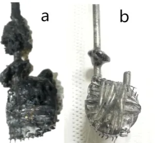
Fig.3 Cathodes electrolysed without tube(a) and with tube(b) using chromium oxide
The final product–metal leaves on the cathode through the FFC Cambridge process
using metal oxides as the precursor. So the cathode has a close relationship with the quality
of the final product. Figure 3 is the cathodes electrolysed without tube(Fig.3a) and with
tube(Fig.3b), which are the appearance taken from the salt and cooled in the top of the
furnace. It shows that the final product is wrapped by the carbon powder and polluted heavily
when the cathode put into the molten salt directly. However, the cathode electrolysed with
tube is cleaner. The tube, which encloses the cathode, can prevent the carbon dropped off
from the anode closing to the cathode. In fact, the carbon, produced during electrolysis, has
two obvious drawbacks for electrolysis. Firstly, carbon powder will float to the cathode and
cover it caused the final metal product polluted. Secondly, the carbon floating on the surface
of the molten salt connects the cathode and the anode caused the current efficiency decreased.
The cell with the tube can increase the current efficiency of the electrolysis and prevent the
final product from polluting.
3.3Effect of the changed cell on anode
The graphite anode is always used in the FFC Cambridge process to remove oxygen ions
from the electrolysis cell. The carbon can easily react with the oxygen ions formed CO or
CO2 gases released from the electrochemical deoxidization system. But due to the
sub-reaction and the depletion the carbon powder cause the current efficient decrease and the
cathode contaminate. The anodes, after the constant voltage electrolysis with tube, show as
Fig.4a(side faced the hole) and Fig.4b(off side faced the hole). The depletion of the anode,
using the tube during electrochemical deoxidization in FFC Cambridge process, obviously
extenuate. The back of the anode facing the hole of the tube almost does not consume. From
Fig.4a the area of the graphite anode faced the hole is much reacted than the other zone. But
the area on the anode close the bottom of the crucible has much bigger holes whatever with
tube and without tube, which maybe produced by the diffusion of the oxygen ions from the
lower edge of the alumina tube to the anode. This results show that the alumina tube limit the
oxygen ions diffusion from cathode to anode maybe cause the current efficiency decrease.
— 6 —
respectively. The diameter of the anode obviously become small and the graphite depletion is
very severely compared with the electrolysed anode with tube. The anode depletion is much
lower than that without tube. These results show that the impurities and the electronic
conductivity spend much energy during electrochemical deoxidization of FFC Cambridge
process caused the current efficiency decrease. The alumina tube used in the FFC Cambridge
process decrease the electronic conductivity largely by cutting down the electric field
intensity. The depletion of the anode obviously lightens and the oxygen in metal reduces.
Fig.4 Anode electrolysed with tube. Fig.5 Anodes electrolysed with tube and without tube.
(a. side faced the hole, b. off side faced the hole) (a. off side with hole, b. off side without hole)
4. Conclusions
Decreasing the electric field intensity between the cathode and the anode by using a tube
wrapped the metal oxide cathode can not only increasing the current efficiency but also
reducing the anode depletion, decreasing the cathode contamination and decreasing the
oxygen content in the final metal. The current efficiency of the constant voltage electrolysis
with tube increases morn 10% than that without tube. Although the current efficiency
increases when use the alumina tube in the cathode, the diffusion of the oxygen ions may be
restricted in the tube and limit the current efficiency further increasing. The results of the
constant voltage electrolysis show that the electronic conductivity is the main factor caused
the high background current in FFC Cambridge process. How to effectively control the
electronic conductivity is the key point to increase the current efficiency in this process.
Acknowledgement
Support for this work was provided by the National Natural Science Foundation of China
through contract NO. 51404044, 51674054 and Open Foundation of State Key Laboratory of
Vanadium and Titanium Resources Comprehensive Utilization of China.
REFERENCES
1) X. Y. Yan and D. J. Fray: Metall Mater Trans B. 33 (2002) 685-693. 2) P. C. Pistorius and D. J. Fray: J S Afr I Min Metall. 106 (2006). 3) K. S. Mohandas and D. J. Fray: T Indian I Metals. 57 (2004) 579-592.
— 7 —
6) M. Bertolini, L. Shaw, L. England, K. Rao, J. Deane and J. Collins: Key Eng Mat. 436 (2010) 75-83. 7) M. Ma, D. Wang, W. Wang, X. Hu, X. Jin and G. Z. Chen: Journal of Alloys and Compounds. 420
(2006) 37-45.
8) Q. Xu, L. Q. Deng, Y. Wu and T. Ma: Journal Of Alloys And Compounds. 396 (2005) 288-294. 9) C. Schwandt, D. T. L. Alexander and D. J. Fray: Electrochim Acta. 54 (2009) 3819-3829. 10) K. T. Kilby, S. Jiao and D. J. Fray: Electrochim Acta. 55 (2010) 7126-7133.
— 8 — Captions List
Fig. 1 Caption The schematic of the changed electrolytic cell
Fig. 2 Caption Current changes with time at constant voltage of 2.8V with tube and without tube
(a) titanium oxide electrolysis, weight of sample is 0.42g, electrolytic temperature is 1173K for 6h
(b) chromium oxide electrolysis, weight of sample is 1.0g, electrolytic temperature is 1083K for 6h.
Fig.3Caption Cathodes electrolysed without tube(a) and with tube(b) using chromium oxide
Fig.4 Caption Anode electrolysed with tube (a. side faced the hole, b. off side faced the hole)
— 9 —
[image:9.595.96.501.274.425.2]Fig.1 The schematic of the changed electrolytic cell
Fig. 2 Caption Current changes with time at constant voltage of 2.8V with tube and without tube
(a) titanium oxide electrolysis, weight of sample is 0.42g, electrolytic temperature is 1173K for 6h
(b) chromium oxide electrolysis, weight of sample is 1.0g, electrolytic temperature is 1083K for 6h.
[image:9.595.229.389.543.690.2]— 10 —
Fig.4 Anode electrolysed with tube.
(a. side faced the hole, b. off side faced the hole)