http://wrap.warwick.ac.uk
Original citation:
Jhumka, Arshad and Leeke, Matthew (2011) The early identification of detector locations
in dependable software. In: 2011 IEEE 22nd International Symposium on Software
Reliability Engineering, Hiroshima, Japan, 29 Nov - 2 Dec 2011. Published in: 2011
IEEE Proceedings of 22nd International Symposium on Software Reliability Engineering
pp. 40-49
Permanent WRAP url:
http://wrap.warwick.ac.uk/42362
Copyright and reuse:
The Warwick Research Archive Portal (WRAP) makes this work by researchers of the
University of Warwick available open access under the following conditions. Copyright ©
and all moral rights to the version of the paper presented here belong to the individual
author(s) and/or other copyright owners. To the extent reasonable and practicable the
material made available in WRAP has been checked for eligibility before being made
available.
Copies of full items can be used for personal research or study, educational, or not-for
profit purposes without prior permission or charge. Provided that the authors, title and
full bibliographic details are credited, a hyperlink and/or URL is given for the original
metadata page and the content is not changed in any way.
Copyright statement:
“© 2011 IEEE. Personal use of this material is permitted. Permission from IEEE must be
obtained for all other uses, in any current or future media, including reprinting
/republishing this material for advertising or promotional purposes, creating new
collective works, for resale or redistribution to servers or lists, or reuse of any
copyrighted component of this work in other works.”
A note on versions:
The version presented here may differ from the published version or, version of record, if
you wish to cite this item you are advised to consult the publisher’s version. Please see
the ‘permanent WRAP url’ above for details on accessing the published version and note
that access may require a subscription.
The Early Identification of Detector Locations in Dependable Software
Arshad Jhumka and Matthew Leeke
Department of Computer Science University of Warwick Coventry, West Midlands United Kingdom, CV4 7AL
{arshad, matt}@dcs.warwick.ac.uk
Abstract—The dependability properties of a software system are usually assessed and refined towards the end of the software development lifecycle. Problems pertaining to software dependability may necessitate costly system redesign. Hence, early insights into the potential for error propagation within a software system would be beneficial. Further, the refinement of the dependability properties of software involves the design and location of dependability components called detectors and correctors. Recently, a metric, called spatial impact, has been proposed to capture the extent of error propagation in a software system, providing insights into the location of detectors and correctors. However, the metric only provides insights towards the end of the software development life cycle. In this paper, our objective is to investigate whether spatial impact can enable the early identification of locations for detectors. To achieve this we first hypothesise that spatial impact is correlated with module coupling, a metric that can be evaluated early in the software development life cycle, and show this relationship to hold. We then evaluate module coupling for the modules of a complex software system, identifying modules with high coupling values as potential locations for detectors. We then enhanced these modules with detectors and perform fault-injection analysis to determine the suitability of these locations. The results presented demonstrate that our approach can permit the early identification of possible detector locations.
Keywords-Dependability; Detector Location; Module Coupling; Software Engineering; Spatial Impact
I. INTRODUCTION
The increasing pervasiveness of software-based computer systems has led to a corresponding increase on such software systems to provide correct and timely services at all times, i.e., we need such software systems to be dependable [1]. To develop a dependable software system, a dependability component known as a detector is typically required [2]. Two factors that impact the efficiency of a given detector component are (i) the error detection predicate that the detector implements and (ii) the location of the detector [3]. The detector location problem involves choosing a program action that needs to execute in a appropriate, i.e., safe, state, and locating the detector at that action to ensure that the state is always safe whenever the action is executed.
In general current approaches for the identification of effective detector locations are applicable only at a late stage of the software development lifecycle. Indeed, many
techniques are only applicable once a functionally correct system is available, at which point the system can be transformed to make it dependable [2] [4] [5]. A limitation of many such techniques is that they operate on a finite state representation of a software system. Other techniques that work with real-world software systems approximate the detector location problem, where a notion of impact is assessed, such that the location identification is done on a best-effort, i.e., highest impact first, basis [4] [6]. Such a notion of impact can be used to identify suitable detector locations in order to avoid locating detectors where they are not needed, in a type of cost-benefit analysis. However, there is a limitation of such techniques. The notion of impact they employ is usually investigated during the validation of a software system, which typically occurs towards the end of the software development lifecycle.
Such a metric must capture a notion of impact in order to allow for the identification of effective detector locations.
A metric, called spatial impact, that achieves the goal stated above has recently been proposed [8]. Spatial impact captures the extent of the error propagation process with respect to the modules of a software system. Broadly, it captures the number of modules that are affected whenever an error propagates throughout a system. Specifically, the spatial impact of a module is the number of modules that are affected whenever an error propagates beyond the boundary of that module. Thus, spatial impact captures (i) a notion of the extent of the error propagation process and (ii) a notion of impact on system safety, making it a suitable dynamic metric. In fact, it has been shown that modules with high spatial impact are good candidates for detector locations [9]. Spatial impact is a software metric that is evaluated at a late stage of the development lifecycle of dependable software, while module coupling can be evaluated much earlier.
To enable module coupling to be used as a guide for the identification of possible detector locations there is a need (i) to demonstrate that there exists a correlation between module coupling and spatial impact, and (ii) to show that module coupling can help to identify detectors locations early in the software development lifecycle. At this stage it is important to acknowledge that many factors impact the error propagation process, including component failure rates and operational profiles, thus it should be noted that the work presented in this paper does not intend to present a singular approach for the location of detector components.
A. Contributions
In this paper we make the following specific contributions: 1) We demonstrate a correlation between spatial impact and module coupling through the application of fault injection analysis to complex software systems. 2) We demonstrate that module coupling can used as
a guide for the location of detectors in each of the software systems under analysis.
3) We present experimental results to show that locating detectors at modules with higher coupling values has a higher impact on system dependability, i.e., we show that a significant reduction in system failures can be achieved through equipping highly coupled modules with error detectors.
B. Paper Structure
This paper is structured as follows. In Section II we provide a survey of related literature. In Section III we develop the adopted system and fault models. In Section IV we introduce the dependability and software engineering metrics used in this paper, including all metric definitions and a discussion of the intuitive relationships between them. In Section V we describe the experimental setup used to evaluate the relationships between the metrics discussed. In Section VI
we present and discuss the results of our experimentation. In Section VII we conclude this paper with a discussion of future work and a summary of what has been achieved.
II. RELATEDWORK
In this section, we discuss a range of research in software engineering metrics, with an emphasis on the origins and implications of work relating to module coupling. We then discuss software dependability metrics, focusing on the software characteristics they capture and their limitations.
A. Software Engineering Metrics
The concepts of module coupling and cohesion were first proposed by Stevens, Myers and Constantine in [10]. This work was subsequently revisited in [11], where a seven point ordinal scale for module coupling was proposed. In [12] Page-Jones defined eight levels of module coupling, where each level of coupling was characterised by the impact that interacting modules had upon factors such as maintainability, modifiability and reusability. In [13] Offutt et al. further extend this work by developing algorithms to automate the calculation of module coupling and introducing twelve levels of coupling to a allow fine-grained analysis to be undertaken. Much research has also attempted to develop and validate theoretically sound definitions of module coupling and co-hesion for specific programming paradigms and application domains, including knowledge-based, aspect-oriented and object-oriented systems [14] [15] [16].
Since the concepts associated with structured design were first communicated, a variety of definitions for coupling and cohesion have been proposed. The majority of these definitions rely upon some form of static analysis being performed upon a software system or associated design for-malisms. Indeed, in order to apply the definition of module coupling adopted in this paper it is required that source code be analysed [17]. In [18] and [19] Chidamber and Kemerer proposed and refined a well known static metric suite for object-oriented software systems, incorporating paradigm specific software metrics such as coupling between objects (CBO) and lack of cohesion of methods (LCOM). In [20] and [21] Ott and Beiman propose cohesion metrics based upon static program slices for outputs computed by a function. For an in-depth discussion and analysis of slice-based techniques for the calculation of module coupling and cohesion metrics the interested reader is referred to [22].
static approaches could not. Furthermore, in [25] Yacoub
et al. proposed a set of dynamic coupling measures that can be applied during the early software design phase, validating the approach by applying these dynamic metrics in a range of scenarios. Dynamic approaches have also been proposed for the calculation of module cohesion, with work in [26] describing a dynamic approach which defines module cohesion metrics based upon definition-use pairs in dynamic program slices.
Coupling, cohesion and other structural software metrics have been shown to be good indicators for a number of external quality attributes. For example, studies in [27] and [28] concluded that such metrics could be an indicator for fault-proneness. Furthermore, work in [29], [30] and [31] concluded that structural metrics, including coupling and cohesion, were good indicators of external quality attributes such as maintainability and reusability. However, little work has shown whether coupling can be used to capture aspects of dynamic error propagation, with [32] reaching no con-clusive results. In this paper we provide evidence to support the notion that static metrics can capture aspects of dynamic error propagation.
B. Dependability Metrics
A variety of static and dynamic dependability metrics have been proposed. Coverage and latency are two established dependability metrics that are frequently used to assess the effectiveness of detectors [33]. Further, the approach developed in [4] extended work in [34] and [35] to provide a framework for identifying vulnerabilities in software sys-tems. This framework was based upon an error permeability metric, which captures how likely errors are to propagate from a module’s input to output. However, the focus of these metrics is either signal-centric or mechanism-centric, making them irrelevant as indicators of coupling which is module-centric. In contrast to the work presented in this paper, stochastic approaches have been adopted in the analysis of error propagation for dependability enhance-ment [36] [37]. Closer to the intention of this paper, work in [38] sought to rate the criticality of software modules based on their position in a software system, whilst the focus of [39] was on dependability enhancement through consideration of interface failures. Recently, a dynamic, module-centric dependability metric, called spatial impact, was proposed, that captures error propagation properties [8]. The focus of this paper is to (i) explore the relationship between spatial impact and module coupling and (ii) use this hypothesised relationship to contribute to the early identification if locations for detector components.
III. MODELS
In this section, we present the system and fault models assumed in this paper.
A. Software model
In this paper we consider software systems to begrey box, which means that access to the source code is allowed but knowledge of functionality and structure is unavailable, i.e. white box access (for measuring software metrics) with black box knowledge. We assume a software systemSto be a tuple, consisting of a set of components,C1. . . Cn, and a
set of connections. A component Ck consists of an import
interface Ik, an export interfaceEk, a set of parametersPk
and a bodyBk.Ik represents the set of resourcesCk needs
in order to provide the set of resources specified inEk. Here
resources are generally considered to be functions, whilst an interface is a set of resources. Pk contains a disjoint set of
variables Vk and constants ck. The body Bk provides the
implementation of Ek, usingIk.
Two componentsCk andClare connected ifCk exports a
functionf toCl, i.e. a functionf required byClis provided
by Ck defines a connection between Ck and Cl. Thus, a
softwareS= (CM P, CON), whereCM P ={C1. . . Cn},
and CON = {(Ckf, Clf)}, where Ck exports a function f
toCl. WhenCk exports a functionf toCl, we say thatCk
sends a message f to Cl. We assume a special component
called ENV (read environment) that exports inputs to the software or imports output from the software. Note that the set of connections implicitly captures the module coupling aspect that we intend to investigate.
Our grey box model implies that, althoughBk,∀kis
avail-able, knowledge and understanding ofBk is not necessary.
Further, in this paper the set of connectionsCONneed not be available. This model of a software, and our grey box model fits well with software engineering practices. For example, it may be the case that a team will develop a software system, whilst a separate team will be responsible for imparting dependability and therefore may not have detailed knowledge of (Bk, CON). We also assume the software to
be functionally correct but fault-intolerant, i.e., the software satisfies its specification in the absence of faults may violate it in the presence of faults. In other words, there are no built-in detectors or correctors within the software system. Observe that measuring module coupling generally requires source code to be available but does not assume knowledge of functionality, matching the system model adopted in this paper. Henceforth, the terms “component” and “module” are used interchangeably.
B. Fault model
IV. SOFTWAREMETRICS
In this section we review the concept of module coupling and present the definition used in this paper, as well as providing a definition for spatial impact. We then present our hypothesis regarding these two software metrics.
A. Module Coupling
Module coupling captures the degree to which a given software module depends upon the other modules within a system to provide its designated services. Module coupling is recognised as a fundamental measure of good software design. Software engineers are invariably encouraged to design and implement software modules which exhibit a low degree of coupling, as sets of loosely coupled modules are widely considered to be indicative of a maintainable, reusable and comprehensible software system.
In this paper we adopt the definition of coupling proposed in [17] and republished in [41]. This definition takes into account four different types of coupling in order to quantify overall module coupling; data flow, control flow, global and environmental coupling. We now give an overview of this definition of module coupling. The interested reader is referred to [17] for an in-depth discussion of the given definition and the reasoning upon which it is based. To calculate module coupling we use the following notation:
• For data and control flow coupling, let:
– i1 = Input data parameters
– i2 = Input control parameters – u1 = Output data parameters – u2 = Output control parameters
• For global coupling:
– g1 = Global variables used as data – g2 = Global variables used as control
• For environmental coupling:
– w= Number of modules called – r= Number of modules calling
If we let m= i1+αi2+u1+βu2+g1+γg2+w+r, whereα, β, γare parameters, then module coupling, denoted byMcoupling, can be calculated as:
Mcoupling= 1/m (1)
As any module under test must be called by at least one other module the minimum value of r is 1, which in turn means that the minimum value of m is also 1. Given this, it is evident that the maximum possible value ofMcoupling,
for any α, β, γ, is 1, a value which would correspond to the loosest possible level of module coupling. We will also investigate the impact of the parametersα, β, γ on the relationship between coupling and spatial impact.
B. Spatial Impact
Given a software system whose functionality is logically distributed over a set of distinct components, the spatial impact of a variablev of componentC in a runr, denoted
σr
v,C, is the number of components whose states are changed
in rdue to a change inv. The spatial impact of a variable
v in componentC, denoted byσv,C, is defined as:
σv,C =max{σv,Cr },∀r (2)
Hence,σv,C captures the diameter of the affected area when
a variable v in a component C is corrupted. The spatial impact of a component C is obtained by considering the spatial impact of each variable in C. Thus, we define the spatial impact of a componentC, denotedσC, as:
σC=max{σv,C},∀v∈C (3)
Thus, σC captures the worst-case extent of corruption
as-sociated with component C when an internal variable is corrupted.
C. Relating Software Metrics
We now make one hypothesis regarding the correlation between coupling and spatial impact. This hypothesis will be evaluated in Section VI.
Hypothesis: Coupling captures information regarding the extent a module is integrated within the software system. On the other hand, spatial impact captures the extent to which a given module propagate errors across a system. As errors can only propagate as a result of interaction between software modules, we hypothesise that a correlation exists between spatial impact and module coupling. In particular, we hypothesise that modules with a higher (resp. lower) spatial impact will be more tightly (resp. loosely) coupled than those with a lower spatial impact.
In the remainder of this paper we apply an approach, based on fault injection, for evaluating the spatial impact metric. We then measure module coupling in order to establish a basis for the testing of the above hypothesis.
V. EXPERIMENTALSETUP
A. Target Systems
A total of 3 software systems are used as target systems in this paper. The 7-Zip and Mp3Gain target systems are used to evaluate the hypothesis stated in Section IV-C, whilst the FlightGear target system is subsequently enhanced with detectors that have been located based on module coupling. A description of each of these target systems is given below.
7-Zip (7Z):The 7-Zip utility is a high-compression archiver which supports a variety of file archiving and encryption formats [42]. This target system was chosen because it is widely-used, modular, written in C/C++ and has been developed and maintained by many different software engineers. Most source code associated with this target system is freely available under the GNU Lesser General Public License.
Mp3Gain (M3): The Mp3Gain analysis suite is an open-source volume normalisation solution for mp3 files [43]. This system is modular, written in C/C++ and has been predominantly developed by a single software engineer. All source code and resources associated with this target system are available under the GNU General Public License.
FlightGear (FG):The FlightGear Flight Simulator project is an open-source project which aims to develop an extensible yet highly sophisticated flight simulator to serve the needs of the academic and hobbyists communities [44]. This target system was chosen because it is modular, contains over 220,000 lines of C/C++ and simulates a situation where de-pendability is critical. All source code and project resources are available under the GNU General Public License.
B. Test Cases
7Z: An archiving procedure was executed in all test cases. The procedure took a set of 25 files of varying formats and sizes as input, compressed each file to create form archive and then decompressed that archive to recover the original files. To create a varied and representative system load, the experiments associated with each instrumented variable were repeated for 25 distinct test cases, where each test case involved a different set of 25 input files.
M3: A volume-level normalisation procedure was executed in all test cases. The procedure took a set of 25 mp3 files of varying sizes as input and normalised the volume across each file. To create a varied and representative system load, the experiments associated with each instrumented variable were repeated for 3 distinct test cases, where each test case involved a different set of 25 input files.
FG: An aircraft takeoff procedure was executed in all test cases. An input vector was provided at each iteration of the main control loop by a control module that was designed and
implemented specifically for this purpose. In each test case the target system was allowed to execute the simple takeoff procedure for 2700 iterations of the main control loop, where the first 500 iterations correspond to an initialisation period and the remaining 2200 iterations correspond to pre-injection and post-injection periods. To create a varied and representative system load, the experiments associated with each instrumented variable were repeated for 9 distinct test cases; 3 aircraft masses and 3 wind speeds uniformly distributed across 1300-2100lbs and 0-60kph respectively.
C. System Instrumentation
Instrumented modules were chosen randomly from all mod-ules used in the execution of the aforementioned test cases. All functions within the chosen modules were instrumented. The number of variables instrumented for each module ac-counted for no less than 90% of the total number of variables associated with that module. It was ensured that no less than 80% of all possible code locations were instrumented for each variable. Those variables and locations that were not instrumented were associated with test routines and execution paths that would never be executed under normal circumstances, e.g., test routines and unreachable statements.
D. Fault Injection and Logging
Table I
SUMMARY OF7Z FIEXPERIMENTS
Module 8-bit 32-bit 64-bit Total
LZMADecode 10000 5508000 1680000 7198000
7zCRC 0 96000 120000 216000
7zInput 24000 10608000 4144000 14776000
7zStream 0 128000 64000 192000
7zFileHandle 2000 480000 48000 530000
36000 16820000 6056000 22912000
Table II
SUMMARY OFM3 FIEXPERIMENTS
Module 8-bit 32-bit 64-bit Total
MGLaunch 86400 4454400 259200 4800000
MGAnalyse 9000 201600 7833600 8044200
MGDecode 0 806400 504000 1310400
95400 5462400 8596800 14154600
each single bit-flip experiment was performed at 3 distinct injection times uniformly distributed across the 2200 control loop iterations that follow system initialisation, i.e. 600, 1200 and 1800 control loop iterations after the initialisation period of 500 iterations. For 7Z and M3, each single bit-flip experiment was performed at 25 distinct injection times uniformly distributed across the 25 time units associated with each test case. The state of all modules used in the execution of all test cases was monitored and recorded during each fault injection experiment. The data logged during fault injection experiments was then compared with the corresponding golden run, with any deviations being deemed erroneous and contributing to the calculation of spatial impact.
VI. RESULTS
We now present the results of our experimentation. We first validate the hypothesis that a correlation between module coupling and spatial impact exists. We then use module coupling values to identify vulnerable modules that are candidates for detector locations and discuss the implications of the results presented.
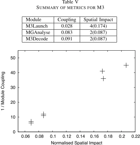
Tables IV-V summarise the results presented for 7Z and M3, with entries for coupling and spatial impact for each instrumented module. Note that normalised values are given in brackets. These values are ratios of the actual spatial impact value to the maximum possible spatial impact value). From Equation 1, a higher (resp. lower) module coupling value is indicative of a more loosely (resp. more tightly) coupled module.
A. Hypothesis Validation
In Section IV-C, we put forward a hypothesis regarding the relationship between module coupling and spatial impact. The hypothesis suggested that modules with tighter (resp. looser) coupling values will exhibit a higher (resp. lower) spatial impact.
Table III
SUMMARY OFFG FIEXPERIMENTS
Module 8-bit 32-bit 64-bit Total
FGInterface 12960 108864 559872 681696 FGPropulsion 77760 743904 155520 977184
FGLGear 46656 12096 399168 457920
137376 864864 1114560 2116800
Table IV
SUMMARY OF METRICS FOR7Z
Module Coupling Spatial Impact
LZMADecode 0.143 2(0.069)
7zCRC 0.167 2(0.069)
7zInput 0.024 5(0.172)
7zStream 0.022 6(0.207)
7zFileHandle 0.143 2(0.069)
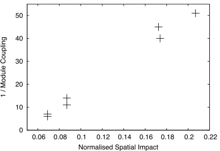
As mentioned, the 7Z and M3 target systems are used to verify the possible relationship between coupling and spatial impact. A graphical representation of the relationship can be seen in Figure 1 (where each ofα, β, γhas been set to 2, as in [17]). Spatial impact, in these graphs, has been normalised to account for variations in the size of target systems. This is performed by expressing the spatial impact of a module as a proportion of the maximum possible spatial impact, i.e., as a proportion of the maximum number of modules that could have been corrupted. In Figure 1, we plot the reciprocal of the coupling values against normalised spatial impact to counteract the rather unintuitive characteristic of the adopted coupling metric (see Equation 1 and discuss in Section IV). From Figure 1, we observe that there is a direct relationship between coupling and spatial impact, i.e., tighter coupling means higher spatial impact.
To support this assertion we calculate the Spearman’s rank correlation coefficient, which assesses how well the relationship between two variables can be described using a monotonic function. Here, the two variables are normalised spatial impact and the reciprocal of module coupling. Since there are repeated data, we use Equation 4, where xi, yi
are the ranks of the raw scores, and x,¯ y¯ are the rank averages [46].
ρ=
P
i(xi−¯x)(yi−y¯)
pP
i(xi−x¯)2Pi(yi−y¯)2
(4)
Table V
SUMMARY OF METRICS FORM3
Module Coupling Spatial Impact
M3Launch 0.028 4(0.174)
MGAnalyse 0.083 2(0.087)
M3Decode 0.091 2(0.087)
0 10 20 30 40 50
0.06 0.08 0.1 0.12 0.14 0.16 0.18 0.2 0.22
1 / Module Coupling
Normalised Spatial Impact
Figure 1. Plot of normalised spatial impact against DhamaCoupling(2,2,2)
are shown in Figures 1-4. We observe similar patterns across the plots in Figures 1-4. We conclude that, for the classes of software we considered, there is a correlation between coupling and spatial impact. Specifically, a more tightly coupled module will exhibit a higher spatial impact, thus providing evidence to support our hypothesis.
We acknowledge the fact that more target systems need to be used to fully confirm the relationship between coupling and spatial impact. However, the fact that two different target systems, from different application domains, do not violate the hypothesis, serves to strengthen the assertion.
B. Locating Detectors Based on Coupling
Based on the asserted correlation between module coupling and spatial impact, we now use module coupling as a guide when locating detectors, rather than using spatial impact. Due to the aforementioned correlation, module coupling can be used to highlight potentially vulnerable modules in a software system, i.e., modules that are likely to facilitate the propagation of errors to many other modules in a software system. The benefit of using module coupling in this way is that module coupling values can be obtained at an earlier stage of the software development lifecycle than spatial impact or any other metrics that have been previously proposed, including [4].
From Table VI, it is evident that modules FGInterface
andFGPropulsionhave much lower module coupling values than other modules (see Equation 1 for rationale), i.e., they display a higher level of coupling. Thus, we hypothesise that these modules are prime candidates for detector locations. To ascertain that these two modules are indeed viable locations,
0 10 20 30 40 50
0.06 0.08 0.1 0.12 0.14 0.16 0.18 0.2 0.22
1 / Module Coupling
Normalised Spatial Impact
Figure 2. Plot of normalised spatial impact against DhamaCoupling(4,2,2)
0 10 20 30 40 50
0.06 0.08 0.1 0.12 0.14 0.16 0.18 0.2 0.22
1 / Module Coupling
Normalised Spatial Impact
Figure 3. Plot of normalised spatial impact against DhamaCoupling(2,4,2)
we instrument the three FG modules and run fault injection experiments. If these two modules are effective locations then we would anticipate a significant reduction in the number of failures observed during fault injection analysis. To verify this, we conducted fault injection experiments. The results are summarised in Table VII. The column labeled
Originalshows the proportion of fault injection experiments that lead to a system failure. The Wrapped column shows the proportion of fault injection experiments that lead to a system failure, after the module has been wrapped with de-tectors. For the detector wrapper, we instrumented modules such that all variables were triplicated and a comparison test performed. The comparison test was used as the default detector. We observe that, by protecting FGInterface with a detector, the failure rate drops by a factor of 100, while protecting moduleFGPropulsionleads to a drop by a factor of 1000. On the other hand, wrappingFGLGear only leads to a drop in failure rate by a factor of 10. Hence, wrapping modulesFGInterfaceandFGPropulsionis indeed beneficial, as indicated by the module coupling metric.
[image:8.612.63.287.72.304.2] [image:8.612.321.547.257.413.2]0 10 20 30 40 50
0.06 0.08 0.1 0.12 0.14 0.16 0.18 0.2 0.22
1 / Module Coupling
Normalised Spatial Impact
Figure 4. Plot of normalised spatial impact against DhamaCoupling(2,2,4)
Table VI
SUMMARY OF METRICS FORFG
Module Coupling Spatial Impact FGInterface 0.023 32(0.151) FGPropulsion 0.042 21(0.099)
FGLGear 0.125 17(0.080)
Table VII
SYSTEM FAILURE RATES ASSOCIATED WITH ALL FAULT INJECTED EXECUTIONS OF INSTRUMENTED MODULES
Module Original Wrapped
Failure Rate Failure Rate
FGInterface 0.004582688 0.000045475 FGPropulsion 0.002481621 0.000002047 FGLGear 0.001471873 0.000135395
FGPropulsion, to show higher spatial impact values. This is confirmed by values shown in Table VI.
C. Discussion
We have performed a large number of fault injection experi-ments to (i) establish a correlation between module coupling and spatial impact and (ii) ascertain that modules, indicated as vulnerable by module coupling values, are indeed those that need to be protected by detectors. Figures 1- 4 show that there is a correlation between these two metrics, while Table VII shows that the failure rate of the system can be reduced significantly when the identified modules are protected with detectors. This approach has allowed us to use a metric, namely module coupling, as an early indicator of vulnerable modules in software systems.
We wish to point out that the relationship between cou-pling and dynamic dependability metrics has been investi-gated only for spatial impact. However, there are several other error propagation metrics, such as error permeability and coverage, that could be investigated. Our observations and conclusions do not extend to these dynamic metrics. We conjecture that results regarding a relationship between static metrics such as coupling and dynamic dependability
metrics such as coverage may be inconclusive, as reported in [32], due to the fact that coverage does not capture module interactions. Other dynamic metrics exist that propose to indicate the location of potential vulnerabilities in a software system. However, most of these can only be evaluated during the validation of a dependable software system, which occurs at a very late stage of the software development lifecycle. Further, the definition of several existing metrics do not coincide with those of module coupling, making it difficult to derive a correlation between module coupling and the other metrics. For example, error permeability, as proposed in [4], captures the likelihood of an error to propagate along a given path within a module, whereas module coupling captures the relationships between modules. On the other hand, the authors of [6] proposed two metrics; influence and separation. Influence captures the impact of a module m1
on modulem2, which contrasts with module coupling, that
attempts to capture the impact of one module on its module neighbourhood. On the other hand, separation captures how isolated a module is from other modules in a software sys-tem. Thus, separation can be viewed as the dual of module coupling. It can be speculated that separation is negatively correlated to module coupling, in that a higher (resp. lower) coupling implies a lower (resp. higher) separation. Given the work presented in this paper, this may represent an area for future investigation.
D. Limitations
There are some limitations to the approach described in this paper. Firstly, the correlation between module coupling and spatial impact has been asserted based on several modules in several applications from different application domains. To increase confidence in the existence of this correlation, it is important to evaluate it in the context of many more software systems from more applications domains. However, intuitively, when a module has a high coupling, it means that it interacts with many other modules in the system, potentially impacting on these when corrupted. Thus, there is a clear rationale underlying the hypothesised relationship. Another potential limitation is that the approach described in this paper operates at the level of modules, which is a higher level of abstraction than methodologies such as [4], where detector locations are identified at the level of signals and parameters. However, as outlined previously, these loca-tions can only be obtained during software system validation, whereas the approach described in this paper allows detector locations to be obtained far earlier.
[image:9.612.64.290.68.224.2]fact that, generally, a fault-intolerant software is developed and then subsequently enhanced with dependability mech-anisms [2] [3]. Thus, our approach fits well with current software engineering practice. Overall, in this context, our approach will allow a software engineers to conduct a cost-benefit analysis, whereby, after developing a software system, they will be able to evaluate the coupling of modules in the software system and decide where is best to locate dependability components.
VII. SUMMARY ANDFUTUREWORK
In this section, we provide a summary of the work under-taken and discuss areas for future research relating to the contributions of this paper.
A. Summary
Our main objective was to develop an approach that al-lows early identification of effective detector locations in dependable software design. Current metrics operate at a late stage of the software development lifecycle, making them potentially undesirable, as any problem may require expensive software redesign or reengineering. On the other hand, the early identification of detector locations allows software engineers to incorporate and investigate the effi-ciency of detectors much earlier in software development. Our approach is based on identifying a correlation between a static metric (module coupling) and a dynamic metric (spatial impact). In particular, we showed that a correlation exists between these two metrics, based on fault injection experiments conducted on two different software from dif-ferent application domains. Then, based on this correlation, we identified potential detector locations in another software system using module coupling values as a guide. Our results demonstrate that our approach is promising, as fault injection experiments performed on the indicated locations can lead to a 1000-fold reduction in system failures.
B. Future Work
In future work we plan to conduct more experiments on a variety of software systems, with the overarching intention of further evaluating the relationship identified in this paper in the context of different software systems and alternative definitions of module coupling. Further, we intend to con-duct similar experiments under alternative fault models in order to determine the extent to which the results presented in this paper extend to various classes of errors, e.g., errors induced by implementation defects and bugs.
REFERENCES
[1] J.-C. Laprie,Dependability: Basic Concepts and Terminology. Springer-Verlag, December 1992.
[2] A. Arora and S. S. Kulkarni, “Detectors and correctors: A theory of fault-tolerance components,” inProceedings of the 18th IEEE International Conference on Distributed Comput-ing Systems, May 1998, pp. 436–443.
[3] A. Jhumka, F. Freiling, C. Fetzer, and N. Suri, “An approach to synthesise safe systems,”International Journal of Security and Networks, vol. 1, no. 1, pp. 62–74, September 2006. [4] M. Hiller, A. Jhumka, and N. Suri, “Epic: profiling the
propagation and effect of data errors in software,” IEEE Transactions on Computers, vol. 53, no. 3, pp. 512–530, May 2004.
[5] A. Jhumka and M. Hiller, “Putting detectors in their place,” in Proceedings of the 3rd IEEE International Conference on Software Engineering and Formal Methods, September 2005, pp. 33–42.
[6] A. Jhumka, M. Hiller, and N. Suri, “Assessing inter-modular error propagation in distributed software,” inProceedings of the 20th IEEE International Symposium on Reliable Dis-tributed Systems, January 2001, pp. 152–161.
[7] W. Abdelmoez, D. E. M. Nassar, M. Shereshevsky, N. Gradet-sky, R. Gunnalan, H. H. Ammar, B. Yu, and A. Mili, “Error propagation in software architectures,” in Proceedings of the 10th IEEE International Software Metrics Symposium, September 2004, pp. 384–393.
[8] M. Leeke and A. Jhumka, “Towards understanding the impor-tance of variables in dependable software,” inProceedings of the 8th European Dependable Computing Conference, April 2010, pp. 85–94.
[9] ——, “An automated wrapper-based approach to the design of dependable software,” inProceedings of the 4th International Conference on Dependability, August 2011, pp. 43–50. [10] W. Stevens, G. Myers, and L. Constantine, “Structured
de-sign,”IBM Systems Journal, vol. 13, no. 2, pp. 115–139, June 1974.
[11] E. Yourdon and L. Constantine,Structured Design: Funda-mentals of a Discipline of Computer Program and Systems Design. Prentice-Hall, February 1979.
[12] M. Page-Jones, The Practical Guide to Structured Systems Design. New York: YOURDON Press, May 1980. [13] A. J. Offutt, M. J. Harrold, and P. Kolte, “A software
metric system for module coupling,”Journal of Systems and Software, vol. 20, no. 3, pp. 295–308, March 1993.
[14] R. Harrison, S. J. Counsell, and R. V. Nithi, “An evaluation of the mood set of object-oriented software metrics,” IEEE Transactions on Software Engineering, vol. 24, no. 6, pp. 491–496, June 1998.
[15] S. Kramer and H. Kaindl, “Coupling and cohesion metrics for knowledge-based systems using frames and rules,”ACM Transactions on Software Engineering and Methodology, vol. 13, no. 3, pp. 332–358, July 2004.
[18] S. Chidamber and C. F. Kemerer, “Towards a metrics suite for object-oriented design,” inProceedings of the ACM SIGPLAN International Conference on Object-Oriented Programming, Systems, Languages and Applications, June 1991, pp. 197– 211.
[19] ——, “A metric suite for object-oriented design,” IEEE Transactions on Software Engineering, vol. 20, no. 6, pp. 476–493, June 1994.
[20] J. M. Beiman and L. M. Ott, “Measuring functional cohe-sion,”IEEE Transactions on Software Engineering, vol. 20, no. 8, pp. 644–657, August 1994.
[21] L. M. Ott and J. M. Beiman, “Program slices as an abstraction for cohesion measurement,”Information and Software Tech-nology, vol. 40, no. 11-12, pp. 691–699, December 1998.
[22] T. M. Meyers and D. Binkley, “An empirical study of slice-based cohesion and coupling metrics,”ACM Transactions on Software Engineering and Methodology, vol. 17, no. 1, pp. 1–27, December 2007.
[23] L. C. Briand, J. W. Daly, and J. Wust, “A unified framework for coupling measurement in object-oriented software,”IEEE Transactions on Software Engineering, vol. 25, no. 1, pp. 91– 121, January 1999.
[24] E. Arisholm, L. C. Briand, and A. Føyen, “Dynamic coupling measurement for object-oriented software,” IEEE Transac-tions on Software Engineering, vol. 30, no. 8, pp. 491–506, August 2004.
[25] S. M. Yacoub, H. H. Ammar, and T. Robinson, “Dynamic metrics for object-oriented designs,” inProceedings of the 5th International Software Metrics Symposium, November 1999, pp. 50–61.
[26] N. Gupta and P. Rao, “Program execution based module cohesion measurement,” inProceedings of the 16th IEEE In-ternational Conference on Automated Software Engineering, September 2001, p. 144.
[27] V. R. Basili, L. C. Briand, and W. L. Melo, “A validation of object-oriented design metrics as quality indicators,”IEEE Transactions on Software Engineering, vol. 22, no. 10, pp. 751–761, October 1996.
[28] L. C. Briand, J. Wust, J. W. Daly, and D. V. Porter, “Exploring the relationship between design measures and software quality in object-oriented systems,”Journal of Systems and Software, vol. 51, no. 3, pp. 245–273, May 2000.
[29] G. Gui and P. D. Scott, “Ranking reusability of software components using coupling metrics,”Journal of Systems and Software, vol. 80, no. 9, pp. 1450–1459, September 2007.
[30] W. Li and A. Henry, “Object-oriented metrics that predict maintainability,” Journal of Systems and Software, vol. 23, no. 2, pp. 111–122, November 1993.
[31] F. G. Wilkie and B. A. Kitchenham, “An investigation of coupling, reuse and maintenance in a commercial c++ appli-cation,”Information and Software Technology, vol. 43, no. 13, pp. 801–812, November 2001.
[32] K. Goseva-Popstojanova, “The impact of dynamic metrics on identification of the failure prone parts of software,” NASA, Lane Derpatment of Computer Science and Electrical Engineering,West Virginia University, WV, Presentation, June 2006.
[33] D. Powell, E. Martins, J. Arlat, and Y. Crouzet, “Estimators for fault tolerance coverage evaluation,” IEEE Transactions on Computers, vol. 44, no. 2, pp. 261–274, June 1995.
[34] M. Hiller, A. Jhumka, and N. Suri, “An approach for analysing the propagation of data errors in software,” in
Proceedings of the 31st IEEE/IFIP International Conference on Dependable Systems and Networks, July 2001, pp. 161– 172.
[35] ——, “On the placement of software mechanisms for detec-tion of data errors,” in Proceedings of the 32nd IEEE/IFIP International Conference on Dependable Systems and Net-works, June 2002, pp. 135–144.
[36] V. Cortellessa and V. Grassi, “A modeling approach to analyze the impact of error propagation on reliability of component-based systems,” inProceedings of the 10th International Con-ference on Component-Based Software Engineering, Septem-ber 2007, pp. 140–156.
[37] V. G. A Filieri, C Ghezzi and R. Mirandola, “Reliability analysis of component-based systems with multiple failure modes,” inProceedings of the 13th International Symposium on Component-Based Software Engineering, June 2010, pp. 1–20.
[38] C. L. Blackmon and M.-L. Yin, “A design tool for large scale fault-tolerant software systems,” inProceedings of the Annual Reliability and Maintainability Symposium, January 2004, pp. 256–260.
[39] M. W. Lipton and S. S. Gokhale, “Heuristic component placement for maximizing software reliability,” in Recent Advances in Reliability and Quality in Design, H. Pham, Ed. Springer, June 2008, ch. 15, pp. 309–330.
[40] D. Powell, “Failure model assumptions and assumption cov-erage,” inProceedings of the 22nd International Symposium on Fault-Tolerant Computing, July 1992, pp. 386–395.
[41] R. S. Pressman, Software Engineering: A Practitioner’s Ap-proach (6th Edition). McGraw-Hill, April 2008.
[42] 7-Zip, “http://www.7-zip.org/,” September 2011.
[43] Mp3Gain, “http://mp3gain.sourceforge.net/,” September 2011.
[44] FlightGear, “http://www.flightgear.org/,” September 2011.
[45] M. Hiller, A. Jhumka, and N. Suri, “Propane: An environment for examining the propagation of errors in software,” in Pro-ceedings of the 11th ACM SIGSOFT International Symposium on Software Testing and Analysis, July 2002, pp. 81–85.