Interrelation between Dislocation Loops and an Edge Dislocation
Eiichi Kuramoto, Kazuhito Ohsawa and Tetsuo Tsutsumi
Research Institute for Applied Mechanics, Kyushu University, Kasuga 816-8580, Japan
Since it has recently become an important subject to study the interrelation between a dislocation loop and a straight edge dislocation because of dynamic behaviors of small dislocation loops under irradiation condition, the simulation studies were made in model Fe lattice. It was found that dislocation cores both for a loop and a dislocation can be expressed by the regular array of three types of crowdions and have stable positions of b/3 periodicity, but this regularity and periodicity are disturbed as the decrease of the loop size. The relation between a dislocation core and crowdion types are also studied. Furthermore, this change gives rise to the increase of the inherent lattice resistance (Peierls stress) for the dislocation loops.
(Received September 10, 2004; Accepted January 6, 2005)
Keywords: dislocation loop, core structure, crowdion, Peierls stress
1. Introduction
It is well-known that dislocation loops are produced in crystals through the condensation process of supersaturated point defects such as vacancies and self-interstitial atoms (SIAs) and also produced as punched-out loops from oversized precipitates in the matrix, furthermore it is recently known that they are produced through the direct formation (SIA loops) from cascades induced by the irradiation which produces high energy primary knock-on atoms (PKAs). In the last one it is recognized that emitted small SIA clusters (SIA loops) make one dimensional motion and disappear at sinks such as dislocations and grain boundaries, resulting in the void swelling due to the so-called production bias2–4)(an
important bias in the matrix under irradiation together with the dislocation bias1)). SIA loops which make one
dimen-sional motion are bundles of crowdions, that is, dislocation loops of the edge character with Burgers vectora=2h111iin bcc metals. Easy one dimensional motion of small SIA loops to sinks gives rise to excess vacancies in the matrix which cause void swelling of the material under irradiation. Consequently the detailed studies of the structure and the dynamic motion of small SIA clusters (loops) are required to have the comprehensive understanding for this void swelling phenomenon which plays a key role for the material development in the irradiation environments such as fission reactors and fusion reactors. In this paper the interrelation between dislocation loops and an edge dislocation will be investigated on the standpoint of both point defects (crow-dions) and a dislocation.
2. Calculations
In order to investigate fundamental characters of disloca-tion loops and a straight edge dislocadisloca-tion, model Fe lattice was constructed by using Finnis-Sinclair potential5)and into
a model lattice a straight edge dislocation or a bundle of crowdions ofa=2h111i Burgers vector was introduced. The size of the model lattice must be large enough to contain the defects with a long range strain field, such as a dislocation, and a size of simulation box is about 80 b (b: magnitude of Burgers vector) cubic was used for the static calculation, but
for the molecular dynamic calculation (MD calculation) usually smaller boxes were used. Relaxed structures were obtained by the static calculation or the MD calculation. The fixed boundary condition or the periodic boundary condition was applied depending on the defects in the model lattice, that is, the former for a bundle of crowdions and the latter for a straight edge dislocation along the dislocation line. The present positions of a dislocation line and a dislocation loop (variable along a loop periphery) were determined by a conventional way, that is, as a position where the
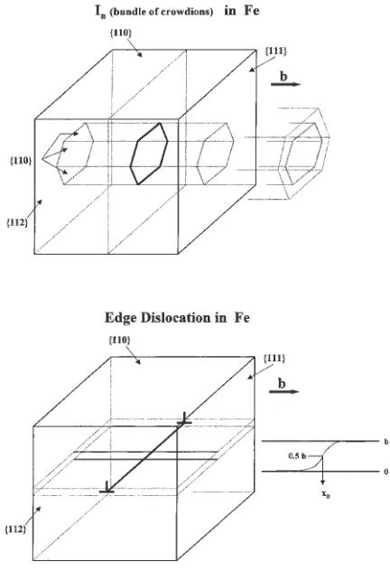
displace-Fig. 1 Fe model lattice which contains a dislocation loop of a hexagonal shape and a straight edge dislocation with the method to determine the center of a dislocation core where the displacement between two atomic planes just above and below a slip plane becomesb=2.
Special Issue on Fusion Blanket Structural Materials R&D in Japan
[image:1.595.318.534.425.741.2]ment between two atomic planes just above and below a slip plane becomes b=2 as shown in Fig. 1. Each crowdion constituting a loop, especially ones existing on a loop periphery was characterized as a deviation from the isolated crowdion, that is, the change of a distribution of the interatomic distance between adjacent two atoms along the crowdion axis. The core structures of an edge dislocation and a dislocation loop were also obtained by drawing the atomic configurations obtained after full relaxation of a whole
lattice. Dynamical properties were studied under the con-dition of the shear stress application, which was made by a conventional way for a straight edge dislocation, but for a dislocation loop was made axial symmetrically as shown in Fig. 2. Behaviors of small loops at finite temperatures were studied by using MD calculations.6–11)
3. Results and Discussion
3.1 Crowdions (isolated and bundled) and edge
disloca-tion
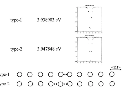
It is well known that a crowdion has a structure which has an extra atom on the crowdion axis and has a strain field extending along this axis,i.e.,h111i direction in the case of bcc metals. To characterize this crowdion the distribution of the interatomic distance between adjacent two atoms along a crowdion axis, that is, along h111i direction was obtained after full relaxation of a whole crystal which has a crowdion at a central position. Two kinds of distribution were obtained as shown in Fig. 3, where two patterns are shown, namely, one shortest distance exist (type 1), and two shortest distances exist (type 2) in the central position of a crowdion. In the other words, the center of the strain distribution is located between two atoms in the former, but that is located on an atom in the latter. These two have almost equal energies as shown in this figure, where a slightly higher energy is seen for the type 2 than the type 1.
These distributions for isolated crowdions are, however, changed when crowdions are bundled, that is, in dislocation Fig. 2 The method to apply the axially symmetrical shear stress on a
dislocation loop of a hexagonal shape.
Fig. 3 Two types of crowdions in Fe: type 1 and type 2 with their formation energies.
[image:2.595.55.282.68.256.2] [image:2.595.92.513.468.774.2]loops and in a straight edge dislocation. The most typical case is for a straight edge dislocation ofa=2h111iBurgers vector lying on a {110} plane extending alongh112idirection, and the distribution of the atomic distance for a crowdion existing
[image:3.595.87.510.80.408.2] [image:3.595.113.485.523.696.2]rather low. Type2þand2are slightly deformed structures to plus (one direction along h111icrowdion axis) or minus (the opposite) direction of the type 2 for an isolated crowdion and the strain localization is again low compared with that for the isolated one.
The reason why three types are needed comes from the crystal structure itself, that is, as shown in Fig. 4 (inserted figure),h112i direction of a straight edge dislocation has a periodic structure of three atomic distances on {110} plane. There exist three types of core structures corresponding to these three types of crowdions as shown in this figure, but schematically. The ones obtained from the real simulation are shown in Fig. 5, the cross sectional view of a straight edge dislocation line, where type 1 crowdion corresponds to the
dislocation core structure with its center on the boundary of two adjacent triangles, type2þcorresponds to that with its center in the downward triangle and type2corresponds to that with its center in the upward triangle.
The actual array of these three types of crowdions along a straight edge dislocation line is shown in Fig. 6, where periodic array of type 1,2þ,2expressed by dots are shown. The position of these dots representing crowdion types are placed at the positions of the dislocation core as shown in Figs. 4 and 5, almost on a straight line.
number of atoms along an edge dislocation line <112>
<111> {110} slip plane
Fig. 6 Edge dislocation lines expressed by dots corresponding to three types of crowdions placed at the positions of dislocation core center. Several adjacent stable positions of an edge dislocation lines are also shown in this figure.
Edge Dislocation Fe (a/2)<111> 1 1 1 2+ 2+ 2+ 2+ 2 2 2 1 1 2+ 2 22+ 1 2 1 2+ 2 1 1 1 2+ 2+ 2+ 2+ 2 2 2 1 1 2+ 2 22+ 1 2 1 2+ 1 1 1 2+ 2+ 2+ 2+ 2 2 2 1 12+ 2 22+ 1 2 1 2+ 2 1 1 1 2+ 2+ 2+ 2+ 2 2 2 1 1 2+ 2 22+ 1 2 1 2+ 2 2
b/3 b/3 b/3
Fig. 7 Schematic representation of a glide motion of a straight edge dislocation with changing the crowdion type just above the slip plane everyb=3periodicity which is already shown in Fig. 6.
{110} slip plane
<111>
<112>
number of atoms along 70 dislocation line
70
Dislocation
<111>
Fig. 8 70dislocation lines expressed by dots corresponding to three types
of crowdions placed at the positions of dislocation core center. Several adjacent stable positions of 70dislocation lines are also shown in this
figure.
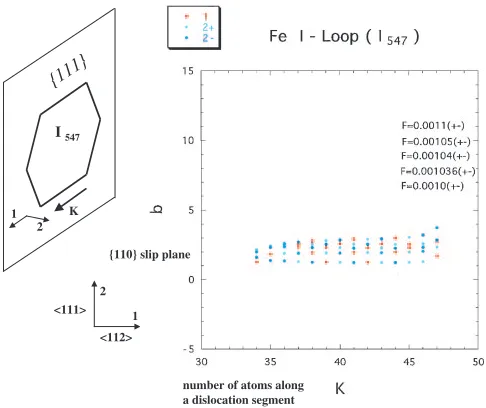
number of atoms along a dislocation segment {111}
K I 547
<111> <112> 1 1 2 2
{110} slip plane
Fig. 9 Segment of a dislocation loopI547expressed by dots corresponding
to three types of crowdions placed at the positions of dislocation core center. Several adjacent stbale positions of the segment of a loop are also shown in this figure.
[image:4.595.46.302.68.305.2] [image:4.595.285.542.75.310.2] [image:4.595.58.282.385.549.2] [image:4.595.305.548.386.590.2]3.2 Stable positions of edge dislocation and dislocation loops
In Fig. 6 not only as grown stable position of a straight edge dislocation, but also other stable positions obtained by stressing (shear stress) and unstressing processes are also shown, suggesting unexpected results that stable positions of a straight edge dislocation are distributed with a periodicity ofb=3and everyb=3periodicity crowdion types are regularly changed, that is, shifting one atomic distance along a dislocation line as shown schematically in Fig. 7, and every bperiodicity the same configuration of the crowdion type are realized. This is the peculiar property of a straight edge dislocation lying along h112i direction, but a dislocation along h111i direction, i.e., 70 dislocation has not this property, but has only one type of crowdions and a periodicity ofbas shown in Fig. 8.
It is then the most important subject that the situation observed here for a straight edge dislocation remains or not for dislocation loops. In order to investigate this point, the same analysis as that for a straight edge dislocation was made for dislocation loops of pure edge character which have a=2h111i Burgers vector and a hexagonal loop shape as shown in Fig. 1. The result for a segment of a hexagonal loop I547, a dislocation loop consisting of 547 SIAs (a bundle of crowdions), is shown in Fig. 9 (for a bottom segment of a hexagonal loop). The direction of the edge segment of this loop is almosth112i, just like a straight edge dislocation, but not exactly, especially at both end parts. The other stable positions obtained by the same way as that for a straight edge dislocation are similar to that for the edge case, but exactly speaking the b=3 periodicity is clearly disturbed by the segment end effect. This end effect is considered to be the very essential one for a dislocation loop. The schematic view of this hexagonal dislocation loop I547 with three types of crowdions is shown in Fig. 10.
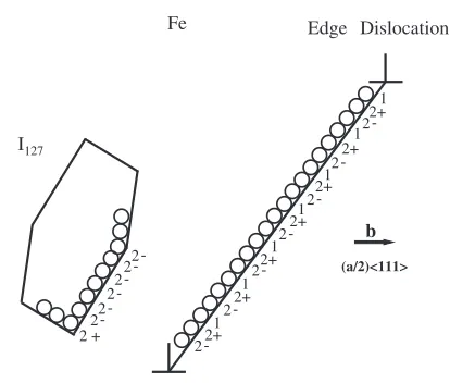
The same analysis was made for a segment of a hexagonal loopI127, a dislocation loop consisting of 127 SIAs (a bundle of crowdions) and the result is shown in Fig. 11, where the direction of the segment is noth112i, but is about 20 degree rotated toh111iand consists of only one type of crowdions, just like a 70dislocation mentioned above. The loop of this configuration has b periodicity as a 70 dislocation. The schematic view of this hexagonal dislocation loopI127with three types of crowdions is again shown in Fig. 12.
The change of the dislocation loop shape and the habit plane on which loops lie are obtained after full relaxation of a model lattice which has a loop and are shown in Figs. 13 and 14, where larger loops have {111} habit planes and each segment of a loop hash112idirection, but a habit plane for smaller loops has tendency to fall down to {110} plane, and the segment direction hash111idirection. These changes are considered to be responsible for the increase of lattice resistance of dislocation loops with decreasing loop size.
3.3 Peierls stress for edge dislocation and dislocation
loops
As the decrease of the size of a dislocation loop the regularity of an edge dislocation core structure is gradually disturbed, which results in the increase of the inherent lattice resistance (Peierls potential and Peierls force) for the
[image:5.595.318.528.72.252.2]2+ 2 1 1 1 2+ 2+ 2+ 2+ 2 2 2 2 1 1 1 2+ 2+ 2+ 2 2 22+ 1 2 1 2+ 2 1 2 2 2+ 1 2+ 1 I547 Edge Dislocation Fe b (a/2)<111>
Fig. 10 Schematic representation of a hexagonal dislocation loop with three types of crowdions which is already shown in Fig. 9.
number of atoms along a dislocation segment {110} slip plane
[image:5.595.308.548.313.512.2]<111> <112> 1 2 <111> {110} K I127 1 2 3 3 {111}
Fig. 11 Segment of a dislocation loopI127expressed by dots corresponding
to three types of crowdions placed at the positions of dislocation core center. 2 1 1 1 2+ 2+ 2+ 2+ 2 2 2 2 2 1 1 2 2+ 2 22+ 1 2 1 2+ 2 2 I127 Edge Dislocation Fe b (a/2)<111> 2 2 +
[image:5.595.319.526.585.761.2]dislocation loops as shown in Fig. 15 obtained from the stressing simulation shown in Fig. 2. It is considered that the regular structure of the periodicity ofb=3 in a straight edge dislocation gives the lowest Peierls stress, and the disturb-ance of this situation in dislocation loops results in the increase of Peierls stress.
3.4 Thermally activated motion of small dislocation
loops
In actual crystals small dislocation loops make one dimensional motion via thermally activated process. In this process the most important subject is if the kink pair formation occurs or not on a dislocation loop line. This has been studied by classical string model and the kink pair formation can be expected on a dislocation loop beyond a certain size, and the details of this study will be published on the other paper.12)MD simulations were also made for small
dislocation loopsI19,I37at 100 K, 300 K for 3 ps, and a clear kink pair formation has not been observed, but fluctuation of a dislocation loop line has been observed as shown in Fig. 16, where the result of MD simulation ofI37in Fe at 300 K, 3 ps is shown. The color change from blue to red shows the shift (2b) to the right direction in this figure. (Att¼0ps 10 eV is given to the central atom of the loop to the right direction) This simulation must be extended to larger dislocation loops which is the future work.
4. Summary
It is nowadays a very noticeable subject to study the interrelation between a dislocation loop and a straight edge dislocation, because in the field of radiation damage one dimensional motion of small interstitial clusters, dislocation loops is considered to be one of the origin of the bias effect which causes the void swelling of the materials used in the irradiation environments. Simulation studies were made in model Fe lattice to clarify the basic properties of dislocation loops on the viewpoint of the interrelation between a dislocation and a dislocation loop. It was found that dislocation cores both for a loop and a dislocation can be expressed by the regular array of three types of crowdions and have stable positions of b=3 periodicity, but this regularity and periodicity are disturbed as the decrease of the loop size. Furthermore, this change gives rise to the increase of the inherent lattice resistance (Peierls stress) for
{110}
{111}
1 1
1 1 1 1
1 1
1 - - <111> 2 - - <100> 3 - - <112> 4 - - <100> - <111> 4
4
1
1
1 1
1 1
2 2
3
3
3 3
3 3
1
1 1
1 2
2
1 1 1
1
4
1
1 1 1
1
1 3
3
<112> View
< 112 > < 111 >
(a) (b) (c) (d)
4
b
[image:6.595.50.286.70.239.2](a/2)<111>
Fig. 13 Types of dislocation loop shapes (a–d) in Fe obtained after
relaxation.
In(bundle of crowdions) in Fe
In I7 I19 I37 I61 I91 I127 I169 I217 I331 I547 I817
type c c b b b b d d d d d
[image:6.595.305.548.75.268.2]Fig. 14 Calculated size dependence of the type of the dislocation loops in Fe.
Fig. 15 Calculated Peierls stress as a fuction of the dislocation loop size for loops of hexagonal shape in Fe.
[image:6.595.47.289.299.410.2]Fe I37 300K 3psec
Fig. 16 Result of MD simulation ofI37in Fe at 300 K, 3 ps. Color change
from blue to red shows the shift (2b) to the right direction in this figure. (At t¼0ps 10 eV is given to the central atom of the loop to the right direction)
[image:6.595.69.267.459.656.2]the dislocation loops. Thermally activated motion of small loops has been studied by both classical string model and MD simulation, and kink pair formation on a dislocation loop has been discussed.
REFERENCES
1) R. Bullough, B. L. Eyre and K. Krishan: Proc. Roy. Soc. LondonA346 (1975) 81–102.
2) C. H. Woo and B. N. Singh: Philos. Mag.A65(1992) 889–912. 3) T. Diaz de la Rubia and M. W. Guinan: Phys. Rev. Lett.66(1991)
2766–2769.
4) N. Soneda and T. Diaz de la Rubia: Philos. Mag. A78(1998) 995–
1019.
5) M. W. Finnis and J. E. Sinclair: Philos. Mag. A 50(1984) 45–55, (erratum: Philos. Mag. A53(1986) 161).
6) E. Kuramoto: J. Nucl. Mat.276(2000) 143–153.
7) E. Kuramoto, K. Ohsawa and T. Tsutsumi: J. Nucl. Mat.283–287
(2000) 778–783.
8) E. Kuramoto: J. Comp.-Aided Mat. Design7(2000) 89–95.
9) E. Kuramoto, K. Ohsawa and T. Tsutsumi: Comp. Mod. Eng. Sci.,3
(2002) 193–200.
10) E. Kuramoto, K. Ohsawa and T. Tsutsumi: J. Nucl. Mater.307–311
(2002) 982–987.
11) E. Kuramoto, K. Ohsawa, J. Imai, K. Obata and T. Tsutsumi: Mater. Trans.45(2004) 34–39.